EP0341682A2 - Rippenplatte mit Stützbock - Google Patents
Rippenplatte mit Stützbock Download PDFInfo
- Publication number
- EP0341682A2 EP0341682A2 EP89108381A EP89108381A EP0341682A2 EP 0341682 A2 EP0341682 A2 EP 0341682A2 EP 89108381 A EP89108381 A EP 89108381A EP 89108381 A EP89108381 A EP 89108381A EP 0341682 A2 EP0341682 A2 EP 0341682A2
- Authority
- EP
- European Patent Office
- Prior art keywords
- plate
- base
- base plate
- fixing ribs
- ribbed
- Prior art date
- Legal status (The legal status is an assumption and is not a legal conclusion. Google has not performed a legal analysis and makes no representation as to the accuracy of the status listed.)
- Granted
Links
Images

Classifications
-
- E—FIXED CONSTRUCTIONS
- E01—CONSTRUCTION OF ROADS, RAILWAYS, OR BRIDGES
- E01B—PERMANENT WAY; PERMANENT-WAY TOOLS; MACHINES FOR MAKING RAILWAYS OF ALL KINDS
- E01B9/00—Fastening rails on sleepers, or the like
- E01B9/38—Indirect fastening of rails by using tie-plates or chairs; Fastening of rails on the tie-plates or in the chairs
- E01B9/44—Fastening the rail on the tie-plate
- E01B9/46—Fastening the rail on the tie-plate by clamps
- E01B9/48—Fastening the rail on the tie-plate by clamps by resilient steel clips
-
- E—FIXED CONSTRUCTIONS
- E01—CONSTRUCTION OF ROADS, RAILWAYS, OR BRIDGES
- E01B—PERMANENT WAY; PERMANENT-WAY TOOLS; MACHINES FOR MAKING RAILWAYS OF ALL KINDS
- E01B7/00—Switches; Crossings
- E01B7/20—Safety means for switches, e.g. switch point protectors, auxiliary or guiding rail members
Definitions
- the invention relates to a ribbed plate with a support frame according to the preamble of claim 1.
- Such ribbed plates are provided with wheel links and are used to guide the wheels of rail vehicles when temporarily, e.g. in the operation of a switch, the wheels are not guided by the rail.
- very strong lateral impact forces occur which have to be absorbed by the base and diverted to the base plate. This creates stress concentrations, particularly in the transition area from the base to the base plate, which lead to undesirable voltage peaks.
- a rib plate corresponding to the preamble of claim 1, which is known from DE-GM 81 10 904, is designed as a forged construction in which the rib plate and the base are forged in one piece.
- the generic ribbed plate is provided with fixing ribs that are milled out of the base plate. These milled fixing ribs are used to hold hook screws with which the rail is fixed on the rib plate.
- the generic ribbed plate is in need of improvement insofar as it is relatively complex to mill the fixing ribs out of the base plate, which leads to increased production costs.
- the risk of undesirable may not always be when milling out the fixing ribs from the base plate Notches can be excluded, which can lead to unduly high stress peaks in the foot area of the fixing ribs when appropriate loads occur.
- the fixing ribs of the generic ribbed plate are only suitable for the use of certain fastening elements for the rails, which include hook screws and hold-down springs.
- this fastening device for the rail is relatively expensive to install, so that the ribbed plate of the generic type also results in increased assembly costs for fastening the rails to the base plate.
- the entire ribbed plate can be formed as a part that can be produced essentially in one manufacturing process, the manufacturing costs of which are considerably lower than those of the ribbed plate of the generic type.
- Characterized in that the fixing ribs are integrally formed with the rib plate in one production step further improve the strength due to the avoidance of notch effects and the like, so that all types of possible loads can be absorbed in a favorable manner.
- the ribbed plate according to the invention has the particular advantage that particularly easy-to-mount rail fastening clips can be used to fix the rails, which only have to be inserted with one leg into the recess of the fixing ribs, after which the other leg of the rail fastening clip fixes the rail on the base plate .
- An example of a fastening clip which is basically suitable for use with the rib plate according to the innovation can be found in EP-A-206 618.
- the manufacture of the ribbed plate according to the invention offers itself as a one-piece forged part, since the best results in terms of low manufacturing costs and high strength can thereby be achieved.
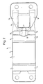
- a ribbed plate 1 is shown with a support bracket for the attachment of wheel links.
- the ribbed plate 1 has a base plate 2, the outline of which is essentially rectangular in accordance with FIG. 2.
- the bottom plate 2 has two fixing ribs 4, 5 on an upper side 3.
- the base plate 2 On the side opposite the top 3, the base plate 2 has a flat support surface 6.
- a base 7 is connected in one piece to the base plate 2, the base plate 2 and the base 7 representing an integral forged construction. As can be seen from Fig. 1, the base 7 extends substantially perpendicular to the base plate 2 and is provided with a recess 8 which serves to fasten the wheel control arm.
- the base 7 On the right side in FIG. 1, the base 7 has foot sections 9, 10, the design of which can be seen in detail from the top view in FIG. 2.
- the foot sections each serve to derive pressure loads in the area of the support surface 6, which rests on the sleepers.
- the fixing ribs 4, 5 are connected in one piece to the rib plate, the entire construction being forged.
- the fixing ribs 4, 5 each have a recess 11 and 12, respectively, which open towards the support surface 6. From Fig. 2 it can be seen that the fixing ribs 4, 5th Extend over the entire width of the base plate 2, the length of the recesses 11, 12 corresponding to the width of the base plate 2.
- the area of the fixing ribs 4, 5 which extends above the upper side 3 is semicircular, which is particularly favorable for manufacturing reasons.
- the ribbed plate 1 also has reinforcing ribs 13, 14, the design of which in the transition region between the base 7 and the base plate 2 is selected so that stress peaks can be avoided.
- Fig. 1 shows that a trough-shaped cavity 15 is formed on the underside of the base 7, which not only serves to save material, but also increases the elasticity of the ribbed plate 1.
- a central second cavity 16 is also provided between this cavity 15 and the adjacent fixing rib 5, which further improves the aforementioned effect.
- the ribbed plate 1 gives the particular advantage that in the recesses 11, 12 of Fixing ribs 4, 5, the legs of particularly easy-to-mount rail mounting brackets can be inserted, which considerably simplifies the mounting of a rail between the fixing legs 4, 5 on the base plate 2.
Landscapes
- Engineering & Computer Science (AREA)
- Mechanical Engineering (AREA)
- Architecture (AREA)
- Civil Engineering (AREA)
- Structural Engineering (AREA)
- Vehicle Interior And Exterior Ornaments, Soundproofing, And Insulation (AREA)
- Connection Of Plates (AREA)
- Dental Preparations (AREA)
- Containers Having Bodies Formed In One Piece (AREA)
- Table Devices Or Equipment (AREA)
- Polishing Bodies And Polishing Tools (AREA)
- Bathtub Accessories (AREA)
- Railway Tracks (AREA)
- Accommodation For Nursing Or Treatment Tables (AREA)
- Body Structure For Vehicles (AREA)
Abstract
Description
- Die Erfindung betrifft eine Rippenplatte mit Stützbock gemäß dem Oberbegriff des Anspruchs 1.
- Derartige Rippenplatten werden mit Radlenkern versehen und dienen zur Führung der Räder von Schienenfahrzeugen, wenn zeitweilig, z.B. im Betrieb einer Weiche, eine Führung der Räder durch die Schiene nicht gegeben ist. Hierbei treten unter Umständen sehr starke seitliche Stoßkräfte auf, die von dem Sockel aufgenommen und zur Bodenplatte abgeleitet werden müssen. Dabei entstehen besonders im Übergangsbereich von dem Sockel zur Bodenplatte Spannungskonzentrationen, die zu unerwünschten Spannungsspitzen führen.
- Aus diesem Grunde ist eine dem Oberbegriff des Anspruchs 1 entsprechende Rippenplatte, die aus dem DE-GM 81 10 904 bekannt ist, als Schmiedekonstruktion ausgeführt, bei der die Rippenplatte und der Sockel einstückig geschmiedet sind.
- Die gattungsgemäße Rippenplatte ist hierbei mit Festlegungsrippen versehen, die aus der Bodenplatte ausgefräst sind. Diese ausgefrästen Festlegungsrippen dienen zur Aufnahme von Hakenschrauben, mit denen die Schiene auf der Rippenplatte festgelegt wird.
- Die gattungsgemäße Rippenplatte ist insofern verbesserungsbedürftig, als das Ausfräsen der Festlegungsrippen aus der Bodenplatte relativ aufwendig ist, was zu erhöhten Fertigungskosten führt. Darüber hinaus kann beim Ausfräsen der Festlegungsrippen aus der Bodenplatte nicht immer die Gefahr unerwünschter Einkerbungen ausgeschlossen werden, die beim Auftreten von entsprechenden Belastungen zu ungebührlich hohen Spannungsspitzen im Fußbereich der Festlegungsrippen führen können.
- Des weiteren sind die Festlegungsrippen der gattungsgemäßen Rippenplatte nur für die Verwendung von bestimmten Befestigungselementen für die Schienen geeignet, die Hakenschrauben und Niederhaltefedern umfassen. Diese Befestigungseinrichtung für die Schiene ist jedoch relativ aufwendig anzubringen, so daß sich bei der gattungsgemäßen Rippenplatte auch erhöhte Montagekosten für die Befestigung der Schienen auf der Bodenplatte ergeben.
- Es ist daher Aufgabe der vorliegenden Erfindung, eine Rippenplatte der im Oberbegriff des Anspruchs 1 angegebenen Art zu schaffen, die kostengünstig herzustellen ist, eine insgesamt verbesserte Festigkeit aufweist und darüber hinaus die Anbringung von leicht zu montierenden Befestigungsklammern für die Schienen ermöglicht.
- Die Lösung dieser Aufgabe erfolgt durch die Merkmale des Anspruches 1.
- Dadurch wird zunächst erreicht, daß die gesamte Ripenplatte als ein im wesentlichen in einem Herstellungsvorgang herstellbares Teil ausgebildet werden kann, dessen Fertigungskosten erheblich unter denjenigen der gattungsgemäßen Rippenplatte liegen.
- Dadurch, daß die Festlegungsrippen in einem Fertigungsgang einstückig mit der Rippenplatte ausgebildet sind, ergibt sich ferner aufgrund der Vermeidung von Kerbwirkungen und dergleichen eine Verbesserung der Festigkeit, so daß alle Arten von möglichen Belastungen auf günstige Art und Weise aufgenommen werden können.
- Schließlich weist die erfindungsgemäße Rippenplatte den besonderen Vorteil auf, daß zur Festlegung der Schienen besonders leicht zu montierende Schienenbefestigungsklammern verwendet werden können, die mit einem Schenkel lediglich in die Ausnehmung der Festlegungsrippen eingeschoben werden müssen, wonach der andere Schenkel der Schienenbefestigungsklammer die Schiene auf der Bodenplatte festlegt. Ein Beispiel für eine Befstigungsklammer, die grundsätzlich zur Verwendung mit der neuerungsgemäßen Rippenplatte geeignet ist, kann der EP-A-206 618 entnommen werden.
- Die Unteransprüche haben vorteilhafte Weiterbildungen der Erfindung zum Inhalt.
- Danach bietet sich die Fertigung der erfindungsgemäßen Rippenplatte als einstückiges Schmiedeteil an, da sich hierdurch die besten Ergebnisse hinsichtlich niedriger Fertigungskosten und hoher Festigkeit erzielen lassen.
- Ein Ausführungsbeispiel der Erfindung ist in der Zeichnung dargestellt und wird im folgenden näher beschrieben.
- Es zeigt:
- Fig. 1 eine seitlich teilweise geschnittene Ansicht der Rippenplatte und
- Fig. 2 eine Draufsicht auf die Rippenplatte gemäß Fig. 1.
- In Fig. 1 ist eine Rippenplatte 1 mit Stützbock für die Befestigung von Radlenkern dargestellt.
- Die Rippenplatte 1 weist eine Bodenplatte 2 auf, deren Grundriß gemäß Fig. 2 im wesentlichen rechteckförmig ist. Die Bodenplatte 2 weist auf einer Oberseite 3 zwei Festlegungsrippen 4, 5 auf. Auf der der Oberseite 3 gegenüberliegenden Seite weist die Bodenplatte 2 eine plane Auflagefläche 6 auf.
- Einstückig mit der Bodenplatte 2 ist ein Sockel 7 verbunden, wobei die Bodenplatte 2 und der Sockel 7 eine einstückige Schmiedekonstruktion darstellen. Wie aus Fig. 1 ersichtlich ist, erstreckt sich der Sockel 7 im wesentlichen senkrecht zur Bodenplatte 2 und ist mit einer Ausnehmung 8 versehen, die zur Befestigung des Radlenkers dient.
- Auf der in Fig. 1 rechten Seite weist der Sockel 7 Fußabschnitte 9, 10 auf, deren Gestaltung im einzelnen aus der Draufsicht in Fig. 2 ersichtlich ist. Die Fußabschnitte dienen jeweils zur Ableitung von Druckbelastungen im Bereich der Auflagefläche 6, die auf den Schwellen aufliegt.
- Wie aus der Darstellung der Fig. 1 deutlich wird, sind die Festlegungsrippen 4, 5 einstückig mit der Rippenplatte verbunden, wobei die gesamte Konstruktion geschmiedet ist.
- Ferner wird aus Fig. 1 deutlich, daß die Festlegungsrippen 4, 5 jeweils eine Ausnehmung 11 bzw. 12 aufweisen, die sich zur Auflagefläche 6 hin öffnen. Aus Fig. 2 ist hierbei ersichtlich, daß sich die Festlegungsrippen 4, 5 über die gesamte Breite der Bodenplatte 2 erstrecken, wobei die Länge der Ausnehmungen 11, 12 der Breite der Bodenplatte 2 entspricht.
- Wie wiederum aus Fig. 1 ersichtlich ist, ist der sich oberhalb der Oberseite 3 erstreckende Bereich der Festlegungsrippen 4, 5 halbkreisförmig ausgebildet, was aus fertigungstechnischen Gründen besonders günstig ist.
- Die Rippenplatte 1 weist ferner Verstärkungsrippen 13, 14 auf, deren Ausbildung im Übergangsbereich zwischen dem Sockel 7 und der Bodenplatte 2 so gewählt ist, daß Spannungsspitzen vermieden werden können.
- Schließlich verdeutlicht Fig. 1, daß an der Unterseite des Sockels 7 ein wannenförmiger Hohlraum 15 ausgebildet ist, der nicht nur zur Materialersparnis dient, sondern ebenfalls die Elastizität der Rippenplatte 1 erhöht. Zwischen diesem Hohlraum 15 und der angrenzenden Festlegungsrippe 5 ist ferner ein mittiger zweiter Hohlraum 16 vorgesehen, der die zuvor genannte Wirkung weiter verbessert.
- Alles in allem ist mit der zuvor beschriebenen Ausführung der Rippenplatte 1 zum einen eine Verbesserung der Festigkeit im kritischen Bereich möglich, wobei die die Rippenplatte bildenden Elemente im wesentlichen die gleiche Wandstärke aufweisen, so daß der Gesenkschmiedevorgang erleichtert wird.
- Darüber hinaus ergibt die Rippenplatte 1 den besonderen Vorteil, daß in die Ausnehmungen 11, 12 der Festlegungsrippen 4, 5 die Schenkel von besonders einfach zu montierenden Schienenbefestigungsklammern eingeführt werden können, was die Montage einer Schiene zwischen den Festlegungsschenkeln 4, 5 auf der Bodenplatte 2 erheblich vereinfacht.
Claims (4)
mit einer Bodenplatte (2),
die auf ihrer Oberseite (3) Festlegungsrippen (4, 5) aufweist, und
die eine der Oberseite (3) gegenüberliegende Auflagefläche (6) aufweist; und
mit einem Sockel (7),
der sich im wesentlichen senkrecht zur Bodenplatte (2) erstreckt und
der mit der Bodenplatte (2) verbunden ist,
dadurch gekennzeichnet,
daß die Festlegungsrippen (4, 5) in einem Fertigungsgang einstückig mit der Bodenplatte (2) ausgebildet sind und
daß die Festlegungsrippen (4, 5) jeweils eine Ausnehmung (11, 12) aufweisen, die sich zur Auflagefläche (6) hin öffnet.
Priority Applications (1)
| Application Number | Priority Date | Filing Date | Title |
|---|---|---|---|
| AT89108381T ATE81366T1 (de) | 1988-05-13 | 1989-05-10 | Rippenplatte mit stuetzbock. |
Applications Claiming Priority (2)
| Application Number | Priority Date | Filing Date | Title |
|---|---|---|---|
| DE3816455A DE3816455A1 (de) | 1988-05-13 | 1988-05-13 | Rippenplatte mit stuetzbock |
| DE3816455 | 1988-05-13 |
Publications (3)
| Publication Number | Publication Date |
|---|---|
| EP0341682A2 true EP0341682A2 (de) | 1989-11-15 |
| EP0341682A3 EP0341682A3 (en) | 1990-08-16 |
| EP0341682B1 EP0341682B1 (de) | 1992-10-07 |
Family
ID=6354362
Family Applications (1)
| Application Number | Title | Priority Date | Filing Date |
|---|---|---|---|
| EP89108381A Expired - Lifetime EP0341682B1 (de) | 1988-05-13 | 1989-05-10 | Rippenplatte mit Stützbock |
Country Status (5)
| Country | Link |
|---|---|
| EP (1) | EP0341682B1 (de) |
| AT (1) | ATE81366T1 (de) |
| DE (2) | DE3816455A1 (de) |
| ES (1) | ES2035424T3 (de) |
| GR (1) | GR3005897T3 (de) |
Family Cites Families (11)
| Publication number | Priority date | Publication date | Assignee | Title |
|---|---|---|---|---|
| FR441465A (fr) * | 1911-03-18 | 1912-08-07 | Otto Krause | Platine pour rails |
| FR786072A (fr) * | 1934-04-14 | 1935-08-26 | Krupp Ag | Selle ou plaque d'assise de rail |
| DE642720C (de) * | 1935-07-26 | 1937-03-13 | Richard Zimmermann | Schienenbefestigung auf Rippenunterlegplatten |
| DE1126901B (de) * | 1956-08-03 | 1962-04-05 | Lockspike Ltd | Schienenbefestigung auf einer Unterlagsplatte oder Eisenbahnschwelle unter Verwendung eines federnden Befestigungsmittels |
| FR1315898A (fr) * | 1961-12-14 | 1963-01-25 | Fond Cromback | Coussinet de glissement pour aiguillage |
| US3338521A (en) * | 1967-03-17 | 1967-08-29 | Lockspike Ltd | Railway rail and fastening assembly |
| DE8110904U1 (de) * | 1981-04-10 | 1981-09-17 | Carl Dan. Peddinghaus Gmbh & Co Kg, 5828 Ennepetal | Rippenplatte |
| DE3245701C2 (de) * | 1982-12-10 | 1986-05-22 | Hoesch Ag, 4600 Dortmund | Rippenplatte |
| FR2580685B1 (fr) * | 1985-04-17 | 1987-11-27 | Cogifer Cie Gle Inst Ferroviai | Dispositif de support et de fixation d'un rail de chemin de fer |
| GB8515471D0 (en) * | 1985-06-19 | 1985-07-24 | Pandrol Ltd | Holding railway down on support member |
| DE8615192U1 (de) * | 1986-06-05 | 1986-08-07 | Thyssen Industrie AG Schmiedetechnik/Bergbautechnik, 5630 Remscheid | Weichenrippenplatte |
-
1988
- 1988-05-13 DE DE3816455A patent/DE3816455A1/de not_active Ceased
-
1989
- 1989-05-10 AT AT89108381T patent/ATE81366T1/de not_active IP Right Cessation
- 1989-05-10 EP EP89108381A patent/EP0341682B1/de not_active Expired - Lifetime
- 1989-05-10 DE DE8989108381T patent/DE58902400D1/de not_active Expired - Lifetime
- 1989-05-10 ES ES198989108381T patent/ES2035424T3/es not_active Expired - Lifetime
-
1992
- 1992-10-08 GR GR920401383T patent/GR3005897T3/el unknown
Also Published As
| Publication number | Publication date |
|---|---|
| DE3816455A1 (de) | 1989-11-23 |
| ES2035424T3 (es) | 1993-04-16 |
| EP0341682A3 (en) | 1990-08-16 |
| GR3005897T3 (de) | 1993-06-07 |
| EP0341682B1 (de) | 1992-10-07 |
| ATE81366T1 (de) | 1992-10-15 |
| DE58902400D1 (de) | 1992-11-12 |
Similar Documents
| Publication | Publication Date | Title |
|---|---|---|
| EP0420882B2 (de) | Schiene für schienenfahrzeuge | |
| WO2011032932A1 (de) | System zum befestigen einer schiene und befestigung einer schiene | |
| EP0304539A1 (de) | Schaltbrücke für elektrische Schaltgeräte, insbesondere Schütze | |
| EP0502331B1 (de) | Blattfederpaket | |
| DE3426949C2 (de) | ||
| EP0343149B1 (de) | Vorrichtung zum Befestigen von Backenschienen in Weichen | |
| DE3540895A1 (de) | Einrichtung zur anbringung einer baugruppe aus mechanisch miteinander verbundenen elektrischen geraeten an einer halterungsschiene | |
| DE2437172A1 (de) | Verstelleinrichtung fuer sitze | |
| DE69526211T2 (de) | Hupenschalter für lenkräder und polstermontageanordnung dafür | |
| EP0000711B1 (de) | Schütz mit frei zugänglichen, in unterschiedlichen Ebenen angeordneten Leitungsanschlüssen | |
| DE3230612A1 (de) | Vorrichtung zum befestigen von backenschienen oder fahrschienen in weichen | |
| EP0341682A2 (de) | Rippenplatte mit Stützbock | |
| DE10048787B4 (de) | Lagerung für einen Gleisabschnitt | |
| DE3225855A1 (de) | Schutzleiter-reihenklemme | |
| EP0700240B1 (de) | Elektrisches oder elektronisches Gerät für ein Kraftfahrzeug | |
| DE2706277A1 (de) | Siebboden | |
| DE3903297A1 (de) | Befestigungsanordnung, befestigungsklammer und distanzplatte fuer eisenbahnschienen | |
| DE2151903C3 (de) | Kontaktvorrichtung für elektrische Schaltgeräte oder Trennvorrichtungen | |
| DE19909283A1 (de) | Verfahren zur Befestigung von Sitzschienen | |
| EP0194538A2 (de) | Lattenrost für Betten | |
| DE9114712U1 (de) | Drucktastenfeld aus Kunststoff, insbesondere für Kommunikationsendgeräte | |
| DE10315503B3 (de) | Installationsgerät für Sammelschienen | |
| DE2462299C3 (de) | Klappanker-Relais | |
| DE10236792A1 (de) | Fliesenschneider | |
| DE4413029A1 (de) | Schutzleiteranschluß zum Anschließen an eine hutförmige Tragschiene |
Legal Events
| Date | Code | Title | Description |
|---|---|---|---|
| PUAI | Public reference made under article 153(3) epc to a published international application that has entered the european phase |
Free format text: ORIGINAL CODE: 0009012 |
|
| AK | Designated contracting states |
Kind code of ref document: A2 Designated state(s): AT BE CH DE ES FR GB GR IT LI LU NL SE |
|
| 17P | Request for examination filed |
Effective date: 19900322 |
|
| PUAL | Search report despatched |
Free format text: ORIGINAL CODE: 0009013 |
|
| AK | Designated contracting states |
Kind code of ref document: A3 Designated state(s): AT BE CH DE ES FR GB GR IT LI LU NL SE |
|
| 17Q | First examination report despatched |
Effective date: 19910819 |
|
| GRAA | (expected) grant |
Free format text: ORIGINAL CODE: 0009210 |
|
| AK | Designated contracting states |
Kind code of ref document: B1 Designated state(s): AT BE CH DE ES FR GB GR IT LI LU NL SE |
|
| REF | Corresponds to: |
Ref document number: 81366 Country of ref document: AT Date of ref document: 19921015 Kind code of ref document: T |
|
| GBT | Gb: translation of ep patent filed (gb section 77(6)(a)/1977) | ||
| REF | Corresponds to: |
Ref document number: 58902400 Country of ref document: DE Date of ref document: 19921112 |
|
| ET | Fr: translation filed | ||
| ITF | It: translation for a ep patent filed | ||
| REG | Reference to a national code |
Ref country code: GR Ref legal event code: FG4A Free format text: 3005897 |
|
| PGFP | Annual fee paid to national office [announced via postgrant information from national office to epo] |
Ref country code: SE Payment date: 19930415 Year of fee payment: 5 Ref country code: LU Payment date: 19930415 Year of fee payment: 5 |
|
| REG | Reference to a national code |
Ref country code: ES Ref legal event code: FG2A Ref document number: 2035424 Country of ref document: ES Kind code of ref document: T3 |
|
| PGFP | Annual fee paid to national office [announced via postgrant information from national office to epo] |
Ref country code: CH Payment date: 19930422 Year of fee payment: 5 |
|
| PGFP | Annual fee paid to national office [announced via postgrant information from national office to epo] |
Ref country code: GR Payment date: 19930430 Year of fee payment: 5 |
|
| PGFP | Annual fee paid to national office [announced via postgrant information from national office to epo] |
Ref country code: GB Payment date: 19930505 Year of fee payment: 5 |
|
| PGFP | Annual fee paid to national office [announced via postgrant information from national office to epo] |
Ref country code: BE Payment date: 19930512 Year of fee payment: 5 |
|
| PGFP | Annual fee paid to national office [announced via postgrant information from national office to epo] |
Ref country code: FR Payment date: 19930526 Year of fee payment: 5 |
|
| PGFP | Annual fee paid to national office [announced via postgrant information from national office to epo] |
Ref country code: AT Payment date: 19930527 Year of fee payment: 5 |
|
| PGFP | Annual fee paid to national office [announced via postgrant information from national office to epo] |
Ref country code: ES Payment date: 19930528 Year of fee payment: 5 |
|
| PGFP | Annual fee paid to national office [announced via postgrant information from national office to epo] |
Ref country code: NL Payment date: 19930531 Year of fee payment: 5 |
|
| PGFP | Annual fee paid to national office [announced via postgrant information from national office to epo] |
Ref country code: DE Payment date: 19930630 Year of fee payment: 5 |
|
| PLBE | No opposition filed within time limit |
Free format text: ORIGINAL CODE: 0009261 |
|
| STAA | Information on the status of an ep patent application or granted ep patent |
Free format text: STATUS: NO OPPOSITION FILED WITHIN TIME LIMIT |
|
| EPTA | Lu: last paid annual fee | ||
| 26N | No opposition filed | ||
| PG25 | Lapsed in a contracting state [announced via postgrant information from national office to epo] |
Ref country code: LU Free format text: LAPSE BECAUSE OF NON-PAYMENT OF DUE FEES Effective date: 19940510 Ref country code: GB Effective date: 19940510 Ref country code: AT Effective date: 19940510 |
|
| PG25 | Lapsed in a contracting state [announced via postgrant information from national office to epo] |
Ref country code: SE Effective date: 19940511 Ref country code: ES Free format text: LAPSE BECAUSE OF NON-PAYMENT OF DUE FEES Effective date: 19940511 |
|
| PG25 | Lapsed in a contracting state [announced via postgrant information from national office to epo] |
Ref country code: LI Effective date: 19940531 Ref country code: CH Effective date: 19940531 Ref country code: BE Effective date: 19940531 |
|
| BERE | Be: lapsed |
Owner name: CARL DAN. PEDDINGHAUS G.M.B.H. & CO. K.G. Effective date: 19940531 |
|
| PG25 | Lapsed in a contracting state [announced via postgrant information from national office to epo] |
Ref country code: GR Free format text: THE PATENT HAS BEEN ANNULLED BY A DECISION OF A NATIONAL AUTHORITY Effective date: 19941130 |
|
| PG25 | Lapsed in a contracting state [announced via postgrant information from national office to epo] |
Ref country code: NL Effective date: 19941201 |
|
| GBPC | Gb: european patent ceased through non-payment of renewal fee |
Effective date: 19940510 |
|
| NLV4 | Nl: lapsed or anulled due to non-payment of the annual fee | ||
| EUG | Se: european patent has lapsed |
Ref document number: 89108381.8 Effective date: 19941210 |
|
| PG25 | Lapsed in a contracting state [announced via postgrant information from national office to epo] |
Ref country code: FR Effective date: 19950131 |
|
| REG | Reference to a national code |
Ref country code: CH Ref legal event code: PL |
|
| PG25 | Lapsed in a contracting state [announced via postgrant information from national office to epo] |
Ref country code: DE Effective date: 19950201 |
|
| EUG | Se: european patent has lapsed |
Ref document number: 89108381.8 |
|
| REG | Reference to a national code |
Ref country code: FR Ref legal event code: ST |
|
| REG | Reference to a national code |
Ref country code: GR Ref legal event code: MM2A Free format text: 3005897 |
|
| REG | Reference to a national code |
Ref country code: ES Ref legal event code: FD2A Effective date: 20000403 |
|
| PG25 | Lapsed in a contracting state [announced via postgrant information from national office to epo] |
Ref country code: IT Free format text: LAPSE BECAUSE OF NON-PAYMENT OF DUE FEES;WARNING: LAPSES OF ITALIAN PATENTS WITH EFFECTIVE DATE BEFORE 2007 MAY HAVE OCCURRED AT ANY TIME BEFORE 2007. THE CORRECT EFFECTIVE DATE MAY BE DIFFERENT FROM THE ONE RECORDED. Effective date: 20050510 |