EP0337927A2 - Commutateur de gamme, en particulier pour un relais temporisé - Google Patents
Commutateur de gamme, en particulier pour un relais temporisé Download PDFInfo
- Publication number
- EP0337927A2 EP0337927A2 EP89730080A EP89730080A EP0337927A2 EP 0337927 A2 EP0337927 A2 EP 0337927A2 EP 89730080 A EP89730080 A EP 89730080A EP 89730080 A EP89730080 A EP 89730080A EP 0337927 A2 EP0337927 A2 EP 0337927A2
- Authority
- EP
- European Patent Office
- Prior art keywords
- locking
- locking pin
- range switch
- switch according
- sleeve
- Prior art date
- Legal status (The legal status is an assumption and is not a legal conclusion. Google has not performed a legal analysis and makes no representation as to the accuracy of the status listed.)
- Granted
Links
Images
Classifications
-
- H—ELECTRICITY
- H01—ELECTRIC ELEMENTS
- H01H—ELECTRIC SWITCHES; RELAYS; SELECTORS; EMERGENCY PROTECTIVE DEVICES
- H01H19/00—Switches operated by an operating part which is rotatable about a longitudinal axis thereof and which is acted upon directly by a solid body external to the switch, e.g. by a hand
- H01H19/02—Details
- H01H19/10—Movable parts; Contacts mounted thereon
- H01H19/11—Movable parts; Contacts mounted thereon with indexing means
- H01H19/115—Movable parts; Contacts mounted thereon with indexing means using molded elastic parts only
-
- G—PHYSICS
- G04—HOROLOGY
- G04G—ELECTRONIC TIME-PIECES
- G04G15/00—Time-pieces comprising means to be operated at preselected times or after preselected time intervals
-
- H—ELECTRICITY
- H01—ELECTRIC ELEMENTS
- H01C—RESISTORS
- H01C10/00—Adjustable resistors
- H01C10/14—Adjustable resistors adjustable by auxiliary driving means
Definitions
- the invention relates to a range switch, in particular for an electronic time relay according to the preamble of the main claim.
- range switches are provided in the cover of the housing of the time relay, with which, for example, different time ranges and different functional ranges can be set. These range switches have an adjustment element that can be actuated from the outside and is part of a switch. The switch specifies a desired number of switch positions that provide different time ranges and functions.
- Such a switch is relatively expensive in the miniaturization required for the current state of the art, so that the production costs of a timing relay are also higher.
- the invention has for its object to provide a range switch, especially for electronic timing relays according to the preamble of the main claim, which has a simple structure and is quick to assemble and is cheaper than a range switch according to the prior art.
- the adjusting element is designed as a continuous locking pin, which is directly in positive engagement with a switching element, and that a sleeve with locking recesses provided in its inner circumferential surface is placed in the cover, which in cooperation with the locking pin specifies locking positions for the switching element,
- the switch that must be used in the prior art can be omitted, whereby the structure can be downsized, the assembly can be simplified, and manufacturing costs can be reduced.
- the switching element is a potentiometer means that a very inexpensive switching element is used, which is manufactured in large numbers, and digital voltage values can also be made available for further processing, predetermined by the latching positions.
- a good deformability of the sleeve is ensured in that the locking pin has a diameter over part of its length in front of the locking area, which is smaller than the inner diameter of the sleeve.
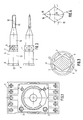
- the cover 1 of a housing for an electronic time relay shown in FIG. 1 is known per se and therefore need not be described in more detail.
- 1 bushes or sleeves 2, 3 are formed in the interior of the cover and are used to hold locking pins 4 shown in more detail in FIG. 2.
- incisions or depressions 5 are provided in the inner peripheral surface of the sleeve 2, 3, each of which describes a partial circle in cross section. Eight of these depressions 5 are predefined in the scope, whereby eight locking positions are defined.
- a further recess 6 is arranged, which, as will be described later, serves as an assembly aid for the pin 4 or for adjusting the position of a switching element which is in positive engagement with the locking pin.
- This recess 6 extends over the entire length of the sleeve 2, 3, while the locking recesses 5 are only in the interior of the relay facing end portion of the sleeve 2,3.
- the locking recesses 5 thus end at a shoulder or an undercut 7.
- the locking pin 4 is formed in one piece and has several functions and serves as an externally actuatable adjusting element, as a latching element and as a transmission element for the adjusting movement carried out from the outside onto a switching element.
- the switching element is a potentiometer which is located on a printed circuit board and is arranged in such a way that its actuating device, in the present exemplary embodiment this is a recess or recess, lies opposite the sleeve 2 or 3.
- the locking pin 4 has an adjustment area 8, a locking area 9 and an engagement area 10.
- the adjustment area 8 consists of a flange 11 in which a slot 12 is arranged for receiving the cutting edge of a screwdriver.
- the flange 11 is adjoined by a pin-shaped region 13 which has a diameter approximately corresponding to the inner diameter of the sleeve 2, 3. Between the pin-shaped area 13 and the locking area 9, the pin 4 is provided with a section 21 of reduced diameter to improve the deformability of the sleeve 2, 3, which merges into the locking area 9, this locking area 9 being shown in more detail in FIG. 4.
- a further pin-shaped extension area 14 is molded onto the latching area 9 and merges into the engagement area 10 designed as a cutting edge 15.
- This cutting edge 15 engages in the potentiometer, not shown, and the resistance of the potentiometer can thus be changed via the pin 4, 4 fixed digital resistance values being specified via the locking positions of the locking pin, by means of which different fixed voltage values can be derived.
- the locking area 9 of the locking pin is shown, which has a locking projection 16.
- the pin 4 has a rhombus-shaped cross section in the latching area 9, the corner forming the latching projection 16 as well as the corner opposite the latching projection 16, which forms the support area 17, being rounded.
- the radius of the locking projection 16 is smaller than that of the support region 17 and is adapted to the radius of the part-circular recesses 5 of the sleeve 2, 3.
- the dimensions of the locking area 9 are chosen such that the length between the center of the locking pin and the outer circumference of the locking projection 16 is greater than the length 18 between the center of the locking pin 4 to the outer peripheral surface of the support area 17.
- This length 18 corresponds to the inner radius of the through bore of the sleeve 2.3.
- the diameter of the section 21 which lies in front of the latching area corresponds, for example, to the length between the two pointed corners of the rhombus-shaped cross section.
- the angle 19 on the locking projection 16 is preferably 36 ° and the angle 20 30 °. This information is for the described Embodiment selected, of course, other shapes of the locking area 9 of the locking pin 4 are possible.
- the pin 4 When assembling the range switch, the pin 4 is inserted with its locking projection 16 into the continuous recess 6. In this position, the cutting edge 15 of the locking pin engages in a corresponding recess in the potentiometer, this position forming the zero position of the potentiometer. After inserting the locking pin, it can be rotated via the slot 12, the sleeve 2, 3 being elastically deformed due to the elasticity of its material - the sleeve 2, 3 is made of plastic - and the section 21 of reduced diameter whenever the locking projection 16 is located between the locking positions predetermined by the recesses 5. In this state, the length of the locking pin 4 between the locking projection 16 and the support area 17 is greater than the diameter of the sleeve 2, 3.
- the cover 1 On the top of the cover 1 there are markings around the sleeves 2, 3 which correspond, for example, to the different time ranges or different functions corresponding to the latching positions.
- a corresponding marking is provided on the surface of the flange 11 of the locking pin 4, wherein this marking can be formed by a recess in the flange 11.
- a stop can be provided, which can be produced, for example, in the pin-shaped area 13 by constriction with the formation of a nose. The nose then engages a protrusion located on the inner periphery of the sleeve.
- the switching element is a potentiometer.
- contact areas printed on a printed circuit board can be provided, for example, which can be bridged using a wiper.
- the grinder is, for example, via an axis connected to it, which can be inserted into the circuit board, in a fixed association with the contact surfaces, the other end of the axis is in a positive connection with the locking pin.
- the locking pin 4 is provided with a cutting edge 15 as an engagement element 10.
- it can also have a recess in its end, into which a corresponding engagement element on the switching element, i.e. engages on the potentiometer or on the grinder.
Applications Claiming Priority (3)
| Application Number | Priority Date | Filing Date | Title |
|---|---|---|---|
| DE3813115A DE3813115A1 (de) | 1988-04-15 | 1988-04-15 | Bereichsumschalter, insbesondere fuer ein elektronisches zeitrelais |
| DE3813115 | 1988-04-15 | ||
| DE8805203U DE8805203U1 (fr) | 1988-04-15 | 1988-04-15 |
Publications (3)
| Publication Number | Publication Date |
|---|---|
| EP0337927A2 true EP0337927A2 (fr) | 1989-10-18 |
| EP0337927A3 EP0337927A3 (en) | 1990-12-19 |
| EP0337927B1 EP0337927B1 (fr) | 1995-03-08 |
Family
ID=25867175
Family Applications (1)
| Application Number | Title | Priority Date | Filing Date |
|---|---|---|---|
| EP89730080A Expired - Lifetime EP0337927B1 (fr) | 1988-04-15 | 1989-03-22 | Commutateur de gamme, en particulier pour un relais temporisé |
Country Status (5)
| Country | Link |
|---|---|
| EP (1) | EP0337927B1 (fr) |
| AT (1) | ATE119710T1 (fr) |
| DE (3) | DE3813115A1 (fr) |
| ES (1) | ES2070189T3 (fr) |
| PT (1) | PT90275B (fr) |
Cited By (3)
| Publication number | Priority date | Publication date | Assignee | Title |
|---|---|---|---|---|
| EP0793161A1 (fr) * | 1996-02-27 | 1997-09-03 | Eaton Corporation | Bouton de réglage comprenant un dispositif de positionnement discret |
| EP0834892A2 (fr) * | 1996-10-02 | 1998-04-08 | AEG Hausgeräte GmbH | Dispositif d'indexation et commutateur rotatif pour appareil électroménager avec ce dispositif d'indexation |
| DE19919950A1 (de) * | 1999-04-30 | 2000-11-02 | Bsh Bosch Siemens Hausgeraete | Vorrichtung mit einer Drehachse, die in Drehrichtung zumindest zwei stabile Stellungen und zumindest einen instabilen Bereich aufweist |
Families Citing this family (1)
| Publication number | Priority date | Publication date | Assignee | Title |
|---|---|---|---|---|
| DE3813115A1 (de) * | 1988-04-15 | 1989-10-26 | Schleicher Relais | Bereichsumschalter, insbesondere fuer ein elektronisches zeitrelais |
Citations (4)
| Publication number | Priority date | Publication date | Assignee | Title |
|---|---|---|---|---|
| US4082925A (en) * | 1976-03-31 | 1978-04-04 | Cts Corporation | Rotary switch |
| FR2437078A1 (fr) * | 1978-09-21 | 1980-04-18 | Illinois Tool Works | Element de contact electrique tournant |
| GB2130796A (en) * | 1982-11-18 | 1984-06-06 | Alps Electric Co Ltd | Band selector switches |
| DE8805203U1 (fr) * | 1988-04-15 | 1988-07-14 | Schleicher Gmbh & Co Relais-Werke Kg, 1000 Berlin, De |
Family Cites Families (3)
| Publication number | Priority date | Publication date | Assignee | Title |
|---|---|---|---|---|
| US3264422A (en) * | 1961-12-26 | 1966-08-02 | Ford Motor Co | Turn signal connecting mechanism accumulator having pin and slide connection |
| US4110722A (en) * | 1977-07-18 | 1978-08-29 | Cts Corporation | Variable resistance control |
| DE3425752C2 (de) * | 1984-07-12 | 1986-05-15 | Endress U. Hauser Gmbh U. Co, 7867 Maulburg | Abgedichtete Potentiometer-Baugruppe |
-
1988
- 1988-04-15 DE DE3813115A patent/DE3813115A1/de active Granted
- 1988-04-15 DE DE8805203U patent/DE8805203U1/de not_active Expired
-
1989
- 1989-03-22 AT AT89730080T patent/ATE119710T1/de not_active IP Right Cessation
- 1989-03-22 EP EP89730080A patent/EP0337927B1/fr not_active Expired - Lifetime
- 1989-03-22 ES ES89730080T patent/ES2070189T3/es not_active Expired - Lifetime
- 1989-03-22 DE DE58909076T patent/DE58909076D1/de not_active Expired - Fee Related
- 1989-04-14 PT PT90275A patent/PT90275B/pt not_active IP Right Cessation
Patent Citations (4)
| Publication number | Priority date | Publication date | Assignee | Title |
|---|---|---|---|---|
| US4082925A (en) * | 1976-03-31 | 1978-04-04 | Cts Corporation | Rotary switch |
| FR2437078A1 (fr) * | 1978-09-21 | 1980-04-18 | Illinois Tool Works | Element de contact electrique tournant |
| GB2130796A (en) * | 1982-11-18 | 1984-06-06 | Alps Electric Co Ltd | Band selector switches |
| DE8805203U1 (fr) * | 1988-04-15 | 1988-07-14 | Schleicher Gmbh & Co Relais-Werke Kg, 1000 Berlin, De |
Cited By (4)
| Publication number | Priority date | Publication date | Assignee | Title |
|---|---|---|---|---|
| EP0793161A1 (fr) * | 1996-02-27 | 1997-09-03 | Eaton Corporation | Bouton de réglage comprenant un dispositif de positionnement discret |
| EP0834892A2 (fr) * | 1996-10-02 | 1998-04-08 | AEG Hausgeräte GmbH | Dispositif d'indexation et commutateur rotatif pour appareil électroménager avec ce dispositif d'indexation |
| EP0834892A3 (fr) * | 1996-10-02 | 1999-04-07 | AEG Hausgeräte GmbH | Dispositif d'indexation et commutateur rotatif pour appareil électroménager avec ce dispositif d'indexation |
| DE19919950A1 (de) * | 1999-04-30 | 2000-11-02 | Bsh Bosch Siemens Hausgeraete | Vorrichtung mit einer Drehachse, die in Drehrichtung zumindest zwei stabile Stellungen und zumindest einen instabilen Bereich aufweist |
Also Published As
| Publication number | Publication date |
|---|---|
| DE3813115C2 (fr) | 1993-02-04 |
| DE58909076D1 (de) | 1995-04-13 |
| DE3813115A1 (de) | 1989-10-26 |
| PT90275A (pt) | 1989-11-10 |
| EP0337927B1 (fr) | 1995-03-08 |
| ES2070189T3 (es) | 1995-06-01 |
| ATE119710T1 (de) | 1995-03-15 |
| EP0337927A3 (en) | 1990-12-19 |
| DE8805203U1 (fr) | 1988-07-14 |
| PT90275B (pt) | 1995-03-01 |
Similar Documents
| Publication | Publication Date | Title |
|---|---|---|
| DE4009279C2 (fr) | ||
| DE3222237C2 (de) | Abgedichteter Kippschalter | |
| DE2047568A1 (de) | Miniaturpotentiometer | |
| DE19844335C1 (de) | Elektrischer Schalter | |
| DE4117031A1 (de) | Schaltvorrichtung | |
| DE2845809A1 (de) | Daempfungsanordnung und gehaeuse fuer eine daempfungsanordnung | |
| DE4018978C2 (de) | Schiebeschalter | |
| DE69828377T2 (de) | Staubgeschützter Schiebeschalter | |
| DE2708725A1 (de) | Variabler elektrischer widerstand | |
| EP0337927A2 (fr) | Commutateur de gamme, en particulier pour un relais temporisé | |
| EP0180008B1 (fr) | Elément fusible | |
| DE3812921A1 (de) | Druckknopfschalter | |
| DE2831204C2 (de) | Miniatur-Stufenschalter | |
| DE10260241B4 (de) | Kontaktierungsbauteil und Verfahren zur Herstellung eines Kontaktierungsbauteils | |
| DE2755848A1 (de) | Stellknopf, z.b. druckknopf fuer elektrische schalter o.dgl. | |
| DE3107316A1 (de) | "schiebeschalter" | |
| DE60029656T2 (de) | Elektronischer Auslöser mit abnehmbarem Modul für langzeitverzögerte Auflösung, das einer Funktion zur Spannungsverbindung und -trennung zugeordnet ist | |
| DE2600286A1 (de) | Scheibendrehschalter | |
| DE3432978C2 (fr) | ||
| DE102008004162A1 (de) | Anschlußkontakt, IC Testsockel und Verfahren | |
| DE1905260A1 (de) | Potentiometer | |
| DE19737392B4 (de) | Drehbares elektrisches Bauteil | |
| DE2924782C2 (fr) | ||
| WO2023072332A1 (fr) | Unité carte de circuit imprimé et élément de connexion de carte de circuit imprimé | |
| EP0554687A1 (fr) | Arrangement d'une touche à bascule quadruple pour l'actionnement des commutateurs à impulsion électriques |
Legal Events
| Date | Code | Title | Description |
|---|---|---|---|
| PUAI | Public reference made under article 153(3) epc to a published international application that has entered the european phase |
Free format text: ORIGINAL CODE: 0009012 |
|
| AK | Designated contracting states |
Kind code of ref document: A2 Designated state(s): AT CH DE ES FR IT LI |
|
| PUAL | Search report despatched |
Free format text: ORIGINAL CODE: 0009013 |
|
| AK | Designated contracting states |
Kind code of ref document: A3 Designated state(s): AT CH DE ES FR IT LI |
|
| 17P | Request for examination filed |
Effective date: 19901128 |
|
| 17Q | First examination report despatched |
Effective date: 19931008 |
|
| ITF | It: translation for a ep patent filed |
Owner name: DE DOMINICIS & MAYER S.R.L. |
|
| GRAA | (expected) grant |
Free format text: ORIGINAL CODE: 0009210 |
|
| AK | Designated contracting states |
Kind code of ref document: B1 Designated state(s): AT CH DE ES FR IT LI |
|
| REF | Corresponds to: |
Ref document number: 119710 Country of ref document: AT Date of ref document: 19950315 Kind code of ref document: T |
|
| REF | Corresponds to: |
Ref document number: 58909076 Country of ref document: DE Date of ref document: 19950413 |
|
| REG | Reference to a national code |
Ref country code: ES Ref legal event code: FG2A Ref document number: 2070189 Country of ref document: ES Kind code of ref document: T3 |
|
| ET | Fr: translation filed | ||
| PLBE | No opposition filed within time limit |
Free format text: ORIGINAL CODE: 0009261 |
|
| STAA | Information on the status of an ep patent application or granted ep patent |
Free format text: STATUS: NO OPPOSITION FILED WITHIN TIME LIMIT |
|
| 26N | No opposition filed | ||
| PGFP | Annual fee paid to national office [announced via postgrant information from national office to epo] |
Ref country code: ES Payment date: 19960314 Year of fee payment: 8 |
|
| PGFP | Annual fee paid to national office [announced via postgrant information from national office to epo] |
Ref country code: FR Payment date: 19960325 Year of fee payment: 8 |
|
| PGFP | Annual fee paid to national office [announced via postgrant information from national office to epo] |
Ref country code: AT Payment date: 19960329 Year of fee payment: 8 |
|
| PGFP | Annual fee paid to national office [announced via postgrant information from national office to epo] |
Ref country code: CH Payment date: 19960530 Year of fee payment: 8 |
|
| PG25 | Lapsed in a contracting state [announced via postgrant information from national office to epo] |
Ref country code: AT Effective date: 19970322 |
|
| PG25 | Lapsed in a contracting state [announced via postgrant information from national office to epo] |
Ref country code: ES Free format text: LAPSE BECAUSE OF NON-PAYMENT OF DUE FEES Effective date: 19970324 |
|
| PG25 | Lapsed in a contracting state [announced via postgrant information from national office to epo] |
Ref country code: LI Effective date: 19970331 Ref country code: CH Effective date: 19970331 |
|
| REG | Reference to a national code |
Ref country code: CH Ref legal event code: PL |
|
| PG25 | Lapsed in a contracting state [announced via postgrant information from national office to epo] |
Ref country code: FR Free format text: LAPSE BECAUSE OF NON-PAYMENT OF DUE FEES Effective date: 19971128 |
|
| REG | Reference to a national code |
Ref country code: FR Ref legal event code: ST |
|
| REG | Reference to a national code |
Ref country code: ES Ref legal event code: FD2A Effective date: 19990503 |
|
| PGFP | Annual fee paid to national office [announced via postgrant information from national office to epo] |
Ref country code: DE Payment date: 20000427 Year of fee payment: 12 |
|
| PG25 | Lapsed in a contracting state [announced via postgrant information from national office to epo] |
Ref country code: DE Free format text: LAPSE BECAUSE OF NON-PAYMENT OF DUE FEES Effective date: 20020101 |
|
| PG25 | Lapsed in a contracting state [announced via postgrant information from national office to epo] |
Ref country code: IT Free format text: LAPSE BECAUSE OF NON-PAYMENT OF DUE FEES Effective date: 20050322 |