EP0335311B1 - Hydraulisches Gerüst - Google Patents
Hydraulisches Gerüst Download PDFInfo
- Publication number
- EP0335311B1 EP0335311B1 EP89105421A EP89105421A EP0335311B1 EP 0335311 B1 EP0335311 B1 EP 0335311B1 EP 89105421 A EP89105421 A EP 89105421A EP 89105421 A EP89105421 A EP 89105421A EP 0335311 B1 EP0335311 B1 EP 0335311B1
- Authority
- EP
- European Patent Office
- Prior art keywords
- platform
- posts
- post
- hook
- anchoring
- Prior art date
- Legal status (The legal status is an assumption and is not a legal conclusion. Google has not performed a legal analysis and makes no representation as to the accuracy of the status listed.)
- Expired - Lifetime
Links
- 238000004873 anchoring Methods 0.000 claims abstract description 24
- 239000000725 suspension Substances 0.000 claims description 3
- 230000005484 gravity Effects 0.000 claims description 2
- 230000008878 coupling Effects 0.000 claims 1
- 238000010168 coupling process Methods 0.000 claims 1
- 238000005859 coupling reaction Methods 0.000 claims 1
- 239000011449 brick Substances 0.000 abstract description 7
- 238000009434 installation Methods 0.000 description 4
- 125000006850 spacer group Chemical group 0.000 description 3
- 238000010276 construction Methods 0.000 description 2
- 210000005069 ears Anatomy 0.000 description 2
- 238000000034 method Methods 0.000 description 2
- 239000004570 mortar (masonry) Substances 0.000 description 2
- 239000004566 building material Substances 0.000 description 1
- 238000002485 combustion reaction Methods 0.000 description 1
- 239000002184 metal Substances 0.000 description 1
- 230000000284 resting effect Effects 0.000 description 1
- 230000006641 stabilisation Effects 0.000 description 1
- 238000011105 stabilization Methods 0.000 description 1
Images


Classifications
-
- E—FIXED CONSTRUCTIONS
- E04—BUILDING
- E04G—SCAFFOLDING; FORMS; SHUTTERING; BUILDING IMPLEMENTS OR AIDS, OR THEIR USE; HANDLING BUILDING MATERIALS ON THE SITE; REPAIRING, BREAKING-UP OR OTHER WORK ON EXISTING BUILDINGS
- E04G1/00—Scaffolds primarily resting on the ground
- E04G1/18—Scaffolds primarily resting on the ground adjustable in height
- E04G1/20—Scaffolds comprising upright members and provision for supporting cross-members or platforms at different positions therealong
Definitions
- the invention relates to scaffolding and, more particularly, to a scaffolding arranged so as to be installed along a building wall for use by workers during the installation of a covering on this wall, by example a brick facing.
- a scaffolding comprising a base; a pair of spaced posts, attached to, and projecting from the base, each post being formed of modular post sections; fastening means for detachably and successively fixing said sections of posts one above the other, said posts defining bearing means which are substantially equidistant; a work platform surrounding said posts and capable of being raised and lowered with respect to said posts; a pair of anchoring members pivotally carried by said platform adjacent to each post, and alternately and successively engaging with said posts to suspend said working platform from said posts at different levels; at least one member controlled by force, said platform being able to rise and descend by said members controlled by force; restraint means associated with said anchoring members for causing automatic engagement of said anchoring members with said posts when said platform is raised or lowered; the other anchoring member of said pairs alternately engaging said posts to suspend said platform when the latter is raised or lowered by the members controlled by force; said pole sections being arranged so that they can be fixed or removed by
- document DE-A-2 342 630 relates to a scaffolding provided with a lifting member which can be a rack or a jack.
- the main object of the present invention is to make a scaffold, having means allowing a worker working on the platform to install the modular sections of posts and fasteners for the posts and tie rods from the posts. towards the building wall to stabilize the posts as the platform is raised and to allow the installation of scaffolding at a sufficient distance from the building wall to clear balconies and others that can make protrusion from the wall of the building.
- Another object of the present invention lies in new means for lifting and lowering the platform and its load along the posts.
- the scaffolding comprising a base, a pair of spaced-apart posts fixed to and projecting from said base, each post being formed of modular post sections, fastening means for detachably fixing and successive said sections of posts one above the other, said posts defining substantially equidistant bearing means, a working platform supported by said posts and capable of being raised and lowered with respect to said posts, a pair of anchoring members, pivotally carried by said platform adjacent to each post, and alternately and successively engaging with said bearing means, for suspending said platform working from said posts at different levels, constraint means associated with said anchoring members, to cause automatic engagement of said anchoring members with said bearing means when said platform is raised or lowered, said post sections being arranged so that they can be fixed or removed by a single worker on said platform on or from the highest pole sections, when said platform is at the general level of said highest pole sections, is characterized by the fact that at least one anchoring member of said pair is a force-controlled member which can be extended and retracted along
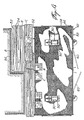
- Figure 1 is an end elevational view of the scaffolding in the elevated position next to a building wall to be covered with bricks.
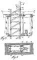
- Figure 2 is an end elevation view similar to that of Figure 1, but on an enlarged scale and with the working platform practically at ground level.
- Figure 3 is a side elevational view of the scaffolding.
- Figure 4 is a top plan view of the scaffolding.
- Figure 5 is a vertical section through a post and through the working platform.
- Figure 6 is a plan section taken along line 6-6 of Figure 5.
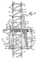
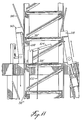
- Figures 7 to 11 are vertical sections similar to that of Figure 5, but showing the various members for lifting and lowering the platform along the post and showing the successive positions taken by these members.
- a rigid base 20 consisting of a central beam 22 and two transverse beams of ends 24 from each end of which protrudes down a foot or adjustable leveling disc, 26.
- four standing tubes 28 are fixed, arranged at the corners of a rectangle.
- Each group of four tubes 28 are arranged to support and fix a post 30.
- Each post consists of modular post sections, 32.
- Each post section consists of an open trellis frame having a rectangular section and comprising four angular members corner and elongated, 34, interconnected by inclined fasteners 36 and by transverse fasteners 37 along two opposite faces of each post and by transverse bars 38 along two other faces opposite of each post 30.
- each post section 32 When the post sections are interconnected one above the other, the transverse bars 38 are vertically equidistant and form anchor bearings.
- the lower end of the corner members 34 of each post section comprises a projecting plate 39 which can engage in the upper end of the corner members 34 of the immediately lower post section, these plates being anchored in place by transverse pins 40 passing through orifices in the overlapping parts, as shown in FIG. 5.
- Each post section 32 has such a length and width that it can be easily handled by a single worker, by means of 'a manual winch if necessary, on a work platform 42 suspended from the two posts. Therefore, the many post sections 32 can be carried by the working platform 42 and successively installed one above the other as the platform is being lifted and dismantled as and as the platform is lowered.
- the working platform 42 is generally rectangular in shape and comprises a main frame 44 directly supporting a floor 46, the frame 44 being reinforced below by a bottom frame 48. As illustrated in Figure 4, the working platform 42 has two openings 50 spaced along the central line of the working platform for the passage of the two posts 30.
- the frame 44 and the bottom frame 48 are made of two tubular metal members in which platform extension sections, 52, can be removably installed, at various levels, as shown in FIG. 2, and also in FIGS. 2 and 3 in the form of supports for support the floor 54 near a building wall 56 and which can be arranged to follow the outline of the building wall, as shown in plan section in FIG. 4, so as to allow a worker A to stand stand near the building wall and install a covering, for example bricks referenced B, using mortar C.
- the scaffolding can be installed sufficiently spaced from a building wall 56, so as to completely clear any protruding obstruction such as balconies D and the like.
- the platform extensions are temporarily removed to clear each balcony as the brick laying work progresses up the wall.
- balustrade or ramp 58 is removably installed on three sides of the platform as a safety measure. Part of this balustrade can be used as an opening door, as shown at 60 in Figures 3 and 4, to allow easier loading of the working platform when it is substantially at ground level. If desired, platform extensions can be installed at both ends of the main work platform, 42, to increase the width of the wall section accessible to workers.
- a flying bridge 62 is suspended under the working platform 42 by cables 64. Guard railings 66 are also connected to the cables 64. Also, vertical stabilization rods, 68, are fixed to the flying bridge 62 and carry a stop at their upper end. They are guided by sliding in sleeves 70 fixed to the working platform 42. The guide rods 68 stabilize the flywheel 62 laterally and longitudinally, and firmly stop the flying bridge at the desired level under the platform 42.
- This arrangement allows the flying bridge to rest on the base 20 immediately under the working platform 42 when the latter is in the fully lowered position, with its bottom frame 48 resting on the base 20 so that the platform completely lowered and the base can occupy a minimum of height when not used to facilitate their transport from one construction site to another.
- the flying bridge 62 carries posts 72 (FIG. 2) provided with stirrups 74 to support elongated spacers, not shown, to be installed by the worker, who has come down from the working platform on the flying bridge 62, so to attach the two posts to each other.
- These attachment bars are successively attached at the required height intervals, while the platform is being lifted, and are similarly detached from the posts when the platform is lowered, and the post sections successively undone.
- the attachment rods 76 supported by the hooks 64 are installed by the worker to attach the two posts to the building wall 56 while the platform is raised, so to stabilize the posts in the direction towards and outside the building wall.
- the tie rods 76 When the platform is lowered, the tie rods 76 are removed, again using the flybridge to access it. Eyelets 78 have been previously fixed to the wall 56 and a hook 80 fixed to one end of the tie rods 76 serves to engage the eyelets 78.
- the tie rods 76 are fixed to the posts 30 by adjustable connectors, 81.
- the working platform 42 is guided along the post 30 by two sets of rimmed guide rollers, 82, engaging the angular members 34 at the four corners of each post, one set at the working platform 42, and the other set of rim rollers 82 being carried by the bottom frame 48 vertically below the first set of rollers, so as to better stabilize the platform, transversely to the posts 30.
- FIG. 7 shows the means for suspending the platform from each pole and for raising or lowering the platform along the poles.
- An anchor arm 84 is disposed on one side of each post and is pivoted at 86 to the ears 88 fixed to the frame 44 of the working platform.
- the upper end of each arm 44 carries a hook 90, opening downwards, engaged in a removable manner with any of the transverse bars 38 of the pole sections 32 to suspend the platform there.
- the lower end of each arm 84 comprises a lateral arm 92 to which a tension spring 94 is attached, the other end of which is attached to a post 96 fixed to the platform 42.
- the spring 94 constantly forces the arm 84 towards the post 30.
- the lower end of a guide bar 98 inclined outwards and upwards is fixed to the hook 90.
- the guide bar 98 is at least at the level of the bar higher next 38 so as to slide on the latter when the platform is raised along the post, and allow the hook to hang on this last bar 38 under the stress of the spring.
- a second anchoring system consisting of an arm 84 ', a pivot 86', ears 88 ', a hook 90', a lateral arm 92 ', a tension spring 94 'and a guide bar 98' is installed on the bottom frame 48 vertically below the first anchoring system, so that the two hooks 90, 90 ′ can engage different transverse bars at the same time, as shown in FIG. 7.
- This FIG. 7 also shows manual actuation means for pivoting at distance the lower arms 84 ′ outwards, so as to release the transverse notches 38 from the two posts during the lowering of the platform.
- These means comprise a side arm 100 fixed to the lower arm 84 'and connected by a connecting rod 102 to an actuating lever 104 pivoted to the working platform 42 in a position accessible to the worker on the platform, to release the lower hook.
- the upper hook can be released by pulling out the guide bar 98 when releasing the notch 38 as shown in FIG. 9.
- the other anchoring member of the pair is shown at 106 in FIG. 7, it is actuated by force; it can lengthen and retract longitudinally, so as to raise or lower the platform in relation to the posts.
- the extendable member 106 comprises a double-action hydraulic cylinder 108 pivoted at its lower end 110 to the bottom frame 48 of the work platform and extending upwards thereof through the opening 50 of the work platform. job.
- the jack 108 has a piston rod 112 extending towards the high from the platform and the upper end of which is pivoted at 114 to the rigid arm 116, the upper end of which is fixed to a hook opening downwards, 118, similar to the hook 90, and which is also provided a guide bar inclined outwards and upwards, 120, similar to guide bar 98 and for the same purpose.
- a support 122 is fixed to the upper end of the piston rod 112, said support carrying the pivot 114 and also a guide rod 124 which extends downwards, parallel to the piston rod 112, and which is guided in a sleeve 126 fixed to the upper end of the cylinder of the jack 108.
- the pivot 110 of the lower end of the jack 108 is sufficiently spaced from the post 130 so that the center of gravity of the jack and the hook system are always between the pivot 110 and the post. This therefore constitutes a means of constantly and automatically constraining the hook 118 against the post, so as to cause automatic engagement of the hook 118 with a transverse bar 38 when the platform is being lowered or raised.
- the stroke of the jack 108 is at least slightly more than the vertical spacing between two adjacent notch bars 38 of the post 30; but, in practice, the stroke is a little more than the distance between three notch bars, so as to raise or lower the platform by two notches for a single stroke of the jack 108, thereby accelerating the lowering or lifting procedure.
- the hook 90 only suspends the working platform.
- the hook 118 is raised by the piston rod 112 from its position in dotted lines to a position slightly above the second highest notch bar 38, then after slightly lowered to engage the last mentioned notch.
- the whole platform is raised; the hook 90 releases the next two higher notches ( Figures 8-9) until the piston rod 112 is fully retracted, at which position the hook 90 is slightly higher and releases the adjacent notch bar.
- the piston rod 112 is slightly extended to substantially lower the platform and force the hook 90 to fully engage the adjacent catch bar 38, as shown in FIG. 10.
- the platform is suspended securely and the cycle is repeated .
- the lowering of the platform is also carried out two notches at a time, as shown in FIG. 11.
- we proceed as follows after having slightly raised the platform 42 so that the hook 90 releases the notch 38 '', and after having pulled on the guide bar 98, a plate 128 is temporarily suspended from the notches 38 'and 38''so that the hook 90 engages only the 38 '' notch.
- the lever 104 is actuated to allow the hook 90 'to be released.
- the two hooks 90 ' can be interconnected from one post to the other, so that a single lever 104 can operate the two lower hooks.
- the arm 116 of the jack 108 is pivoted at 114 to the support 122 to prevent any stress on the piston rod 112 during its movement in the body of the jack 108.
- the arm 116 remains simply pressed on the post 30 and when the arm is under tension, the piston rod automatically aligns with said arm.
- a spiral spring is arranged at the pivot 114 in order to constantly constrain the arm 116 towards the post 30.
- the two jacks 108 are connected by a hydraulic circuit, including the tube 130 ( Figure 10), to a hydraulic pump (not shown) located in a box 132 ( Figure 3) installed on the working platform 42, in the vicinity of a pole 30.
- the box 132 also contains an internal combustion engine for driving the hydraulic pump.
- the hydraulic circuit is controlled by hydraulic valves (not shown) actuated by means of control levers 134 by the worker standing on the platform.
- a single worker can handle the entire lifting and lowering procedure of the platform, including the installation of pole sections 32, as the platform is raised; their removal as the platform is lowered and including the descent on the flying bridge 62 and the installation or removal of the spacers connecting the two posts and tie rods 76 connecting each post to the adjacent wall 56 .
- the platform is strong enough and the hydraulic system is powerful enough to lift a platform, including the required number of workers, the total load of bricks and mortar sufficient for laying bricks for a multi-storey building on a width equivalent to the length of the work platform and even on an extension thereof. If additional building materials are required, a winch system can be installed on the work platform to lift them.
- the scaffolding is quickly installed and dismantled, and when completely dismantled, occupies a reduced space to facilitate its transport to another construction site.
- a set of wheels can be installed at 136 ( Figure 3) at the bottom frame and a towing device can be installed at 138 at the opposite end, so that the scaffolding can be easily pulled by a tractor-trailer such as a semi-trailer, the platform being completely lowered to the base 20 and the latter being blocked under the platform.
- a tractor-trailer such as a semi-trailer
Landscapes
- Engineering & Computer Science (AREA)
- Architecture (AREA)
- Mechanical Engineering (AREA)
- Civil Engineering (AREA)
- Structural Engineering (AREA)
- Movable Scaffolding (AREA)
- Lubricants (AREA)
- On-Site Construction Work That Accompanies The Preparation And Application Of Concrete (AREA)
- Ladders (AREA)
- Conveying And Assembling Of Building Elements In Situ (AREA)
- Chairs Characterized By Structure (AREA)
- Fluid-Pressure Circuits (AREA)
Claims (6)
- Gerüst mit einer Grundfläche (20), einem Paar in einem Abstand zueinander angeordneter Ständer (30), die an der Grundfläche überstehend befestigt sind, wobei jeder Ständer aus modularen Ständerabschnitten (32) besteht, Verbindungsmitteln (39, 40), um die Ständerabschnitte lösbar, nacheinander und übereinander befestigen zu können, wobei die Ständer annähernd abstandsgleiche Stufenmittel (38) darstellen, einer von den Ständern (30) abgestützten Arbeitsbühne (42), die bezogen auf die Ständer angehoben und abgesenkt werden kann, einem Paar Verankerungsorganen (84, 116), die schwenkbar an der Bühne im Bereich jedes Ständers gelagert sind und abwechselnd nacheinander mit den Stufenmitteln verbunden werden können, um die Arbeitsbühne an den Ständern in unterschiedlicher Höhe aufzuhängen, den Verankerungsorganen zugeordneten Zwangsmitteln zur automatischen Verbindung der Verankerungsorgane mit den Stufenmitteln, wenn die Bühne angehoben oder abgesenkt wird, wobei die Ständerabschnitte (32) so angeordnet sind, daß sie von einem einzigen Arbeiter auf der Bühne an den höchsten Ständerabschnitten befestigt oder von diesen abgenommen werden können, wenn sich die Bühne in der allgemeinen Höhe der höchsten Ständerabschnitte befindet,
dadurch gekennzeichnet, daß mindestens ein Verankerungsorgan (116) des Paares ein zwangsgesteuertes Organ (106) ist, das in Längsrichtung der Ständer im Vergleich zur Arbeitsplattform über einen Hub, der mindestens gleich dem vertikalen Abstand zwischen den benachbarten Stufenmitteln ist, ein- und ausgefahren werden kann, wobei die Bühne (42) durch die ausfahrbaren Organe angehoben und abgesenkt werden kann, daß das andere Organ (84) der Paare abwechselnd die Stufenmittel verbindet, um die Bühne aufzuhängen, wenn diese von den ausfahrbaren Organen der Paare angehoben oder abgesenkt wird, und daß ein Hängegerüst (62), dessen Länge mindestens gleich dem Abstand zwischen den beiden Ständern ist, über Hängekabel (64) unter der Bühne (42) in einer Lage aufgehängt ist, daß ein Arbeiter von der Bühne auf das Hängegerüst heruntersteigen kann, um Zugang zu den beiden Ständern zu haben, damit er sie über Streben miteinander verbinden kann. - Gerüst nach Anspruch 1,
dadurch gekennzeichnet, daß die Arbeitsbühne (42) jeden Ständer (30) umgibt, und dadurch, daß sie Verbindungsstangen (76) hat, die an einem Ende mit einem Haken (80) und am anderen Ende mit einer Kupplung (81) versehen sind und die dazu dienen, die Ständer mit einer Gebäudemauer, an der die Ständer aufgestellt sind, zu verbinden, wobei das Hängegerüst Bügel (74) hat, um die Verbindungsstangen (76) bei der Lagerung zu halten, und die Verbindungsstangen mit den Ständern und der Mauer durch einen Arbeiter auf dem Hängegerüst verbunden werden können. - Gerüst nach Anspruch 2,
dadurch gekennzeichnet, daß es Führungsmittel (68, 70) hat, die verhindern, daß das Hängegerüst (62) am Ende seiner Hängekabel (64) ins Schwingen gerät, und die in Transportstellung des Gerüsts, in der die Bühne auf der Grundfläche (20) aufliegt, die Anordnung des Hängegerüsts unter der Bühne ermöglichen. - Gerüst nach einem der Ansprüche 1 oder 2,
dadurch gekennzeichnet, daß das zwangsgesteuerte Organ (106) einen Hydraulikzylinder (108) hat, dessen unteres Ende schwenkbar (110) an der Bühne angebracht ist und dessen oberes Ende der Kolbenstange (112) mit einem Haken (116, 118) versehen ist, der nacheinander in die Verankerungsstufe (38) der Ständer (30) eingehakt werden kann, wobei ein Führungsarm (120) am oberen Ende des Hakens (116, 118) befestigt ist und sich bezogen auf den Ständer nach oben außen über die nächsthöhere Verankerungsstufe fortsetzt, wenn der Haken in eine Verankerungsstufe (38) eingehakt ist, wobei sich die Gesamtheit Zylinder-Haken auf der gleichen Seite des Ständers befindet, der Schwerpunkt der Gesamtheit zwischen dem Ständer und dem Drehzapfengelenk des Zylinders an der Bühne liegt und so ein Zwangsmittel darstellt, das die automatische Verbindung des Hakens mit der einen oder anderen der Verankerungsstufen bewirkt, wobei die Führungsstange gegen die Verankerungsstufen gleitet, um den Haken in seiner Aufwärtsbewegung beim Einhaken zu führen. - Gerüst nach Anspruch 4,
dadurch gekennzeichnet, daß die Verankerungsmittel einen Haken (84, 90) haben, der an jedem Ständer in Längsrichtung angebracht ist und an seinem unteren Ende (86) an der Arbeitsbühne (42) schwenkbar gelagert ist und ebenfalls eine Führungsstange (98) hat, die sich bezogen auf den Ständer nach oben außen fortsetzt, wobei der Haken (84, 90) dazu dient, die Bühne am Ständer aufzuhängen, wenn der Hydraulikzylinder nicht in Funktion ist, und Zwangsmittel, die den Haken (84, 90) gegen den Ständer schwenken, so daß die Führungsstange (98) an den Verankerungsstufen (38) entlang gleiten kann. - Gerüst nach Anspruch 5,
dadurch gekennzeichnet, daß der Haken (116, 118) mit seinem unteren Ende am oberen Ende der Kolbenstange (112) schwenkbar gelagert ist und daß er außerdem eine Führungsstange (124) hat, die in einer Muffe (126) gleitet, die am Gehäuse des Zylinders (108) befestigt ist, wobei das obere Ende der Führungsstange (124) mit dem oberen Ende der Kolbenstange (112) verbunden ist, um eine Drehung der Kolbenstange und demzufolge des Hakens (116, 118) nach der Längsachse des Hydraulikzylinders (108) zu verhindern.
Applications Claiming Priority (2)
| Application Number | Priority Date | Filing Date | Title |
|---|---|---|---|
| US07/177,539 US4809814A (en) | 1988-04-01 | 1988-04-01 | Scaffolding |
| US177539 | 2002-06-21 |
Publications (3)
| Publication Number | Publication Date |
|---|---|
| EP0335311A2 EP0335311A2 (de) | 1989-10-04 |
| EP0335311A3 EP0335311A3 (en) | 1990-12-05 |
| EP0335311B1 true EP0335311B1 (de) | 1994-06-01 |
Family
ID=22648993
Family Applications (1)
| Application Number | Title | Priority Date | Filing Date |
|---|---|---|---|
| EP89105421A Expired - Lifetime EP0335311B1 (de) | 1988-04-01 | 1989-03-28 | Hydraulisches Gerüst |
Country Status (4)
| Country | Link |
|---|---|
| US (1) | US4809814A (de) |
| EP (1) | EP0335311B1 (de) |
| AT (1) | ATE106491T1 (de) |
| DE (1) | DE68915599T2 (de) |
Families Citing this family (48)
| Publication number | Priority date | Publication date | Assignee | Title |
|---|---|---|---|---|
| FR2615227B1 (fr) * | 1987-05-12 | 1989-06-30 | Duez Alain | Dispositif de transport et de distribution de materiaux et/ou de materiel en peripherie d'un batiment |
| US5067587A (en) * | 1990-12-28 | 1991-11-26 | William F. Mims, Jr. | Service platform for mobile scaffolding unit |
| US5159993A (en) * | 1991-10-15 | 1992-11-03 | Gestion Des Brevets Fraco Limitee | Self-raising work platform assembly |
| US5259479A (en) * | 1991-10-15 | 1993-11-09 | Gestion Des Brevets Fraco Ltee | Self-raising cantilever-type work platform assembly |
| US5368125A (en) * | 1993-04-16 | 1994-11-29 | St-Germain; Andre | Platform raising system in scaffolding |
| DE9310342U1 (de) * | 1993-07-12 | 1993-09-30 | FAC Frank Abels Consulting & Technology GmbH, 29633 Munster | Höhenverstellbares Arbeitsgerüst, insbesondere für den Einsatz auf Baustellen |
| US5579865A (en) * | 1994-02-23 | 1996-12-03 | Butler; J. Frank | Scaffold |
| US5636705A (en) * | 1995-05-24 | 1997-06-10 | St-Germain; Andre | Apparatus for moving a work platform along a rail |
| US5746290A (en) * | 1995-07-27 | 1998-05-05 | Gestion De Brevets Fraco Ltee | Self erecting scaffolding |
| US6186273B1 (en) * | 1997-02-19 | 2001-02-13 | Metro Machine Corporation | Self-contained staging system for cleaning and painting bulk cargo holds |
| US6102157A (en) * | 1997-02-19 | 2000-08-15 | Metro Machine Corporation | Self-contained staging system for cleaning and painting bulk cargo holds |
| BR9714660A (pt) * | 1997-05-05 | 2000-07-11 | Prod Fraco Ltee | Sistema de içamento de plataforma e andaime |
| SE9801065D0 (sv) * | 1998-03-27 | 1998-03-27 | Alimak Ab | Anordning vid kuggstångsdrivna hissar, byggplattformar eller liknande |
| CA2242128A1 (en) * | 1998-06-29 | 1999-12-29 | Mmc Compliance Engineering, Inc. | Self-contained device for cleaning and coating hold surfaces in a bulk carrier |
| CA2281737A1 (en) | 1999-09-09 | 2001-03-09 | Jean G. Robillard | Self-raising, caterpillar-driven platform assembly |
| CA2317987A1 (en) * | 2000-09-11 | 2002-03-11 | Jean G. Robillard | Improved self-raising platform assembly |
| IT1315749B1 (it) * | 2000-10-12 | 2003-03-18 | C M S Srl | Struttura di ponteggio mobile |
| US6523647B2 (en) | 2001-05-21 | 2003-02-25 | Hydro Mobile Inc. | Elevating platform assembly |
| SE526546C2 (sv) * | 2004-03-12 | 2005-10-04 | Alimak Ab | Hissystem |
| DE102004052284B4 (de) * | 2004-10-27 | 2008-01-10 | Hünnebeck GmbH | Hochwasserlaufsteg |
| US20070000724A1 (en) * | 2005-06-29 | 2007-01-04 | Sky Climber Llc | Self-erecting suspension platform system |
| DE102005030335A1 (de) * | 2005-06-29 | 2007-01-04 | Peri Gmbh | Kletterzylinder einer Selbstkletterschalung |
| US8302735B2 (en) | 2005-06-29 | 2012-11-06 | Sky Climber, Llc | Self-erecting suspension platform system |
| DE102005030332A1 (de) * | 2005-06-29 | 2007-01-04 | Peri Gmbh | Angelenkter Kletterschuh einer Kletterschalung |
| US7168904B1 (en) | 2005-08-26 | 2007-01-30 | James Cameron Perkins | Portable vehicle storage platform |
| US20070056802A1 (en) * | 2005-09-13 | 2007-03-15 | Joseph Taberah | Scaffolding |
| WO2007082222A1 (en) * | 2006-01-12 | 2007-07-19 | Putzmeister Inc. | Pumping tower support system and method of use |
| US7896133B2 (en) * | 2006-02-17 | 2011-03-01 | Jerry Castle | Self-elevating platform scaffolding |
| US20070204520A1 (en) * | 2006-03-01 | 2007-09-06 | Calleja Michael J | Self-elevating staging with rack-and-pinion posts |
| CA2602739C (en) * | 2007-09-14 | 2016-04-12 | Joseph Taberah | Power lift system |
| US8167089B2 (en) * | 2008-01-15 | 2012-05-01 | Bennu Parts And Service, Inc. | Liftable scaffold |
| US20100025152A1 (en) * | 2008-08-01 | 2010-02-04 | Kuseski Christopher A | Scaffolding platform with materials ledge |
| BE1019424A5 (nl) * | 2010-07-16 | 2012-07-03 | Keersmaekers Marc | Liftsysteem voor een steiger. |
| EP2593391B1 (de) * | 2010-07-16 | 2017-05-31 | Marc Keersmaekers | Hebeeinheit zum heben udn senken eines gerüsts |
| WO2012006694A1 (en) * | 2010-07-16 | 2012-01-19 | Marc Keersmaekers | Lift system for use in a scaffold |
| BE1019305A5 (nl) * | 2010-07-16 | 2012-05-08 | Keersmaekers Marc | Een lifteenheid voor een steiger, werkwijzen om met de lifteenheid te stijgen en af te dalen in een steiger, werkwijzen om een steiger op te bouwen, en werkwijzen om een steigen af the breken. |
| JP2013170371A (ja) * | 2012-02-20 | 2013-09-02 | Akihiro Fukada | 作業足場及びその組立工法 |
| EP2820365B1 (de) * | 2012-03-01 | 2019-08-14 | Evapco, Inc. | Verfahren und vorrichtung zur montage vor ort aufgebauter kühlturmrahmen |
| CA2834094C (en) * | 2012-11-23 | 2019-08-20 | Fiducie Familiale Andre St-Germain | Self-contained, portable and self-supporting scaffolding kit |
| US9145956B2 (en) | 2013-01-25 | 2015-09-29 | Gustomsc Resources B.V. | Torque sharing drive and torque sharing process |
| US10072465B1 (en) * | 2013-03-15 | 2018-09-11 | Integris Rentals, L.L.C. | Containment work platform |
| US9531237B2 (en) | 2013-12-19 | 2016-12-27 | Gustomsc Resources B.V. | Dual rack output pinion drive |
| CN103967050B (zh) * | 2014-01-29 | 2015-05-20 | 广州机施建设集团有限公司 | 一种地铁车站的施工方法 |
| CN103979383B (zh) * | 2014-04-29 | 2016-03-16 | 山东腾飞建设机械工程有限公司 | 建筑施工多层升降平台系统 |
| US10465401B2 (en) * | 2015-04-15 | 2019-11-05 | Ronald A. Bullock | Construction safety net support apparatus |
| US20180179767A1 (en) | 2016-12-28 | 2018-06-28 | Curt Wylde | Scaffold extensions |
| US20250019983A1 (en) * | 2023-07-12 | 2025-01-16 | Thomas M. Anderson | Mast mounted screed boom |
| US20250223816A1 (en) * | 2024-01-05 | 2025-07-10 | Klimer Platforms Inc. | Mast climbing work platform with translating function and related method |
Family Cites Families (15)
| Publication number | Priority date | Publication date | Assignee | Title |
|---|---|---|---|---|
| US1168868A (en) * | 1910-04-04 | 1916-01-18 | Henry Ericsson | Adjustable scaffold. |
| US2616769A (en) * | 1947-12-29 | 1952-11-04 | Nelson H Rector | Elevating ladder scaffold |
| US2947148A (en) * | 1954-06-28 | 1960-08-02 | Sun Oil Co | Jacking mechanism for seadrome |
| US2851125A (en) * | 1957-09-27 | 1958-09-09 | Universal Mfg Co | Scaffold platform elevator |
| US3318414A (en) * | 1965-08-30 | 1967-05-09 | Ralph L Meek | Scaffolding |
| US3323616A (en) * | 1965-10-22 | 1967-06-06 | Frank S Best | Mason's scaffold |
| US3466723A (en) * | 1965-11-10 | 1969-09-16 | Richier Sa | Methods for erecting tower cranes |
| US3438460A (en) * | 1966-11-09 | 1969-04-15 | Louis J Solari | Scaffold with elevatable section |
| US3610368A (en) * | 1969-10-15 | 1971-10-05 | Harold R Johnson | Vertically adjustable platform for scaffolding |
| DE2342630A1 (de) * | 1973-08-23 | 1975-03-13 | Erwin Maul | Geruest zur herstellung eines gebaeudes |
| FR2261387A1 (en) * | 1974-02-18 | 1975-09-12 | Petralli Jean Marie | Hand operated overhead working platform - winding gear inside cage, guide rollers steady descent, cage carries hooked arms for safety |
| FR2355764A1 (fr) * | 1976-05-11 | 1978-01-20 | Potain Sa | Procede et dispositif pour le telescopage de la tour d'une grue |
| US4294332A (en) * | 1979-04-13 | 1981-10-13 | Ready Delbert L | Scaffold with gear drive |
| US4293054A (en) * | 1980-05-19 | 1981-10-06 | Piat Impalcature Automatiche S.P.A. | Scaffolding for supporting lifting working bridges and platforms |
| US4641728A (en) * | 1985-03-22 | 1987-02-10 | Mccabe Raymond T | Scaffold system |
-
1988
- 1988-04-01 US US07/177,539 patent/US4809814A/en not_active Expired - Lifetime
-
1989
- 1989-03-28 DE DE68915599T patent/DE68915599T2/de not_active Expired - Lifetime
- 1989-03-28 AT AT89105421T patent/ATE106491T1/de not_active IP Right Cessation
- 1989-03-28 EP EP89105421A patent/EP0335311B1/de not_active Expired - Lifetime
Also Published As
| Publication number | Publication date |
|---|---|
| EP0335311A3 (en) | 1990-12-05 |
| US4809814A (en) | 1989-03-07 |
| EP0335311A2 (de) | 1989-10-04 |
| DE68915599T2 (de) | 1994-09-15 |
| ATE106491T1 (de) | 1994-06-15 |
| DE68915599D1 (de) | 1994-07-07 |
Similar Documents
| Publication | Publication Date | Title |
|---|---|---|
| EP0335311B1 (de) | Hydraulisches Gerüst | |
| US9410329B2 (en) | Lift unit for ascending and descending a scaffold | |
| EP1766157A1 (de) | Plattformstützvorrichtung zum anheben von lasten oder personen über die höhe einer struktur | |
| JP2000288111A (ja) | 安全帯取付け装置 | |
| EP0468907A1 (de) | Zusammenklappbare Stutz-Konsole für Wandschalungen | |
| FR2794149A1 (fr) | Amelioration concernant un appareil pour un systeme de battage a verins incorpores | |
| FR2487410A1 (fr) | Coffrage grimpant pour la coulee de parois en beton | |
| EP0182727A2 (de) | Hebevorrichtung | |
| WO1999023329A1 (fr) | Procede d'installation d'un echafaudage suspendu a une façade d'un batiment et systeme pour la mise en oeuvre de ce procede | |
| EP0612899B1 (de) | Gerüstboden und Montageverfahren für Gerüste mit diesem Boden | |
| KR102560294B1 (ko) | 로프 결박이 가능한 구조 개선된 건설 자재 리프트 장치 | |
| FR2510164A1 (fr) | Passerelle a consoles pliables pour travaux de batiments | |
| FR2632349A1 (fr) | Plate-forme de travail adaptable aux echelles | |
| EP0874108A1 (de) | Vorrichtung zum ungefährlichen Montieren von Gerüsten | |
| JP5476051B2 (ja) | 基台および昇降式移動足場 | |
| EP2085537B1 (de) | Sicherheitsmontage- und -demontageverfahren eines fahrbaren Gerüsts, die dabei verwendeten Sicherheitsmontageprofile und das so erhaltene Gerüst | |
| CA1304109C (fr) | Echafaudage hydraulique | |
| EP0330642B1 (de) | Leiterfahrkorb | |
| JP2000320132A (ja) | 足場用荷揚機 | |
| KR102835155B1 (ko) | 수레형 맨홀뚜껑 개방이동장치 및 설치방법 | |
| JP2008095373A (ja) | 移動用足場およびその仮設方法 | |
| FR2831578A1 (fr) | Dispositif formant echafaudage suspendu a une facade d'un batiment | |
| JP2872419B2 (ja) | 塔状構造体の組立方法及び該方法に用いる昇降足場装置 | |
| FR2572448A1 (fr) | Echafaudage. | |
| CH372809A (fr) | Monte-matériaux vertical |
Legal Events
| Date | Code | Title | Description |
|---|---|---|---|
| PUAI | Public reference made under article 153(3) epc to a published international application that has entered the european phase |
Free format text: ORIGINAL CODE: 0009012 |
|
| AK | Designated contracting states |
Kind code of ref document: A2 Designated state(s): AT BE CH DE ES FR GB GR IT LI LU NL SE |
|
| PUAL | Search report despatched |
Free format text: ORIGINAL CODE: 0009013 |
|
| AK | Designated contracting states |
Kind code of ref document: A3 Designated state(s): AT BE CH DE ES FR GB GR IT LI LU NL SE |
|
| 17P | Request for examination filed |
Effective date: 19901213 |
|
| 17Q | First examination report despatched |
Effective date: 19910916 |
|
| RAP1 | Party data changed (applicant data changed or rights of an application transferred) |
Owner name: AVANT-GARDE ENGINEERING INC. |
|
| GRAA | (expected) grant |
Free format text: ORIGINAL CODE: 0009210 |
|
| AK | Designated contracting states |
Kind code of ref document: B1 Designated state(s): AT BE CH DE ES FR GB GR IT LI LU NL SE |
|
| PG25 | Lapsed in a contracting state [announced via postgrant information from national office to epo] |
Ref country code: IT Free format text: LAPSE BECAUSE OF FAILURE TO SUBMIT A TRANSLATION OF THE DESCRIPTION OR TO PAY THE FEE WITHIN THE PRE;WARNING: LAPSES OF ITALIAN PATENTS WITH EFFECTIVE DATE BEFORE 2007 MAY HAVE OCCURRED AT ANY TIME BEFORE 2007. THE CORRECT EFFECTIVE DATE MAY BE DIFFERENT FROM THE ONE RECORDED.SCRIBED TIME-LIMIT Effective date: 19940601 Ref country code: NL Effective date: 19940601 Ref country code: AT Effective date: 19940601 Ref country code: ES Free format text: THE PATENT HAS BEEN ANNULLED BY A DECISION OF A NATIONAL AUTHORITY Effective date: 19940601 Ref country code: GR Free format text: LAPSE BECAUSE OF FAILURE TO SUBMIT A TRANSLATION OF THE DESCRIPTION OR TO PAY THE FEE WITHIN THE PRESCRIBED TIME-LIMIT Effective date: 19940601 |
|
| REF | Corresponds to: |
Ref document number: 106491 Country of ref document: AT Date of ref document: 19940615 Kind code of ref document: T |
|
| REF | Corresponds to: |
Ref document number: 68915599 Country of ref document: DE Date of ref document: 19940707 |
|
| GBT | Gb: translation of ep patent filed (gb section 77(6)(a)/1977) |
Effective date: 19940610 |
|
| PG25 | Lapsed in a contracting state [announced via postgrant information from national office to epo] |
Ref country code: SE Effective date: 19940901 |
|
| NLV1 | Nl: lapsed or annulled due to failure to fulfill the requirements of art. 29p and 29m of the patents act | ||
| PG25 | Lapsed in a contracting state [announced via postgrant information from national office to epo] |
Ref country code: LI Effective date: 19950331 Ref country code: LU Free format text: LAPSE BECAUSE OF NON-PAYMENT OF DUE FEES Effective date: 19950331 Ref country code: CH Effective date: 19950331 |
|
| PLBE | No opposition filed within time limit |
Free format text: ORIGINAL CODE: 0009261 |
|
| STAA | Information on the status of an ep patent application or granted ep patent |
Free format text: STATUS: NO OPPOSITION FILED WITHIN TIME LIMIT |
|
| 26N | No opposition filed | ||
| REG | Reference to a national code |
Ref country code: CH Ref legal event code: PL |
|
| REG | Reference to a national code |
Ref country code: GB Ref legal event code: 732E |
|
| REG | Reference to a national code |
Ref country code: FR Ref legal event code: TP |
|
| REG | Reference to a national code |
Ref country code: GB Ref legal event code: 732E |
|
| REG | Reference to a national code |
Ref country code: FR Ref legal event code: GC |
|
| REG | Reference to a national code |
Ref country code: GB Ref legal event code: IF02 |
|
| PGFP | Annual fee paid to national office [announced via postgrant information from national office to epo] |
Ref country code: DE Payment date: 20080407 Year of fee payment: 20 |
|
| PGFP | Annual fee paid to national office [announced via postgrant information from national office to epo] |
Ref country code: FR Payment date: 20080331 Year of fee payment: 20 |
|
| PGFP | Annual fee paid to national office [announced via postgrant information from national office to epo] |
Ref country code: GB Payment date: 20080402 Year of fee payment: 20 |
|
| PGFP | Annual fee paid to national office [announced via postgrant information from national office to epo] |
Ref country code: BE Payment date: 20080701 Year of fee payment: 20 |
|
| BE20 | Be: patent expired |
Owner name: *AVANT-GARDE ENGINEERING (1994) INC. Effective date: 20090328 |
|
| REG | Reference to a national code |
Ref country code: GB Ref legal event code: PE20 Expiry date: 20090327 |
|
| PG25 | Lapsed in a contracting state [announced via postgrant information from national office to epo] |
Ref country code: GB Free format text: LAPSE BECAUSE OF EXPIRATION OF PROTECTION Effective date: 20090327 |