EP0335311B1 - Hydraulic scaffold - Google Patents
Hydraulic scaffold Download PDFInfo
- Publication number
- EP0335311B1 EP0335311B1 EP89105421A EP89105421A EP0335311B1 EP 0335311 B1 EP0335311 B1 EP 0335311B1 EP 89105421 A EP89105421 A EP 89105421A EP 89105421 A EP89105421 A EP 89105421A EP 0335311 B1 EP0335311 B1 EP 0335311B1
- Authority
- EP
- European Patent Office
- Prior art keywords
- platform
- posts
- post
- hook
- anchoring
- Prior art date
- Legal status (The legal status is an assumption and is not a legal conclusion. Google has not performed a legal analysis and makes no representation as to the accuracy of the status listed.)
- Expired - Lifetime
Links
Images


Classifications
-
- E—FIXED CONSTRUCTIONS
- E04—BUILDING
- E04G—SCAFFOLDING; FORMS; SHUTTERING; BUILDING IMPLEMENTS OR AIDS, OR THEIR USE; HANDLING BUILDING MATERIALS ON THE SITE; REPAIRING, BREAKING-UP OR OTHER WORK ON EXISTING BUILDINGS
- E04G1/00—Scaffolds primarily resting on the ground
- E04G1/18—Scaffolds primarily resting on the ground adjustable in height
- E04G1/20—Scaffolds comprising upright members and provision for supporting cross-members or platforms at different positions therealong
Definitions
- the invention relates to scaffolding and, more particularly, to a scaffolding arranged so as to be installed along a building wall for use by workers during the installation of a covering on this wall, by example a brick facing.
- a scaffolding comprising a base; a pair of spaced posts, attached to, and projecting from the base, each post being formed of modular post sections; fastening means for detachably and successively fixing said sections of posts one above the other, said posts defining bearing means which are substantially equidistant; a work platform surrounding said posts and capable of being raised and lowered with respect to said posts; a pair of anchoring members pivotally carried by said platform adjacent to each post, and alternately and successively engaging with said posts to suspend said working platform from said posts at different levels; at least one member controlled by force, said platform being able to rise and descend by said members controlled by force; restraint means associated with said anchoring members for causing automatic engagement of said anchoring members with said posts when said platform is raised or lowered; the other anchoring member of said pairs alternately engaging said posts to suspend said platform when the latter is raised or lowered by the members controlled by force; said pole sections being arranged so that they can be fixed or removed by
- document DE-A-2 342 630 relates to a scaffolding provided with a lifting member which can be a rack or a jack.
- the main object of the present invention is to make a scaffold, having means allowing a worker working on the platform to install the modular sections of posts and fasteners for the posts and tie rods from the posts. towards the building wall to stabilize the posts as the platform is raised and to allow the installation of scaffolding at a sufficient distance from the building wall to clear balconies and others that can make protrusion from the wall of the building.
- Another object of the present invention lies in new means for lifting and lowering the platform and its load along the posts.
- the scaffolding comprising a base, a pair of spaced-apart posts fixed to and projecting from said base, each post being formed of modular post sections, fastening means for detachably fixing and successive said sections of posts one above the other, said posts defining substantially equidistant bearing means, a working platform supported by said posts and capable of being raised and lowered with respect to said posts, a pair of anchoring members, pivotally carried by said platform adjacent to each post, and alternately and successively engaging with said bearing means, for suspending said platform working from said posts at different levels, constraint means associated with said anchoring members, to cause automatic engagement of said anchoring members with said bearing means when said platform is raised or lowered, said post sections being arranged so that they can be fixed or removed by a single worker on said platform on or from the highest pole sections, when said platform is at the general level of said highest pole sections, is characterized by the fact that at least one anchoring member of said pair is a force-controlled member which can be extended and retracted along
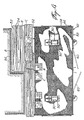
- Figure 1 is an end elevational view of the scaffolding in the elevated position next to a building wall to be covered with bricks.
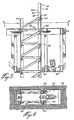
- Figure 2 is an end elevation view similar to that of Figure 1, but on an enlarged scale and with the working platform practically at ground level.
- Figure 3 is a side elevational view of the scaffolding.
- Figure 4 is a top plan view of the scaffolding.
- Figure 5 is a vertical section through a post and through the working platform.
- Figure 6 is a plan section taken along line 6-6 of Figure 5.
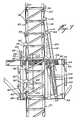
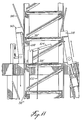
- Figures 7 to 11 are vertical sections similar to that of Figure 5, but showing the various members for lifting and lowering the platform along the post and showing the successive positions taken by these members.
- a rigid base 20 consisting of a central beam 22 and two transverse beams of ends 24 from each end of which protrudes down a foot or adjustable leveling disc, 26.
- four standing tubes 28 are fixed, arranged at the corners of a rectangle.
- Each group of four tubes 28 are arranged to support and fix a post 30.
- Each post consists of modular post sections, 32.
- Each post section consists of an open trellis frame having a rectangular section and comprising four angular members corner and elongated, 34, interconnected by inclined fasteners 36 and by transverse fasteners 37 along two opposite faces of each post and by transverse bars 38 along two other faces opposite of each post 30.
- each post section 32 When the post sections are interconnected one above the other, the transverse bars 38 are vertically equidistant and form anchor bearings.
- the lower end of the corner members 34 of each post section comprises a projecting plate 39 which can engage in the upper end of the corner members 34 of the immediately lower post section, these plates being anchored in place by transverse pins 40 passing through orifices in the overlapping parts, as shown in FIG. 5.
- Each post section 32 has such a length and width that it can be easily handled by a single worker, by means of 'a manual winch if necessary, on a work platform 42 suspended from the two posts. Therefore, the many post sections 32 can be carried by the working platform 42 and successively installed one above the other as the platform is being lifted and dismantled as and as the platform is lowered.
- the working platform 42 is generally rectangular in shape and comprises a main frame 44 directly supporting a floor 46, the frame 44 being reinforced below by a bottom frame 48. As illustrated in Figure 4, the working platform 42 has two openings 50 spaced along the central line of the working platform for the passage of the two posts 30.
- the frame 44 and the bottom frame 48 are made of two tubular metal members in which platform extension sections, 52, can be removably installed, at various levels, as shown in FIG. 2, and also in FIGS. 2 and 3 in the form of supports for support the floor 54 near a building wall 56 and which can be arranged to follow the outline of the building wall, as shown in plan section in FIG. 4, so as to allow a worker A to stand stand near the building wall and install a covering, for example bricks referenced B, using mortar C.
- the scaffolding can be installed sufficiently spaced from a building wall 56, so as to completely clear any protruding obstruction such as balconies D and the like.
- the platform extensions are temporarily removed to clear each balcony as the brick laying work progresses up the wall.
- balustrade or ramp 58 is removably installed on three sides of the platform as a safety measure. Part of this balustrade can be used as an opening door, as shown at 60 in Figures 3 and 4, to allow easier loading of the working platform when it is substantially at ground level. If desired, platform extensions can be installed at both ends of the main work platform, 42, to increase the width of the wall section accessible to workers.
- a flying bridge 62 is suspended under the working platform 42 by cables 64. Guard railings 66 are also connected to the cables 64. Also, vertical stabilization rods, 68, are fixed to the flying bridge 62 and carry a stop at their upper end. They are guided by sliding in sleeves 70 fixed to the working platform 42. The guide rods 68 stabilize the flywheel 62 laterally and longitudinally, and firmly stop the flying bridge at the desired level under the platform 42.
- This arrangement allows the flying bridge to rest on the base 20 immediately under the working platform 42 when the latter is in the fully lowered position, with its bottom frame 48 resting on the base 20 so that the platform completely lowered and the base can occupy a minimum of height when not used to facilitate their transport from one construction site to another.
- the flying bridge 62 carries posts 72 (FIG. 2) provided with stirrups 74 to support elongated spacers, not shown, to be installed by the worker, who has come down from the working platform on the flying bridge 62, so to attach the two posts to each other.
- These attachment bars are successively attached at the required height intervals, while the platform is being lifted, and are similarly detached from the posts when the platform is lowered, and the post sections successively undone.
- the attachment rods 76 supported by the hooks 64 are installed by the worker to attach the two posts to the building wall 56 while the platform is raised, so to stabilize the posts in the direction towards and outside the building wall.
- the tie rods 76 When the platform is lowered, the tie rods 76 are removed, again using the flybridge to access it. Eyelets 78 have been previously fixed to the wall 56 and a hook 80 fixed to one end of the tie rods 76 serves to engage the eyelets 78.
- the tie rods 76 are fixed to the posts 30 by adjustable connectors, 81.
- the working platform 42 is guided along the post 30 by two sets of rimmed guide rollers, 82, engaging the angular members 34 at the four corners of each post, one set at the working platform 42, and the other set of rim rollers 82 being carried by the bottom frame 48 vertically below the first set of rollers, so as to better stabilize the platform, transversely to the posts 30.
- FIG. 7 shows the means for suspending the platform from each pole and for raising or lowering the platform along the poles.
- An anchor arm 84 is disposed on one side of each post and is pivoted at 86 to the ears 88 fixed to the frame 44 of the working platform.
- the upper end of each arm 44 carries a hook 90, opening downwards, engaged in a removable manner with any of the transverse bars 38 of the pole sections 32 to suspend the platform there.
- the lower end of each arm 84 comprises a lateral arm 92 to which a tension spring 94 is attached, the other end of which is attached to a post 96 fixed to the platform 42.
- the spring 94 constantly forces the arm 84 towards the post 30.
- the lower end of a guide bar 98 inclined outwards and upwards is fixed to the hook 90.
- the guide bar 98 is at least at the level of the bar higher next 38 so as to slide on the latter when the platform is raised along the post, and allow the hook to hang on this last bar 38 under the stress of the spring.
- a second anchoring system consisting of an arm 84 ', a pivot 86', ears 88 ', a hook 90', a lateral arm 92 ', a tension spring 94 'and a guide bar 98' is installed on the bottom frame 48 vertically below the first anchoring system, so that the two hooks 90, 90 ′ can engage different transverse bars at the same time, as shown in FIG. 7.
- This FIG. 7 also shows manual actuation means for pivoting at distance the lower arms 84 ′ outwards, so as to release the transverse notches 38 from the two posts during the lowering of the platform.
- These means comprise a side arm 100 fixed to the lower arm 84 'and connected by a connecting rod 102 to an actuating lever 104 pivoted to the working platform 42 in a position accessible to the worker on the platform, to release the lower hook.
- the upper hook can be released by pulling out the guide bar 98 when releasing the notch 38 as shown in FIG. 9.
- the other anchoring member of the pair is shown at 106 in FIG. 7, it is actuated by force; it can lengthen and retract longitudinally, so as to raise or lower the platform in relation to the posts.
- the extendable member 106 comprises a double-action hydraulic cylinder 108 pivoted at its lower end 110 to the bottom frame 48 of the work platform and extending upwards thereof through the opening 50 of the work platform. job.
- the jack 108 has a piston rod 112 extending towards the high from the platform and the upper end of which is pivoted at 114 to the rigid arm 116, the upper end of which is fixed to a hook opening downwards, 118, similar to the hook 90, and which is also provided a guide bar inclined outwards and upwards, 120, similar to guide bar 98 and for the same purpose.
- a support 122 is fixed to the upper end of the piston rod 112, said support carrying the pivot 114 and also a guide rod 124 which extends downwards, parallel to the piston rod 112, and which is guided in a sleeve 126 fixed to the upper end of the cylinder of the jack 108.
- the pivot 110 of the lower end of the jack 108 is sufficiently spaced from the post 130 so that the center of gravity of the jack and the hook system are always between the pivot 110 and the post. This therefore constitutes a means of constantly and automatically constraining the hook 118 against the post, so as to cause automatic engagement of the hook 118 with a transverse bar 38 when the platform is being lowered or raised.
- the stroke of the jack 108 is at least slightly more than the vertical spacing between two adjacent notch bars 38 of the post 30; but, in practice, the stroke is a little more than the distance between three notch bars, so as to raise or lower the platform by two notches for a single stroke of the jack 108, thereby accelerating the lowering or lifting procedure.
- the hook 90 only suspends the working platform.
- the hook 118 is raised by the piston rod 112 from its position in dotted lines to a position slightly above the second highest notch bar 38, then after slightly lowered to engage the last mentioned notch.
- the whole platform is raised; the hook 90 releases the next two higher notches ( Figures 8-9) until the piston rod 112 is fully retracted, at which position the hook 90 is slightly higher and releases the adjacent notch bar.
- the piston rod 112 is slightly extended to substantially lower the platform and force the hook 90 to fully engage the adjacent catch bar 38, as shown in FIG. 10.
- the platform is suspended securely and the cycle is repeated .
- the lowering of the platform is also carried out two notches at a time, as shown in FIG. 11.
- we proceed as follows after having slightly raised the platform 42 so that the hook 90 releases the notch 38 '', and after having pulled on the guide bar 98, a plate 128 is temporarily suspended from the notches 38 'and 38''so that the hook 90 engages only the 38 '' notch.
- the lever 104 is actuated to allow the hook 90 'to be released.
- the two hooks 90 ' can be interconnected from one post to the other, so that a single lever 104 can operate the two lower hooks.
- the arm 116 of the jack 108 is pivoted at 114 to the support 122 to prevent any stress on the piston rod 112 during its movement in the body of the jack 108.
- the arm 116 remains simply pressed on the post 30 and when the arm is under tension, the piston rod automatically aligns with said arm.
- a spiral spring is arranged at the pivot 114 in order to constantly constrain the arm 116 towards the post 30.
- the two jacks 108 are connected by a hydraulic circuit, including the tube 130 ( Figure 10), to a hydraulic pump (not shown) located in a box 132 ( Figure 3) installed on the working platform 42, in the vicinity of a pole 30.
- the box 132 also contains an internal combustion engine for driving the hydraulic pump.
- the hydraulic circuit is controlled by hydraulic valves (not shown) actuated by means of control levers 134 by the worker standing on the platform.
- a single worker can handle the entire lifting and lowering procedure of the platform, including the installation of pole sections 32, as the platform is raised; their removal as the platform is lowered and including the descent on the flying bridge 62 and the installation or removal of the spacers connecting the two posts and tie rods 76 connecting each post to the adjacent wall 56 .
- the platform is strong enough and the hydraulic system is powerful enough to lift a platform, including the required number of workers, the total load of bricks and mortar sufficient for laying bricks for a multi-storey building on a width equivalent to the length of the work platform and even on an extension thereof. If additional building materials are required, a winch system can be installed on the work platform to lift them.
- the scaffolding is quickly installed and dismantled, and when completely dismantled, occupies a reduced space to facilitate its transport to another construction site.
- a set of wheels can be installed at 136 ( Figure 3) at the bottom frame and a towing device can be installed at 138 at the opposite end, so that the scaffolding can be easily pulled by a tractor-trailer such as a semi-trailer, the platform being completely lowered to the base 20 and the latter being blocked under the platform.
- a tractor-trailer such as a semi-trailer
Abstract
Description
L'invention se rapporte aux échafaudages et, plus particulièrement, à un échafaudage agencé de façon à être installé le long d'un mur d'édifice pour être utilisé par des ouvriers lors de l'installation d'un revêtement sur ce mur, par exemple un revêtement de briques.The invention relates to scaffolding and, more particularly, to a scaffolding arranged so as to be installed along a building wall for use by workers during the installation of a covering on this wall, by example a brick facing.
Par le document US-A-4 293 054 on connaît déjà un échafaudage comportant une base ; une paire de poteaux espacés, fixés à, et faisant saillie de la base, chaque poteau étant formé de tronçons modulaires de poteau ; des moyens d'attaches pour fixer de façon amovible et successive lesdits tronçons de poteaux les uns au-dessus des autres, lesdits poteaux définissant des moyens de palier sensiblement équidistants ; une plateforme de travail entourant lesdits poteaux et susceptible d'être soulevée et abaissée par rapport auxdits poteaux ; une paire d'organes d'ancrage portés de façon pivotante par ladite plateforme de façon adjacente à chaque poteau, et engageable alternativement et successivement avec lesdits poteaux pour suspendre ladite plateforme de travail à partir desdits poteaux a des niveaux différents ; au moins un organe commandé par force, ladite plateforme pouvant s'élever et descendre par lesdits organes commandés par force ; des moyens de contrainte associés auxdits organes d'ancrage pour causer l'engagement automatique desdits organes d'ancrage avec lesdits poteaux lorsque ladite plateforme est soulevée ou abaissée ; l'autre organe d'ancrage desdites paires engageant alternativement lesdits poteaux pour suspendre ladite plateforme lorsque celle-ci est soulevée ou abaissée par les organes commandés par force ; lesdits tronçons de poteau étant disposés de façon à pouvoir être fixés ou enlevés par une seul ouvrier sur ladite plateforme sur ou à partir des tronçons du poteau fixé le plus élevé lorsque ladite plateforme est au niveau général desdits tronçons de poteau fixé le plus élevé.By document US-A-4,293,054 there is already known a scaffolding comprising a base; a pair of spaced posts, attached to, and projecting from the base, each post being formed of modular post sections; fastening means for detachably and successively fixing said sections of posts one above the other, said posts defining bearing means which are substantially equidistant; a work platform surrounding said posts and capable of being raised and lowered with respect to said posts; a pair of anchoring members pivotally carried by said platform adjacent to each post, and alternately and successively engaging with said posts to suspend said working platform from said posts at different levels; at least one member controlled by force, said platform being able to rise and descend by said members controlled by force; restraint means associated with said anchoring members for causing automatic engagement of said anchoring members with said posts when said platform is raised or lowered; the other anchoring member of said pairs alternately engaging said posts to suspend said platform when the latter is raised or lowered by the members controlled by force; said pole sections being arranged so that they can be fixed or removed by a single worker on said platform on or from the highest fixed pole sections when said platform is at the general level of said highest fixed pole sections.
Dans cet échafaudage connu, la plateforme est soulevée le long des poteaux par un système motorisé à crémaillère. Aucun moyen n'est prévu pour fixer les poteaux entre eux et au mur d'édifice de sorte que cet échafaudage ne peut atteindre qu'une hauteur limitée.In this known scaffolding, the platform is lifted along the posts by a motorized rack system. No means is provided for fixing the posts to each other and to the building wall so that this scaffolding can only reach a limited height.
Par ailleurs, le document DE-A-2 342 630 concerne un échafaudage pourvu d'un organe de levage qui peut être une crémaillère ou un vérin.Furthermore, document DE-A-2 342 630 relates to a scaffolding provided with a lifting member which can be a rack or a jack.
L'objet principal de la présente invention est de réaliser un échafaudage, ayant des moyens permettant à un ouvrier qui travaille sur la plateforme d'installer les sections modulaires de poteaux et des attaches pour les poteaux et des tiges d'attache à partir des poteaux vers le mur d'édifice pour stabiliser les poteaux au fur et à mesure que la plate-forme est soulevée et pour permettre l'installation de l'échafaudage à une distance suffisante du mur d'édifice pour dégager les balcons et autres qui peuvent faire saillie du mur de l'édifice.The main object of the present invention is to make a scaffold, having means allowing a worker working on the platform to install the modular sections of posts and fasteners for the posts and tie rods from the posts. towards the building wall to stabilize the posts as the platform is raised and to allow the installation of scaffolding at a sufficient distance from the building wall to clear balconies and others that can make protrusion from the wall of the building.
Un autre objet de la présente invention réside en des moyens nouveaux pour soulever et descendre la plateforme et sa charge le long des poteaux.Another object of the present invention lies in new means for lifting and lowering the platform and its load along the posts.
A ces fins, selon l'invention, l'échafaudage comprenant une base, une paire de poteaux espacés fixés à et faisant saillie de ladite base, chaque poteau étant formé de tronçons modulaires de poteau, des moyens d'attaches pour fixer de façon amovible et successive lesdits tronçons de poteaux les uns au-dessus des autres, lesdits poteaux définissant des moyens de palier sensiblement équidistants, une plateforme de travail supportée par lesdits poteaux et susceptible d'être soulevée et abaissée par rapport auxdits poteaux, une paire d'organes d'ancrage, portés de façon pivotante par ladite plateforme de façon adjacente à chaque poteau, et engageable alternativement et successivement avec lesdits moyens de palier, pour suspendre ladite plateforme de travail à partir desdits poteaux à des niveaux différents, des moyens de contrainte associés auxdits organes d'ancrage, pour causer l'engagement automatique desdits organes d'ancrage avec lesdits moyens de palier lorsque ladite plageforme est soulevée ou abaissée, lesdits tronçons de poteau étant disposés de façon à pouvoir être fixés ou enlevés par un seul ouvrier sur ladite plateforme sur ou à partir des tronçons de poteau les plus élevés, lorsque ladite plateforme est au niveau général desdits tronçons de poteaux les plus élevés, est caractérisé par le fait qu'au moins un organe d'ancrage de ladite paire est un organe commandé par force pouvant s'allonger et se rétracter le long desdits poteaux par rapport à ladite plateforme de travail, pour une course au moins égale à l'espacement vertical entre les moyens de palier adjacents, ladite plateforme pouvant s'élever et descendre par lesdits organes pouvant s'allonger, que l'autre organe desdites paires engageant alternativement lesdits moyens de palier, pour suspendre ladite plateforme lorsque celle-ci est soulevée ou abaissée par les organes pouvant s'allonger desdites paires, et qu'un pont volant, d'une longueur au moins égale à la distance entre les deux dits poteaux, est suspendu par des câbles de suspension sous ladite plateforme en une position telle qu'un ouvrier puisse descendre de la plateforme sur le pont volant et avoir accès aux deux poteaux afin de pouvoir les relier par des entretoises.For these purposes, according to the invention, the scaffolding comprising a base, a pair of spaced-apart posts fixed to and projecting from said base, each post being formed of modular post sections, fastening means for detachably fixing and successive said sections of posts one above the other, said posts defining substantially equidistant bearing means, a working platform supported by said posts and capable of being raised and lowered with respect to said posts, a pair of anchoring members, pivotally carried by said platform adjacent to each post, and alternately and successively engaging with said bearing means, for suspending said platform working from said posts at different levels, constraint means associated with said anchoring members, to cause automatic engagement of said anchoring members with said bearing means when said platform is raised or lowered, said post sections being arranged so that they can be fixed or removed by a single worker on said platform on or from the highest pole sections, when said platform is at the general level of said highest pole sections, is characterized by the fact that at least one anchoring member of said pair is a force-controlled member which can be extended and retracted along said posts relative to said working platform, for a stroke at least equal to the vertical spacing between the adjacent bearing means, said platform being able to rise and descend by said members being able to lengthen, that the other member of said pairs alternately engaging said bearing means, for suspending said platform when the latter is raised or lowered by the members capable of being extended by said pairs, and a flying bridge, of a length at least equal to the distance between the two said posts, is suspended by suspension cables under said platform in a position such that a worker can descend of the platform on the flying bridge and have access to the two posts so that they can be connected by spacers.
Les figures du dessin annexé feront bien comprendre comment l'invention peut être réalisée. Sur ces figures, des références identiques désignent des éléments semblables.The figures of the appended drawing will make it clear how the invention can be implemented. In these figures, identical references designate similar elements.
La figure 1 est une vue en élévation d'extrémité de l'échafaudage en position élevée à côté d'un mur d'édifice à recouvrir de briques.Figure 1 is an end elevational view of the scaffolding in the elevated position next to a building wall to be covered with bricks.
La figure 2 est une vue en élévation d'extrémité semblable à celle de la figure 1, mais à une échelle agrandie et avec la plateforme de travail pratiquement au niveau du sol.Figure 2 is an end elevation view similar to that of Figure 1, but on an enlarged scale and with the working platform practically at ground level.
La figure 3 est une vue en élévation de côté de l'échafaudage.Figure 3 is a side elevational view of the scaffolding.
La figure 4 est une vue en plan de dessus de l'échafaudage.Figure 4 is a top plan view of the scaffolding.
La figure 5 est une coupe verticale à travers un poteau et à travers la plateforme de travail.Figure 5 is a vertical section through a post and through the working platform.
La figure 6 est une coupe en plan prise le long de la ligne 6-6 de la figure 5.Figure 6 is a plan section taken along line 6-6 of Figure 5.
Les figures 7 à 11 sont des coupes verticales semblables à celle de la figure 5, mais montrant les divers organes pour soulever et descendre la plateforme le long du poteau et montrant les positions successives prises par ces organes.Figures 7 to 11 are vertical sections similar to that of Figure 5, but showing the various members for lifting and lowering the platform along the post and showing the successive positions taken by these members.
Si l'on se rapporte aux figures 1 à 3, l'on voit une base rigide 20 constituée d'une poutrelle centrale 22 et de deux poutrelles transversales d'extrémités 24 a partir de chacune des extrémités desquelles fait saillie vers le bas un pied ou disque ajustable de nivellement, 26. Au niveau de la jonction des poutrelles d'extrémité avec la poutrelle centrale, sont fixés quatre tubes en position debout 28, disposés aux coins d'un rectangle. Chaque groupe de quatre tubes 28 sont disposés pour supporter et fixer un poteau 30. Chaque poteau est constitué de tronçons modulaires de poteau, 32. Chaque tronçon de poteau est constitué d'un cadre de treillis ouvert ayant une section rectangulaire et comprenant quatre organes angulaires de coin et allongés, 34, interreliés par des attaches inclinées 36 et par des attaches transversales 37 le long de deux faces opposées de chaque poteau et par des barres transversales 38 le long de deux autres faces opposées de chaque poteau 30. Lorsque les tronçons de poteau sont interreliés l'un au-dessus de l'autre, les barres transversales 38 sont verticalement équidistantes et forment des paliers d'ancrage. Préférablement, l'extrémité inférieure des organes de coin 34 de chaque tronçon de poteau comprend une plaque saillante 39 pouvant s'engager dans l'extrémité supérieure des organes de coin 34 du tronçon de poteau immédiatement inférieur, ces plaques étant ancrées en place par des goupilles transversales 40 passant au travers d'orifices dans les parties qui se chevauchent, tel que montré à la figure 5. Chaque tronçon de poteau 32 a une telle longueur et largeur qu'il peut être facilement manipulé par un seul ouvrier, au moyen d'un treuil manuel s'il le faut, sur une plateforme de travail 42 suspendue à partir des deux poteaux. Dès lors, les nombreux tronçons de poteau 32 peuvent être portés par la plateforme de travail 42 et successivement installés l'un au-dessus de l'autre au fur et à mesure que la plateforme est en train d'être soulevée et démontés au fur et à mesure que la plateforme est abaissée.If we refer to Figures 1 to 3, we see a
En se rapportant aux figures 2 à 4, la plateforme de travail 42 est de forme généralement rectangulaire et comporte un cadre principal 44 supportant directement un plancher 46, le cadre 44 étant renforcé en dessous par un cadre de dessous 48. Tel qu'illustré à la figure 4, la plateforme de travail 42 a deux ouvertures 50 espacées le long de la ligne centrale de la plateforme de travail pour le passage des deux poteaux 30. Le cadre 44 et le cadre de dessous 48 sont constitués de deux organes tubulaires en métal dans lesquels peuvent être installés de façon amovible des sections de prolongement de plateforme, 52, à des niveaux variés, tel que montré à la figure 2, et aussi aux figures 2 et 3 sous la forme de supports pour supporter le plancher 54 près d'un mur d'édifice 56 et pouvant être agencés pour suivre le contour du mur d'édifice, tel que montré en section de plan à la figure 4, de façon à permettre à un ouvrier A de se tenir debout près du mur d'édifice et installer un revêtement, par exemple des briques référencées B, utilisant un mortier C.Referring to Figures 2 to 4, the
Tel qu'illustré à la figure 1, l'échafaudage peut être installé de façon suffisamment espacée d'un mur d'édifice 56, de façon à complètement dégager toute obstruction saillante telle que des balcons D et semblables. Les prolongements de plateforme sont temporairement enlevés pour dégager chaque balcon alors que le travail de pose de briques progresse vers le haut du mur.As illustrated in Figure 1, the scaffolding can be installed sufficiently spaced from a
Tel que montré aux figures 2 à 4, une balustrade ou rampe 58 est installée de façon amovible aux trois côtés de la plateforme comme mesure de sécurité. Une partie de cette balustrade peut être utilisée comme porte pouvant s'ouvrir, tel que montré en 60 aux figures 3 et 4, afin de permettre un chargement facilité de la plateforme de travail lorsque celle-ci est sensiblement au niveau du sol. Si on le veut, des prolongements de plateforme peuvent être installés aux deux extrémités de la plateforme de travail principale, 42, ceci pour accroître la largeur de section de mur accessible aux travailleurs.As shown in Figures 2 to 4, a balustrade or
Un pont volant 62 est suspendu sous la plateforme de travail 42 par des câbles 64. Des balustrades de garde 66 sont également reliées aux câbles 64. Aussi, des tiges verticales de stabilisation, 68, sont fixées au pont volant 62 et portent une butée à leur extrémité supérieure. Elles sont guidées par coulissement dans des manchons 70 fixés à la plateforme de travail 42. Les tiges de guidage 68 stabilisent latéralement et longitudinalement le pont volant 62, et arrêtent fermement le pont volant au niveau souhaité sous la plateforme 42.A
Cet agencement permet de faire reposer le pont volant sur la base 20 immédiatement sous la plateforme de travail 42 lorsque celle-ci est en position complètement abaissée, avec son cadre de dessous 48 reposant sur la base 20 de sorte que la plateforme complètement abaissée et la base puissent occuper un minimum de hauteur lorsque non utilisées afin de favoriser leur transport d'un chantier de construction à un autre.This arrangement allows the flying bridge to rest on the
Le pont volant 62 porte des poteaux 72 (figure 2) pourvus d'étriers 74 pour supporter des entretoises allongées, non représentées, à être installées par l'ouvrier, qui est descendu de la plateforme de travail sur le pont volant 62, de façon à attacher les deux poteaux l'un à l'autre. Ces barres d'attachement sont successivement attachées aux intervalles requis de hauteur, pendant que la plateforme est en train d'être soulevée, et sont détachées de la même façon des poteaux lorsque la plateforme est abaissée, et les tronçons de poteau successivement défaits. En même temps, tel que montré à la figure 1, les tiges d'attache 76 supportées par les crochets 64, sont installées par l'ouvrier pour attacher les deux poteaux au mur d'édifice 56 alors que la plateforme est soulevée, de façon à stabiliser les poteaux dans la direction vers et à l'extérieur du mur d'édifice. Lorsque la plateforme est abaissée, les tiges d'attache 76 sont enlevées, utilisant encore une fois le pont volant pour y accéder. Des oeillets 78 ont été préalablement fixés au mur 56 et un crochet 80 fixé à une extrémité des tiges d'attache 76 sert à engager les oeillets 78. Les tiges d'attache 76 sont fixées aux poteaux 30 par des raccords ajustables, 81.The
Tel que montré aux figures 5 et 6, la plateforme de travail 42 est guidée le long du poteau 30 par deux jeux de rouleaux à rebord de guidage, 82, engageant les organes angulaires 34 aux quatre coins de chaque poteau, un jeu au niveau de la plateforme de travail 42, et l'autre jeu de rouleaux à rebords 82 étant portés par le cadre de dessous 48 verticalement en dessous du premier jeu de rouleaux, de façon à ainsi mieux stabiliser la plateforme, transversalement aux poteaux 30.As shown in Figures 5 and 6, the working
La figure 7 montre les moyens pour suspendre la plateforme à partir de chaque poteau et pour soulever ou abaisser la plateforme le long des poteaux. Un bras d'ancrage 84 est disposé sur un côté de chaque poteau et est pivoté en 86 aux oreilles 88 fixées au cadre 44 de la plateforme de travail. L'extrémité supérieure de chaque bras 44 porte un crochet 90, s'ouvrant vers le bas, engagé de façon amovible avec n'importe laquelle des barres transversales 38 des tronçons de poteau 32 pour y suspendre la plateforme. L'extrémité inférieure de chaque bras 84 comprend un bras latéral 92 auquel est attaché un ressort de tension 94, l'autre extrémité duquel est attaché à un poteau 96 fixé à la plateforme 42. Le ressort 94 contraint constamment le bras 84 vers le poteau 30. Le bout inférieur d'une barre de guidage 98 inclinée vers l'extérieur et vers le haut est fixé au crochet 90. Lorsque le crochet 90 engage une barre transversale 38, la barre de guidage 98 est au moins au niveau de la barre plus élevée suivante 38 de façon à coulisser sur cette dernière lorsque la plateforme est soulevée le long du poteau, et permettre au crochet de s'accrocher à cette dernière barre 38 sous la contrainte du ressort.Figure 7 shows the means for suspending the platform from each pole and for raising or lowering the platform along the poles. An
Comme mesure de sécurité, un deuxième système d'ancrage constitué d'un bras 84', d'un pivot 86', d'oreilles 88', d'un crochet 90', d'un bras latéral 92', d'un ressort de tension 94' et d'une barre de guidage 98' est installé sur le cadre de dessous 48 verticalement en dessous du premier système d'ancrage, de sorte que les deux crochets 90, 90' puissent engager des barres transversales différentes en même temps, tel que montré à la figure 7. Cette figure 7 montre également des moyens d'actionnement manuels pour pivoter à distance les bras inférieurs 84' vers l'extérieur, de façon à dégager les crans transversaux 38 des deux poteaux pendant l'abaissement de la plateforme. Ces moyens comprennent un bras de côté 100 fixé au bras inférieur 84' et relié par une tige de raccord 102 à un levier d'actionnement 104 pivoté à la plateforme de travail 42 en une position accessible à l'ouvrier sur la plateforme, pour dégager le crochet inférieur. Le crochet supérieur peut être libéré en tirant vers l'extérieur la barre de guidage 98 lorsque dégageant le cran 38 tel que montré à la figure 9.As a safety measure, a second anchoring system consisting of an
Tel qu'illustré à la figure 7, lorsque le crochet supérieur 90 engage une barre transversale 38, le crochet inférieur 90' dégage tout juste la barre transversale correspondante, la charge entière de la plateforme étant supportée par le crochet supérieur, de sorte que le crochet inférieur sera dans une condition pour supporter la plateforme dans le cas où le crochet supérieur devait céder ou dans le cas où sa barre transversale correspondante devait céder.As illustrated in FIG. 7, when the
L'autre organe d'ancrage de la paire est montré en 106 à la figure 7, il est actionné par force; il peut s'allonger et se rétracter longitudinalement, de façon à soulever ou abaisser la plateforme par rapport aux poteaux.The other anchoring member of the pair is shown at 106 in FIG. 7, it is actuated by force; it can lengthen and retract longitudinally, so as to raise or lower the platform in relation to the posts.
L'organe extensible 106 comprend un vérin hydraulique à double action 108 pivoté à son extrémité inférieure 110 au cadre de dessous 48 de la plateforme de travail et s'allongeant vers le haut de celle-ci au traverse l'ouverture 50 de la plateforme de travail. Le vérin 108 a une tige de piston 112 s'allongeant vers le haut à partir de la plateforme et dont l'extrémité supérieure est pivotée en 114 au bras rigide 116, dont l'extrémité supérieure est fixée à un crochet s'ouvrant vers le bas, 118, semblable au crochet 90, et qui est également pourvu d'une barre de guidage inclinée vers l'extérieur et le haut, 120, semblable à la barre de guidage 98 et pour le même but.The
Pour constamment orienter le crochet 118 vers les barres transversales 38 du poteau, et pour guider le mouvement de pivot du bras 116 vers et à l'extérieur du poteau malgré une possible rotation de la tige de piston 112 dans le corps du vérin 108, un support 122 est fixé à l'extrémité supérieure de la tige de piston 112, ledit support portant le pivot 114 et aussi une tige de guidage 124 qui s'allonge vers le bas, parallèlement à la tige de piston 112, et qui est guidée dans un manchon 126 fixé à l'extrémité supérieure du cylindre du vérin 108.To constantly orient the
Tel que montré à la figure 7, le pivot 110 de l'extrémité inférieure du vérin 108 est suffisamment espacé du poteau 130 pour que le centre de gravité du vérin et le système de crochet soient toujours entre le pivot 110 et le poteau. Dès lors, ceci constitue un moyen de contrainte constamment et automatiquement contraignant le crochet 118 contre le poteau, de façon à causer un engagement automatique du crochet 118 avec une barre transversale 38 lorsque la plateforme est en train d'être abaissée ou soulevée.As shown in FIG. 7, the
Tel que montré à la figure 7, la course du vérin 108 est au moins égale à légèrement plus que l'espacement vertical entre deux barres adjacentes de cran 38 du poteau 30; mais, en pratique, la course est égale à un peu plus que la distance entre trois barres de cran, de façon à soulever ou à abaisser la plateforme de deux crans pour une seule course du vérin 108, pour ainsi accélérer la procédure d'abaissement ou de soulèvement.As shown in Figure 7, the stroke of the
Dans la figure 7, le crochet 90 suspend seulement la plateforme de travail. Le crochet 118 est soulevé par la tige de piston 112 à partir de sa position en traits pointillés jusqu'à une position légèrement au-dessus de la deuxième plus élevée barre de cran 38, puis après légèrement descendu pour engager le cran mentionné en dernier. Alors, suite à la rétraction de la tige de piston 112, tel que montré à la figure 8, toute la plateforme est soulevée; le crochet 90 dégage les deux crans plus élevés qui suivent (figures 8-9) jusqu'à ce que la tige de piston 112 soit complètement rétractée, à laquelle position le crochet 90 est légèrement plus élevé et dégage la barre de cran adjacente. Alors, la tige de piston 112 est légèrement allongée pour sensiblement abaisser la plateforme et obliger le crochet 90 à complètement engager la barre de cran adjacente 38, tel que montré à la figure 10. La plateforme est suspendue de façon sécuritaire et le cycle est répété.In FIG. 7, the
L'abaissement de la plateforme est aussi réalisé deux crans à la fois, tel que montré à la figure 11. Afin d'empêcher le crochet supérieur 90 de s'accrocher à un cran intermédiaire 38' pendant la descente, l'on procède ainsi : après avoir légèrement soulevé la plateforme 42 de sorte que le crochet 90 dégage le cran 38'', et après avoir tiré sur la barre de guidage 98, une plaque 128 est temporairement suspendue aux crans 38' et 38'' pour que le crochet 90 engage seulement le cran 38'''. Pendant cette étape d'abaissement, le levier 104 est actionné pour permettre le dégagement du crochet 90'. Bien entendu, les deux crochets 90' peuvent être interreliés d'un poteau à l'autre, de sorte qu'un seul levier 104 puisse faire fonctionner les deux crochets inférieurs.The lowering of the platform is also carried out two notches at a time, as shown in FIG. 11. In order to prevent the
Le bras 116 du vérin 108 est pivoté en 114 au support 122 pour empêcher toute contrainte sur la tige de piston 112 lors de son mouvement dans le corps du vérin 108. Tel que montré à la figure 10, lorsque le vérin ne fonctionne pas, le bras 116 demeure simplement appuyé sur le poteau 30 et lorsque le bras est sous tension, la tige de piston s'aligne automatiquement avec ledit bras. Préférablement, un ressort spiralé est agencé au niveau du pivot 114 pour constamment contraindre le bras 116 vers le poteau 30.The
Les deux vérins 108 sont reliés par un circuit hydraulique, y compris le tube 130 (Figure 10), à une pompe hydraulique (non représentée) située dans une boîte 132 (figure 3) installée sur la plateforme de travail 42, au voisinage d'un poteau 30. La boîte 132 renferme aussi un moteur à combustion interne pour entraîner la pompe hydraulique. Le circuit hydraulique est commandé par des valves hydrauliques (non représentées) actionnées au moyen de leviers de commande 134 par l'ouvrier debout sur la plateforme.The two
Un seul ouvrier peut s'occuper de toute la procédure de soulèvement et d'abaissement de la plateforme, y compris l'installation de tronçons de poteau 32, au fur et à mesure que la plateforme est soulevée; leur enlèvement au fur et à mesure que la plateforme est descendue et y compris la descente sur le pont volant 62 et l'installation ou l'enlèvement des entretoises interreliant les deux poteaux et des tiges d'attache 76 interreliant chaque poteau au mur adjacent 56.A single worker can handle the entire lifting and lowering procedure of the platform, including the installation of
La plateforme est suffisamment solide et le système hydraulique est suffisamment puissant pour soulever une plateforme, y compris le nombre requis d'ouvriers, la charge totale de briques et de mortier suffisants pour la pose de briques pour un édifice à plusieurs étages sur une largeur équivalente à la longueur de la plateforme de travail et même sur un prolongement de celle-ci. Si des matériaux de construction additionnels sont nécessaires, un système de treuil peut être installé sur la plateforme de travail pour les soulever. L'échafaudage est rapidement installé et démonté, et lorsque complètement démonté, occupe un espace réduit pour faciliter son transport à un autre chantier de construction.The platform is strong enough and the hydraulic system is powerful enough to lift a platform, including the required number of workers, the total load of bricks and mortar sufficient for laying bricks for a multi-storey building on a width equivalent to the length of the work platform and even on an extension thereof. If additional building materials are required, a winch system can be installed on the work platform to lift them. The scaffolding is quickly installed and dismantled, and when completely dismantled, occupies a reduced space to facilitate its transport to another construction site.
Un jeu de roues peut être installé en 136 (Figure 3) au cadre de dessous et un dispositif de remorquage peut être installé en 138 à l'extrémité opposée, de façon à ce que l'échafaudage puisse être facilement tiré par un camion-remorque tel une demi-remorque, la plateforme étant complètement abaissée jusqu'à la base 20 et celle-ci étant bloquée sous la plateforme.A set of wheels can be installed at 136 (Figure 3) at the bottom frame and a towing device can be installed at 138 at the opposite end, so that the scaffolding can be easily pulled by a tractor-trailer such as a semi-trailer, the platform being completely lowered to the
Claims (6)
- Scaffolding comprising a base (20), a pair of spaced posts (30), secured to and projecting from said base (20), each post being formed of modular post sections (32), fastener means (39,40) to releasably and successively secure said post sections on top of one another, said posts defining substantially equally-spaced step means (38), a work platform (42) supported by said posts (30) and adapted to be raised and lowered relative to said posts, a pair of anchoring members (84, 116) pivotally carried by said platform adjacent each post, and alternately and successively engageable with said step means, to suspend said work platform from said posts at different levels ; biasing means associated with said anchoring members, to cause automatic engagement of said anchoring members with said step means as said platform is raised or lowered, said post sections (32) being arranged to be secured or removed by a single workman standing over said platform onto or from the topmost secured post sections, when said platform is at general level of said topmost secured post sections, characterized in that at least one anchoring member (116) of said pair is a power-actuated member (106) which is extendible and retractable along said posts relative to said work platform, through a stroke at least equal to the vertical spacing between adjacent step means, said platform (42) being raisable and lowerable by said extendible members ; that the other member (84) of said pairs alternatively engages said step means, to suspend said platform as the latter is raised or lowered by the extendible members of said pairs ; and that a hanging stage (62), of a length at least equal to the distance between the two said posts ; is suspended by suspension cables (64) beneath said platform (42) in such a position that a worker may descend from the platform on the hanging stage and gain access to the two posts so as to be able to interconnect them by cross-braces.
- Scaffolding according to claim 1,
characterized in that said work platform (42) surrounds each post (30) and in that it comprises tie-rods (76) provided with a hook (80) at one end and a coupling (81) at the other end and used to secure said posts to a building wall along which said posts are erected, said hanging stage comprising stirrups (74) to support said tie-rods (76) in their storage condition and said tie-rods being attachable to the posts and to the wall by a worker on the hanging stage. - Scaffolding according to claim 2,
characterized in that it comprises guiding means (68,70) to prevent said hanging stage (62) from swinging at the end of its suspension cables (64), while enabling the bringing together of said hanging stage toward the bottom of said platform in a transportable condition of the scaffolding whereby said platform stands onto said base (20). - Scaffolding according to one of claims 1 or 2,
characterized in that said power-actuated member (106) comprises a hydraulic ram (108) whose bottom end is pivoted (110) to said platform and whose top end of the piston rod (112) is provided with a hook (116, 118) which may hook itself successively to the anchoring step (38) of said posts (30), a guiding arm (120) being secured to the upper end of said hook (116, 118) and upwardly outwardly extending from said post so as to project beyond the next upper anchoring step when the hook is hooked to an anchoring step (38), the assembly of said ram and of said hook being located along one side of said post, the center of gravity of said assembly being located between said post and the pivotal joint of said ram to said platform, thus constituting biasing means causing the automatic engagement of said hook with one or the other of said anchoring steps, said guiding bar sliding against said anchoring steps so as to guide said hook in its upwardly hooking motion. - Scaffolding according to claim 4,
characterized in that said anchoring means comprises a hook (84, 90) located along each post and pivoted at its lower end (86) to the work platform (42) and also provided with a guiding bar (98) which extends upwardly and outwardly relative to said post, said hook (84, 90) being used to suspend said platform to said post when said hydraulic ram is not in action and biasing means biasing said hook (84, 90) to pivot toward said post so as to enable said guiding bar (98) to slide along said anchoring steps (38). - Scaffolding according to claim 5,
characterized in that said hook (116, 118) is pivoted at its bottom end to the upper end of said piston rod (112) and in that it further comprises a guiding rod (124) sliding within a sleeve (126) which is secured to the body of said ram (108), the top end of said guiding rod (124) being integral to the top end of said piston rod (112) so as to prevent rotation of said piston rod and thus of said hook (116, 118), along the longitudinal axis of said hydraulic ram (108).
Applications Claiming Priority (2)
| Application Number | Priority Date | Filing Date | Title |
|---|---|---|---|
| US177539 | 1988-04-01 | ||
| US07/177,539 US4809814A (en) | 1988-04-01 | 1988-04-01 | Scaffolding |
Publications (3)
| Publication Number | Publication Date |
|---|---|
| EP0335311A2 EP0335311A2 (en) | 1989-10-04 |
| EP0335311A3 EP0335311A3 (en) | 1990-12-05 |
| EP0335311B1 true EP0335311B1 (en) | 1994-06-01 |
Family
ID=22648993
Family Applications (1)
| Application Number | Title | Priority Date | Filing Date |
|---|---|---|---|
| EP89105421A Expired - Lifetime EP0335311B1 (en) | 1988-04-01 | 1989-03-28 | Hydraulic scaffold |
Country Status (4)
| Country | Link |
|---|---|
| US (1) | US4809814A (en) |
| EP (1) | EP0335311B1 (en) |
| AT (1) | ATE106491T1 (en) |
| DE (1) | DE68915599T2 (en) |
Families Citing this family (46)
| Publication number | Priority date | Publication date | Assignee | Title |
|---|---|---|---|---|
| FR2615227B1 (en) * | 1987-05-12 | 1989-06-30 | Duez Alain | DEVICE FOR TRANSPORTING AND DISTRIBUTING MATERIALS AND / OR MATERIAL PERIPHERAL OF A BUILDING |
| US5067587A (en) * | 1990-12-28 | 1991-11-26 | William F. Mims, Jr. | Service platform for mobile scaffolding unit |
| US5159993A (en) * | 1991-10-15 | 1992-11-03 | Gestion Des Brevets Fraco Limitee | Self-raising work platform assembly |
| US5259479A (en) * | 1991-10-15 | 1993-11-09 | Gestion Des Brevets Fraco Ltee | Self-raising cantilever-type work platform assembly |
| US5368125A (en) * | 1993-04-16 | 1994-11-29 | St-Germain; Andre | Platform raising system in scaffolding |
| DE9310342U1 (en) * | 1993-07-12 | 1993-09-30 | Fac Frank Abels Consult & Tech | Height-adjustable scaffolding, especially for use on construction sites |
| US5579865A (en) * | 1994-02-23 | 1996-12-03 | Butler; J. Frank | Scaffold |
| US5636705A (en) * | 1995-05-24 | 1997-06-10 | St-Germain; Andre | Apparatus for moving a work platform along a rail |
| US5746290A (en) * | 1995-07-27 | 1998-05-05 | Gestion De Brevets Fraco Ltee | Self erecting scaffolding |
| US6102157A (en) * | 1997-02-19 | 2000-08-15 | Metro Machine Corporation | Self-contained staging system for cleaning and painting bulk cargo holds |
| US6186273B1 (en) * | 1997-02-19 | 2001-02-13 | Metro Machine Corporation | Self-contained staging system for cleaning and painting bulk cargo holds |
| PT1007467E (en) * | 1997-05-05 | 2002-11-29 | Prod Fraco Limitee | SELF-MOUNTING SCAFFOLD |
| SE9801065D0 (en) * | 1998-03-27 | 1998-03-27 | Alimak Ab | Device for rack-operated elevators, construction platforms or the like |
| CA2242128A1 (en) * | 1998-06-29 | 1999-12-29 | Mmc Compliance Engineering, Inc. | Self-contained device for cleaning and coating hold surfaces in a bulk carrier |
| CA2281737A1 (en) | 1999-09-09 | 2001-03-09 | Jean G. Robillard | Self-raising, caterpillar-driven platform assembly |
| CA2317987A1 (en) * | 2000-09-11 | 2002-03-11 | Jean G. Robillard | Improved self-raising platform assembly |
| IT1315749B1 (en) * | 2000-10-12 | 2003-03-18 | C M S Srl | MOBILE SCAFFOLDING STRUCTURE |
| US6523647B2 (en) | 2001-05-21 | 2003-02-25 | Hydro Mobile Inc. | Elevating platform assembly |
| SE526546C2 (en) * | 2004-03-12 | 2005-10-04 | Alimak Ab | Elevator system |
| DE102004052284B4 (en) * | 2004-10-27 | 2008-01-10 | Hünnebeck GmbH | Flood catwalk |
| US8302735B2 (en) | 2005-06-29 | 2012-11-06 | Sky Climber, Llc | Self-erecting suspension platform system |
| DE102005030332A1 (en) * | 2005-06-29 | 2007-01-04 | Peri Gmbh | Aged climbing shoe of a climbing formwork |
| DE102005030335A1 (en) * | 2005-06-29 | 2007-01-04 | Peri Gmbh | Climbing cylinder of a self-climbing formwork |
| US20070000724A1 (en) * | 2005-06-29 | 2007-01-04 | Sky Climber Llc | Self-erecting suspension platform system |
| US7168904B1 (en) | 2005-08-26 | 2007-01-30 | James Cameron Perkins | Portable vehicle storage platform |
| US20070056802A1 (en) * | 2005-09-13 | 2007-03-15 | Joseph Taberah | Scaffolding |
| US7748193B2 (en) * | 2006-01-12 | 2010-07-06 | Putzmeister America, Inc. | Pumping tower support system and method of use |
| US7896133B2 (en) * | 2006-02-17 | 2011-03-01 | Jerry Castle | Self-elevating platform scaffolding |
| US20070204520A1 (en) * | 2006-03-01 | 2007-09-06 | Calleja Michael J | Self-elevating staging with rack-and-pinion posts |
| CA2602739C (en) * | 2007-09-14 | 2016-04-12 | Joseph Taberah | Power lift system |
| US8167089B2 (en) * | 2008-01-15 | 2012-05-01 | Bennu Parts And Service, Inc. | Liftable scaffold |
| US20100025152A1 (en) * | 2008-08-01 | 2010-02-04 | Kuseski Christopher A | Scaffolding platform with materials ledge |
| BE1019424A5 (en) * | 2010-07-16 | 2012-07-03 | Keersmaekers Marc | LIFE SYSTEM FOR A SCAFFOLDING. |
| DK2593391T3 (en) * | 2010-07-16 | 2017-09-18 | Marc Keersmaekers | LIFTING UNIT TO Raise and Lower a Scaffold |
| WO2012006694A1 (en) * | 2010-07-16 | 2012-01-19 | Marc Keersmaekers | Lift system for use in a scaffold |
| BE1019305A5 (en) * | 2010-07-16 | 2012-05-08 | Keersmaekers Marc | A LIFE UNIT FOR A SCAFFOLD, METHODS OF INCREASING WITH THE LIFE UNIT AND DESCENDING IN A SCAFFOLD, METHODS OF BUILDING UP A SCAFFOLD, AND METHODS OF DRAWING UP A SCAFFOLD. |
| JP2013170371A (en) * | 2012-02-20 | 2013-09-02 | Akihiro Fukada | Work platform and assembly construction method thereof |
| CN104471338B (en) * | 2012-03-01 | 2017-07-21 | 艾威普科公司 | The method and apparatus of assembling field erection cooling tower frame |
| CA2834094C (en) * | 2012-11-23 | 2019-08-20 | Fiducie Familiale Andre St-Germain | Self-contained, portable and self-supporting scaffolding kit |
| US9145956B2 (en) | 2013-01-25 | 2015-09-29 | Gustomsc Resources B.V. | Torque sharing drive and torque sharing process |
| US10072465B1 (en) * | 2013-03-15 | 2018-09-11 | Integris Rentals, L.L.C. | Containment work platform |
| US9531237B2 (en) | 2013-12-19 | 2016-12-27 | Gustomsc Resources B.V. | Dual rack output pinion drive |
| CN103967050B (en) * | 2014-01-29 | 2015-05-20 | 广州机施建设集团有限公司 | Construction system of subway station |
| CN103979383B (en) * | 2014-04-29 | 2016-03-16 | 山东腾飞建设机械工程有限公司 | Building operation multiple layer up-down plateform system |
| US10465401B2 (en) * | 2015-04-15 | 2019-11-05 | Ronald A. Bullock | Construction safety net support apparatus |
| US20180179767A1 (en) | 2016-12-28 | 2018-06-28 | Curt Wylde | Scaffold extensions |
Family Cites Families (15)
| Publication number | Priority date | Publication date | Assignee | Title |
|---|---|---|---|---|
| US1168868A (en) * | 1910-04-04 | 1916-01-18 | Henry Ericsson | Adjustable scaffold. |
| US2616769A (en) * | 1947-12-29 | 1952-11-04 | Nelson H Rector | Elevating ladder scaffold |
| US2947148A (en) * | 1954-06-28 | 1960-08-02 | Sun Oil Co | Jacking mechanism for seadrome |
| US2851125A (en) * | 1957-09-27 | 1958-09-09 | Universal Mfg Co | Scaffold platform elevator |
| US3318414A (en) * | 1965-08-30 | 1967-05-09 | Ralph L Meek | Scaffolding |
| US3323616A (en) * | 1965-10-22 | 1967-06-06 | Frank S Best | Mason's scaffold |
| US3466723A (en) * | 1965-11-10 | 1969-09-16 | Richier Sa | Methods for erecting tower cranes |
| US3438460A (en) * | 1966-11-09 | 1969-04-15 | Louis J Solari | Scaffold with elevatable section |
| US3610368A (en) * | 1969-10-15 | 1971-10-05 | Harold R Johnson | Vertically adjustable platform for scaffolding |
| DE2342630A1 (en) * | 1973-08-23 | 1975-03-13 | Erwin Maul | Multi-storey building external metal scaffolding - vertically movable end pieces on cross-struts carrying tarpaulins and working-platforms |
| FR2261387A1 (en) * | 1974-02-18 | 1975-09-12 | Petralli Jean Marie | Hand operated overhead working platform - winding gear inside cage, guide rollers steady descent, cage carries hooked arms for safety |
| FR2355764A1 (en) * | 1976-05-11 | 1978-01-20 | Potain Sa | Crane tower extension system - uses removable cage travelling up and lifting inner tower to allow section insertion |
| US4294332A (en) * | 1979-04-13 | 1981-10-13 | Ready Delbert L | Scaffold with gear drive |
| US4293054A (en) * | 1980-05-19 | 1981-10-06 | Piat Impalcature Automatiche S.P.A. | Scaffolding for supporting lifting working bridges and platforms |
| US4641728A (en) * | 1985-03-22 | 1987-02-10 | Mccabe Raymond T | Scaffold system |
-
1988
- 1988-04-01 US US07/177,539 patent/US4809814A/en not_active Expired - Lifetime
-
1989
- 1989-03-28 EP EP89105421A patent/EP0335311B1/en not_active Expired - Lifetime
- 1989-03-28 DE DE68915599T patent/DE68915599T2/en not_active Expired - Lifetime
- 1989-03-28 AT AT89105421T patent/ATE106491T1/en not_active IP Right Cessation
Also Published As
| Publication number | Publication date |
|---|---|
| DE68915599D1 (en) | 1994-07-07 |
| EP0335311A3 (en) | 1990-12-05 |
| ATE106491T1 (en) | 1994-06-15 |
| EP0335311A2 (en) | 1989-10-04 |
| DE68915599T2 (en) | 1994-09-15 |
| US4809814A (en) | 1989-03-07 |
Similar Documents
| Publication | Publication Date | Title |
|---|---|---|
| EP0335311B1 (en) | Hydraulic scaffold | |
| US9410329B2 (en) | Lift unit for ascending and descending a scaffold | |
| EP1766157B1 (en) | Platform support device for lifting loads or persons the height of a structure | |
| US20150152653A1 (en) | Platform | |
| WO2006120347A1 (en) | Lifting work bench | |
| FR3035134A1 (en) | FORMWORK, METHOD FOR DECREASING, AND METHOD FOR MANUFACTURING A PORTION OF BUILDING | |
| JP2000288111A (en) | Safety belt fitting device | |
| EP0468907A1 (en) | Pliable supporting-console for wall-forms | |
| FR2794149A1 (en) | Pile driver for building foundations has cross bar at top of vertical support frames to anchor drive cylinder rods | |
| FR2487410A1 (en) | Climbing shutter for casting concrete wall - has single jack to raise brackets retaining shutter sections on shoes detachably fixed to wall | |
| EP0612899B1 (en) | Scaffolding-platform and method for erecting scaffolds with such platform | |
| EP1027512A1 (en) | Method for installing a hanging scaffolding to a building front and system for implementing same | |
| EP0182727A2 (en) | Lifting device | |
| FR2510164A1 (en) | Building construction staging for foldable brackets - has two part strut with joint sleeve taking diagonal brace | |
| FR2632349A1 (en) | Working platform which can be adapted to ladders | |
| EP0874108A1 (en) | Arrangement for safe-mounting of scaffolds | |
| JP5476051B2 (en) | Base and lifting mobile scaffold | |
| EP2085537B1 (en) | Method of securely installing and removing a rolling scaffold, secure guardrails used and scaffold obtained | |
| CA1304109C (en) | Hydraulic scaffolding | |
| EP0330642B1 (en) | Mobile ladder basket | |
| JP2000320132A (en) | Lift for scaffold | |
| FR2831578A1 (en) | Scaffolding suspended from building facade comprises pawl mounted on scaffolding extension arm upright to automatically lock upright to guide rail | |
| JP2872419B2 (en) | Method for assembling tower-like structure and scaffolding device for use in the method | |
| FR2572448A1 (en) | Scaffolding | |
| FR2948958A1 (en) | System for installing scaffolding wall bracket to frontage of building, has support device with fixed supports fixed to frontage, where support device ensuring guided displacement of cradle to cantilever position of fixed supports |
Legal Events
| Date | Code | Title | Description |
|---|---|---|---|
| PUAI | Public reference made under article 153(3) epc to a published international application that has entered the european phase |
Free format text: ORIGINAL CODE: 0009012 |
|
| AK | Designated contracting states |
Kind code of ref document: A2 Designated state(s): AT BE CH DE ES FR GB GR IT LI LU NL SE |
|
| PUAL | Search report despatched |
Free format text: ORIGINAL CODE: 0009013 |
|
| AK | Designated contracting states |
Kind code of ref document: A3 Designated state(s): AT BE CH DE ES FR GB GR IT LI LU NL SE |
|
| 17P | Request for examination filed |
Effective date: 19901213 |
|
| 17Q | First examination report despatched |
Effective date: 19910916 |
|
| RAP1 | Party data changed (applicant data changed or rights of an application transferred) |
Owner name: AVANT-GARDE ENGINEERING INC. |
|
| GRAA | (expected) grant |
Free format text: ORIGINAL CODE: 0009210 |
|
| AK | Designated contracting states |
Kind code of ref document: B1 Designated state(s): AT BE CH DE ES FR GB GR IT LI LU NL SE |
|
| PG25 | Lapsed in a contracting state [announced via postgrant information from national office to epo] |
Ref country code: IT Free format text: LAPSE BECAUSE OF FAILURE TO SUBMIT A TRANSLATION OF THE DESCRIPTION OR TO PAY THE FEE WITHIN THE PRE;WARNING: LAPSES OF ITALIAN PATENTS WITH EFFECTIVE DATE BEFORE 2007 MAY HAVE OCCURRED AT ANY TIME BEFORE 2007. THE CORRECT EFFECTIVE DATE MAY BE DIFFERENT FROM THE ONE RECORDED.SCRIBED TIME-LIMIT Effective date: 19940601 Ref country code: NL Effective date: 19940601 Ref country code: AT Effective date: 19940601 Ref country code: ES Free format text: THE PATENT HAS BEEN ANNULLED BY A DECISION OF A NATIONAL AUTHORITY Effective date: 19940601 Ref country code: GR Free format text: LAPSE BECAUSE OF FAILURE TO SUBMIT A TRANSLATION OF THE DESCRIPTION OR TO PAY THE FEE WITHIN THE PRESCRIBED TIME-LIMIT Effective date: 19940601 |
|
| REF | Corresponds to: |
Ref document number: 106491 Country of ref document: AT Date of ref document: 19940615 Kind code of ref document: T |
|
| REF | Corresponds to: |
Ref document number: 68915599 Country of ref document: DE Date of ref document: 19940707 |
|
| GBT | Gb: translation of ep patent filed (gb section 77(6)(a)/1977) |
Effective date: 19940610 |
|
| PG25 | Lapsed in a contracting state [announced via postgrant information from national office to epo] |
Ref country code: SE Effective date: 19940901 |
|
| NLV1 | Nl: lapsed or annulled due to failure to fulfill the requirements of art. 29p and 29m of the patents act | ||
| PG25 | Lapsed in a contracting state [announced via postgrant information from national office to epo] |
Ref country code: LI Effective date: 19950331 Ref country code: LU Free format text: LAPSE BECAUSE OF NON-PAYMENT OF DUE FEES Effective date: 19950331 Ref country code: CH Effective date: 19950331 |
|
| PLBE | No opposition filed within time limit |
Free format text: ORIGINAL CODE: 0009261 |
|
| STAA | Information on the status of an ep patent application or granted ep patent |
Free format text: STATUS: NO OPPOSITION FILED WITHIN TIME LIMIT |
|
| 26N | No opposition filed | ||
| REG | Reference to a national code |
Ref country code: CH Ref legal event code: PL |
|
| REG | Reference to a national code |
Ref country code: GB Ref legal event code: 732E |
|
| REG | Reference to a national code |
Ref country code: FR Ref legal event code: TP |
|
| REG | Reference to a national code |
Ref country code: GB Ref legal event code: 732E |
|
| REG | Reference to a national code |
Ref country code: FR Ref legal event code: GC |
|
| REG | Reference to a national code |
Ref country code: GB Ref legal event code: IF02 |
|
| PGFP | Annual fee paid to national office [announced via postgrant information from national office to epo] |
Ref country code: DE Payment date: 20080407 Year of fee payment: 20 |
|
| PGFP | Annual fee paid to national office [announced via postgrant information from national office to epo] |
Ref country code: FR Payment date: 20080331 Year of fee payment: 20 |
|
| PGFP | Annual fee paid to national office [announced via postgrant information from national office to epo] |
Ref country code: GB Payment date: 20080402 Year of fee payment: 20 |
|
| PGFP | Annual fee paid to national office [announced via postgrant information from national office to epo] |
Ref country code: BE Payment date: 20080701 Year of fee payment: 20 |
|
| BE20 | Be: patent expired |
Owner name: *AVANT-GARDE ENGINEERING (1994) INC. Effective date: 20090328 |
|
| REG | Reference to a national code |
Ref country code: GB Ref legal event code: PE20 Expiry date: 20090327 |
|
| PG25 | Lapsed in a contracting state [announced via postgrant information from national office to epo] |
Ref country code: GB Free format text: LAPSE BECAUSE OF EXPIRATION OF PROTECTION Effective date: 20090327 |