EP0334101A1 - Dispositif d'ouvraison pour un métier à filer à bout libre - Google Patents
Dispositif d'ouvraison pour un métier à filer à bout libre Download PDFInfo
- Publication number
- EP0334101A1 EP0334101A1 EP89104022A EP89104022A EP0334101A1 EP 0334101 A1 EP0334101 A1 EP 0334101A1 EP 89104022 A EP89104022 A EP 89104022A EP 89104022 A EP89104022 A EP 89104022A EP 0334101 A1 EP0334101 A1 EP 0334101A1
- Authority
- EP
- European Patent Office
- Prior art keywords
- housing
- parallelization
- contour
- wall
- elements
- Prior art date
- Legal status (The legal status is an assumption and is not a legal conclusion. Google has not performed a legal analysis and makes no representation as to the accuracy of the status listed.)
- Granted
Links
- 238000007383 open-end spinning Methods 0.000 title claims abstract description 6
- 239000000835 fiber Substances 0.000 claims abstract description 67
- 238000009987 spinning Methods 0.000 claims abstract description 17
- 230000002238 attenuated effect Effects 0.000 abstract 1
- 230000007704 transition Effects 0.000 description 7
- 238000000926 separation method Methods 0.000 description 6
- 230000007423 decrease Effects 0.000 description 5
- 230000000694 effects Effects 0.000 description 5
- 230000008901 benefit Effects 0.000 description 2
- 230000003628 erosive effect Effects 0.000 description 2
- 238000000227 grinding Methods 0.000 description 2
- 238000003801 milling Methods 0.000 description 2
- 230000035515 penetration Effects 0.000 description 2
- 230000035508 accumulation Effects 0.000 description 1
- 238000009825 accumulation Methods 0.000 description 1
- 230000015572 biosynthetic process Effects 0.000 description 1
- 238000000576 coating method Methods 0.000 description 1
- 210000001520 comb Anatomy 0.000 description 1
- 229910003460 diamond Inorganic materials 0.000 description 1
- 239000010432 diamond Substances 0.000 description 1
- 239000002657 fibrous material Substances 0.000 description 1
- 230000003993 interaction Effects 0.000 description 1
- 230000000149 penetrating effect Effects 0.000 description 1
- 239000011241 protective layer Substances 0.000 description 1
- 238000007493 shaping process Methods 0.000 description 1
Images

Classifications
-
- D—TEXTILES; PAPER
- D01—NATURAL OR MAN-MADE THREADS OR FIBRES; SPINNING
- D01H—SPINNING OR TWISTING
- D01H4/00—Open-end spinning machines or arrangements for imparting twist to independently moving fibres separated from slivers; Piecing arrangements therefor; Covering endless core threads with fibres by open-end spinning techniques
- D01H4/30—Arrangements for separating slivers into fibres; Orienting or straightening fibres, e.g. using guide-rolls
- D01H4/32—Arrangements for separating slivers into fibres; Orienting or straightening fibres, e.g. using guide-rolls using opening rollers
Definitions
- the invention relates to a disintegration unit of an open-end spinning device, consisting of a housing into which a disintegration roller is inserted, which has an inlet opening for the sliver to be disintegrated, a feed trough and an outlet opening for the fiber feed channel leading to the spinning device, wherein between the area of the feed trough and the fiber feed channel leading to the spinning device has a fiber parallelization segment with parallelization elements which are arranged next to one another in parallel rows.
- the result of open-end spinning devices can be improved if the fibers of the dissolved sliver have been parallelized particularly well before they are fed into the spinning device via the fiber feed channel.
- the opening roller with a set consisting of needles or sawtooth-shaped opening elements, but also the housing wall opposite the opening roller, in particular in the area between the feed trough and that to the spinning device leading fiber feed channel.
- a dissolving device for open-end spinning machines in which so-called parallelization segments are inserted into the wall of the housing of the dissolving device in the fiber transport direction before the opening for separating the dirt and before the opening of the fiber feed channel.
- These parallelization segments form a uniform segment block, which is in a corresponding recess in the housing can be used interchangeably.
- transition points are formed at the points where the segments are used, at which dissolved fibers can get caught and accumulate. Such fiber accumulations can interfere with the spinning process if they detach from the gaps and are sucked into the spinning device.
- the fiber parallelization segment is a component of the wall of the housing and the parallelization elements, needles or adjacent, sawtooth-shaped strips, rise from a recess in the housing wall.
- the parallelization segment is not inserted into the housing, but is worked out of it, so that no transitions and gaps can form in which the fibers can become lodged.
- the tips of the parallelization elements should be arranged concentrically with the opening roller and aligned with the inner contour of the housing. This ensures that the parallelization elements are all aligned in the same direction and all take the same distance from the opening roller.
- the parallelization elements can be worked out of the wall of the housing. This can be done, for example, by milling, grinding or eroding. This is absolute ensures that no columns are formed by inserting a parallelization segment.
- the recess in the wall of the housing is given a special shape. It is advantageous if the recess in the wall is formed by a circular concave contour in the circumferential direction of the inner contour of the housing. The center of this contour lies on a perpendicular to the secant, which goes through the intersection points which are formed by the intersection of the concave contour with the inner contour of the housing. The central perpendicular goes through the central axis of the cylindrical inner contour of the housing.
- the recess in the wall of the housing an, for example, parabolic, hyperbolic or ellipsoidal concave shape.
- the shaping can take place in such a way that an optimal parallelization effect results in each case for a specific type of fiber.
- the size of the parallelization elements increases continuously from the beginning of the fiber parallelization segment in order to achieve a maximum shape in the middle and then continuously decrease to zero.
- those in parallel and in Rows of parallelization elements standing next to one another are therefore only those of the same size in a row perpendicular to the circumferential direction of the housing wall at the intersection of the perpendicular to the secant with the concave contour.
- the recess in the wall of the housing can be formed by a circular concave contour perpendicular to the circumferential direction of the inner contour of the housing.
- the center of this contour lies on a perpendicular to the secant which passes through the intersection points which are formed by the intersection of the concave contour with the inner contour of the housing.
- the center perpendicular goes through the center line of the cylindrical inner contour of the housing.
- the embodiment described above and the new concave contour are superimposed.
- the two centers of the two contours should coincide.
- the size of the parallelization elements increases continuously from the edge towards the center of the recess.
- the largest number of parallelization elements is in the central region of the opening roller, and the parallelization elements there also have the greatest height relative to the contour of the recess.
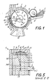
- a opening roller 2 which is equipped with a set 3, here sawtooth-shaped.
- the opening roller 2 is mounted with an axis 4 in the wall of the housing 1.
- the sliver 5 is fed to the opening roller 2 via a compressor 6 from a feed roller 7 through the feed opening 8 in the housing 1.
- the feed tray 9 is pivotable stored and is pressed with a spring, not shown here, against the feed roller 7 in order to be able to adapt to changing thicknesses of the sliver.
- the opening roller 2 combs 5 individual fibers 11 with its clothing 3 from the fiber beard 10 of the fiber sliver projecting beyond the feed trough 9.
- the combed fibers 11 are entrained by the air flow prevailing in the housing 1.
- This air flow can be, for example, the negative pressure which is present on a spinning rotor of the spinning device. While the light fibers 11 follow the air flow, the dirt 12 is discharged from the dirt discharge opening 13 in the housing 1 due to the centrifugal force acting on it. The dirt 12 falls into a device for collection or removal, not shown here and not described in detail.
- the wall of the housing 1 relative to the opening roller 2 continues in a fiber parallelization segment 15 which is equipped with parallelization elements 16 and extends to the outlet opening 17 of the fibers 11 in the fiber feed channel 18 .
- the fiber feed channel 18 leads to the spinning device, not shown here.
- the fiber parallelization segment 15 is part of the wall of the housing 1 of the resolving unit. It consists of a recess A within the wall of the housing 1.
- the recess A in the wall of the housing 1 is formed by a circular concave contour K in the circumferential direction of the inner contour I of the housing 1.
- This recess A is filled by parallelizing elements 16.
- These parallelizing elements like the clothing of the opening roller, can be sawtooth-shaped or needle-shaped.
- the tips 16 'of the parallelization elements 16 are arranged concentrically to the opening roller 2 and aligned with the inner contour I of the housing 1.
- the gap between the clothing 3 on the opening roller 2 and the tips 16 'of the paralleling elements 16 is the same size as between the clothing 3 and the inner contour I of the wall of the housing 1.
- the parallelization elements 16 can be machined out of the wall of the housing 1, for example by grinding, eroding or milling. But they can also, and this is especially the case with needles, be inserted into the housing wall.
- the parallelization elements are arranged side by side in parallel rows. They are sawtooth-shaped and their sawtooth shape is arranged in relation to the sawtooth patterns of the clothing 3 on the opening roller 2 and rotated 180 degrees.
- the recess A has a circular contour K.
- the center MK of the circular contour K lies on a perpendicular perpendicular SM, which is perpendicular to a secant S.
- the secant S runs through the two intersections of the circular contour K with the circular inner contour I of the wall of the housing 1.
- the perpendicular perpendicular SM runs through the center of the circular inner contour I of the housing 1.
- the radius RI of the inner contour I is larger than the radius RK the circular contour K.
- the combed and separated fibers 11 freed from the dirt 12 are carried into the region of the fiber parallelization segment 15 as a result of the air flow, for example due to the negative pressure on a spinning rotor in the spinning device. There they are parallelized and stretched by the parallelization elements 16. Fibers prepared in this way deliver a particularly good spinning result. Especially when fibers are curved and tend to get caught, they are stretched and separated by the paralleling elements and optimally prepared for the spinning process.
- Fig. 2 shows the position of the fiber parallelization segment 15 within the wall of the housing 1 of the resolver.
- the housing is shown in perspective, the opening roller as well as the feed trough and the feed roller are omitted.
- the fiber parallelization segment 15 extends.
- the parallelization elements 16 lie in parallel rows next to one another and their tips 16 'are aligned with the inner contour I of the housing 1.
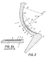
- FIG. 3 shows the longitudinal section through a fiber parallelization segment, the design of which corresponds to the exemplary embodiment in FIG. 1.
- a part of the wall of the housing 1 is shown between the dirt separation opening 13 and the outlet opening 17 for the fibers in the fiber feed channel.
- the recess A in the wall of the housing 1 has a circular contour K.
- the parallelization elements 16 are located in this recess A. They are sawtooth-shaped, the leg of the triangular shape, viewed in the direction of the fiber flight, being longer than the leg which points against the direction of the fiber flight. The inclination of the teeth is therefore exactly the opposite of the inclination of the teeth on the opening roller. This significantly increases the parallel effect of the parallel elements.
- the tips 16 'of the paralleling elements 16 are aligned with the inner contour I of the housing 1 of the resolving unit.
- the recess A extends below a secant S, which runs between the intersection points of the contour K with the inner contour I of the housing, namely between the intersection point 19 and the intersection point 20.
- the center point MK of the contour K lies on a perpendicular perpendicular SM on the secant S. This perpendicular perpendicular SM passes through the center MI of the circular inner contour I of the housing 1.
- the radius RK of the circular contour K is smaller than the radius RI of the inner contour I of the housing 1.
- the size of the parallelization elements 16 increases continuously in order to reach its greatest height in the region of the perpendicular perpendicular SM. Thereafter, the size of the parallelization elements 16 decreases continuously in order to decrease to zero again at the intersection 20 of the secant. At this point, the parallelization of the fibers is complete and they enter the outlet opening 17 of the fiber feed channel 18.
- FIG. 4 shows a further embodiment of a fiber parallelization segment 15.
- a perspective view of the housing 1 can also be seen here with the feed part broken away and the feed roller omitted.
- a fiber parallelization segment 15 extends.
- the recess A ' is formed by penetrating the wall of the housing 1 through the contour K' of a ball, the center of which MK 'on a Center perpendicular SM 'is located on a maximum secant S' and the center perpendicular MS 'goes through the center line MI of the cylindrical inner contour I of the housing 1.
- the fiber parallelization segment 15 begins with a tip and runs ever wider and deeper apart then then continuously decrease again in the circumferential direction of the inner contour I of the housing 1 after exceeding the maximum secant S '. Also in the present case, the tips of the parallelization elements 16 'are aligned with the inner contour I of the housing 1. The height of the parallelization elements 16 thus decreases continuously towards the edges of the fiber parallelization segment 15.
- FIG. 5 shows the embodiment of the fiber parallelization segment according to FIG. 4 in the section shown there.
- the opening roller 2 is inserted into the housing 1.
- the opening roller 2 with its opening set 3 is mounted with its shaft 4 in the housing 1.
- the opening roller 2 on its circumference opposite wall of the housing 1 has the recess A ', which was described in the embodiment of FIG. 4.
- the recess A ' cuts a segment of a circle from the wall of the housing 1. It is limited by the inner contour I of the housing 1 and cuts these in points 21 and 22.
- the secant S' coincides here with the inner contour I of the housing on average.
- On the perpendicular perpendicular SM 'of the secant S' is the center MK 'of the contour K'.
- the perpendicular perpendicular SM ' is at the same time radius RI of the inner contour of the housing. This radius RI is larger than the radius RK 'of the contour K' of the recess A '.
- the set 3 of the opening roller 2 are opposite the parallelization elements 16. Their tips 16 'are aligned with the inner contour I of the housing 1.
- the parallelizing elements are largest in the region of the recess A', which is opposite the central circumference of the opening roller 2. Most of the fibers are usually located in this area, so that the desired parallelization effect occurs more intensely there.
- the fiber parallelization segment In the area of the highest amount of fibers, in the area of the center line of the opening roller, the fiber parallelization segment has its greatest extent in the circumferential direction on the inner contour of the housing seen.
- spheres, ellipsoids, paraboloids or hyperboloids can be used as rotational bodies.
- the tools for producing the desired contours are shaped like the rotationally symmetrical bodies when the paralleling elements are eroded out of the wall, ground out or milled out.
- needles in the recess are aligned concentrically with the center line of the housing contour.
- a fiber parallelization segment can also be arranged between the feed opening 8 and the dirt separation opening 13.
Landscapes
- Engineering & Computer Science (AREA)
- Mechanical Engineering (AREA)
- Textile Engineering (AREA)
- Preliminary Treatment Of Fibers (AREA)
- Spinning Or Twisting Of Yarns (AREA)
Applications Claiming Priority (2)
| Application Number | Priority Date | Filing Date | Title |
|---|---|---|---|
| DE3809717 | 1988-03-23 | ||
| DE3809717A DE3809717A1 (de) | 1988-03-23 | 1988-03-23 | Aufloeseaggregat einer offenend-spinnvorrichtung |
Publications (2)
| Publication Number | Publication Date |
|---|---|
| EP0334101A1 true EP0334101A1 (fr) | 1989-09-27 |
| EP0334101B1 EP0334101B1 (fr) | 1992-12-02 |
Family
ID=6350444
Family Applications (1)
| Application Number | Title | Priority Date | Filing Date |
|---|---|---|---|
| EP89104022A Expired - Lifetime EP0334101B1 (fr) | 1988-03-23 | 1989-03-07 | Dispositif d'ouvraison pour un métier à filer à bout libre |
Country Status (4)
| Country | Link |
|---|---|
| US (1) | US5088266A (fr) |
| EP (1) | EP0334101B1 (fr) |
| JP (1) | JPH026634A (fr) |
| DE (2) | DE3809717A1 (fr) |
Cited By (1)
| Publication number | Priority date | Publication date | Assignee | Title |
|---|---|---|---|---|
| CN113005569A (zh) * | 2021-02-20 | 2021-06-22 | 刘丽娜 | 一种纺织用棉花开棉装置 |
Families Citing this family (4)
| Publication number | Priority date | Publication date | Assignee | Title |
|---|---|---|---|---|
| DE4227885C2 (de) * | 1992-08-22 | 1994-11-17 | Rieter Ingolstadt Spinnerei | Vorrichtung zum pneumatischen Zuführen von Fasern zu der Fasersammelfläche eines Offenend-Spinnelementes |
| DE4227884C2 (de) * | 1992-08-22 | 1995-07-06 | Rieter Ingolstadt Spinnerei | Verfahren und Vorrichtung zum pneumatischen Zuführen von Fasern zu der Fasersammelfläche eines Offenend-Spinnelementes |
| CN105350116A (zh) * | 2015-11-24 | 2016-02-24 | 卓郎(金坛)纺织机械有限公司 | 一种除微尘机的定向进棉侧向排微尘结构 |
| DE102021117812A1 (de) * | 2021-07-09 | 2023-01-12 | Maschinenfabrik Rieter Ag | Auflösewalzengehäuse für eine Auflösewalze einer Offenend-Spinnvorrichtung sowie Offenend-Spinnvorrichtung mit einem Auflösewalzengehäuse |
Citations (4)
| Publication number | Priority date | Publication date | Assignee | Title |
|---|---|---|---|---|
| DE2041958A1 (de) * | 1970-08-24 | 1972-03-02 | Taschkentskoje Sp K Bjuro Text | Einrichtung zur Zufuehrung von Fasern in ein Zwirn- und Formierungsorgan einer Spinnmaschine |
| DE2606193A1 (de) * | 1975-02-28 | 1976-09-09 | Vyzk Ustav Bavlnarsky | Gehaeuse einer aufloesevorrichtung einer offen-end-rotorspinneinheit |
| DE2532993A1 (de) * | 1975-07-23 | 1977-02-10 | Hollingsworth Gmbh | Voroeffner fuer offenend-spinnmaschinen |
| DE2932562A1 (de) * | 1979-08-10 | 1981-02-12 | Hollingsworth Gmbh | Aufloesevorrichtung fuer offenend-spinnmaschine |
Family Cites Families (3)
| Publication number | Priority date | Publication date | Assignee | Title |
|---|---|---|---|---|
| US4321788A (en) * | 1978-01-20 | 1982-03-30 | Dixie Yarns, Inc. | Open end spinning apparatus |
| DE3127415A1 (de) * | 1981-07-11 | 1983-02-03 | Fritz 7347 Bad Überkingen Stahlecker | "zufuehr- und aufloeseeinrichtung fuer offenend-spinnaggregate mit einer abscheideoeffnung fuer verunreinigungen" |
| DE3402566A1 (de) * | 1984-01-26 | 1985-08-01 | Fritz 7347 Bad Überkingen Stahlecker | Vorrichtung zum oe-friktionsspinnen |
-
1988
- 1988-03-23 DE DE3809717A patent/DE3809717A1/de not_active Withdrawn
-
1989
- 1989-03-07 DE DE8989104022T patent/DE58902841D1/de not_active Expired - Fee Related
- 1989-03-07 EP EP89104022A patent/EP0334101B1/fr not_active Expired - Lifetime
- 1989-03-16 US US07/324,581 patent/US5088266A/en not_active Expired - Fee Related
- 1989-03-23 JP JP8969422A patent/JPH026634A/ja active Pending
Patent Citations (4)
| Publication number | Priority date | Publication date | Assignee | Title |
|---|---|---|---|---|
| DE2041958A1 (de) * | 1970-08-24 | 1972-03-02 | Taschkentskoje Sp K Bjuro Text | Einrichtung zur Zufuehrung von Fasern in ein Zwirn- und Formierungsorgan einer Spinnmaschine |
| DE2606193A1 (de) * | 1975-02-28 | 1976-09-09 | Vyzk Ustav Bavlnarsky | Gehaeuse einer aufloesevorrichtung einer offen-end-rotorspinneinheit |
| DE2532993A1 (de) * | 1975-07-23 | 1977-02-10 | Hollingsworth Gmbh | Voroeffner fuer offenend-spinnmaschinen |
| DE2932562A1 (de) * | 1979-08-10 | 1981-02-12 | Hollingsworth Gmbh | Aufloesevorrichtung fuer offenend-spinnmaschine |
Cited By (1)
| Publication number | Priority date | Publication date | Assignee | Title |
|---|---|---|---|---|
| CN113005569A (zh) * | 2021-02-20 | 2021-06-22 | 刘丽娜 | 一种纺织用棉花开棉装置 |
Also Published As
| Publication number | Publication date |
|---|---|
| EP0334101B1 (fr) | 1992-12-02 |
| JPH026634A (ja) | 1990-01-10 |
| DE58902841D1 (de) | 1993-01-14 |
| DE3809717A1 (de) | 1989-10-05 |
| US5088266A (en) | 1992-02-18 |
Similar Documents
| Publication | Publication Date | Title |
|---|---|---|
| DE2023234C3 (de) | Vorrichtung zum Reinigen von Fasermaterial beim Offenend-Spinnen | |
| EP0172369B1 (fr) | Procédé et dispositif pour séparer des impuretés de la matière fibreuse | |
| DE2327663A1 (de) | Vorrichtung zum auskaemmen von textilfasern beim offen-end-spinnen sowie zur entfernung ihrer verunreinigungen | |
| CH692744A5 (de) | Fadenabzugdüse. | |
| CH639436A5 (de) | Verfahren zum abscheiden von groben sowie feinen verunreinigungen aus stapelfasern und zum geraderichten dieser fasern beim offen-end-spinnen. | |
| DE2016469A1 (de) | Open-end-Spinnvorrichtung | |
| EP0334101B1 (fr) | Dispositif d'ouvraison pour un métier à filer à bout libre | |
| CH681087A5 (fr) | ||
| DE2451927A1 (de) | Einrichtung zum entfernen von schmutz in einer spinnvorrichtung | |
| DE2718146A1 (de) | Offen-end-spinnvorrichtung | |
| DE3501876C2 (fr) | ||
| DE1940271C3 (de) | Offen-End-Spinnvorrichtung | |
| CH645140A5 (de) | Aufloesevorrichtung fuer offenend-spinnmaschinen. | |
| DE3013969C2 (de) | Offenendspinneinheit | |
| DE2328611C3 (de) | Faseraufl¦sevorrichtung für eine OE-Rotorspinneinheit | |
| DE3709322C2 (de) | Zuführ- und Auflöseeinrichtung einer Offenend-Spinnvorrichtung | |
| DE3347956C2 (de) | Vorrichtung zum Abscheiden von Verunreinigungen an Offenendspinneinheiten | |
| DE4326205C1 (de) | Rundkamm | |
| DE2347327A1 (de) | Vorrichtung zum aufloesen von fasern beim offen-end-spinnprozess | |
| DE2455530A1 (de) | Verfahren zur beseitigung von verunreinigungen aus dem in der aufloesevorrichtung einer offen-end-spinneinheit aufgeloesten faserband und einrichtung zum durchfuehren dieses verfahrens | |
| DE3005821C2 (de) | Vorrichtung zum Abschneiden von Verunreinigungen in einer Rotorspinneinheit | |
| DE2448953C2 (de) | Offenendspinneinheit mit einem Spinnrotor | |
| DE3341279C2 (de) | Auflöseeinrichtung für eine OE-Rotor-Spinneinheit | |
| DE2710487A1 (de) | Vorrichtung zur pneumatischen herstellung von garn | |
| DE3221385A1 (de) | Verfahren und vorrichtung zum herstellen eines gereinigten faserstromes |
Legal Events
| Date | Code | Title | Description |
|---|---|---|---|
| PUAI | Public reference made under article 153(3) epc to a published international application that has entered the european phase |
Free format text: ORIGINAL CODE: 0009012 |
|
| AK | Designated contracting states |
Kind code of ref document: A1 Designated state(s): CH DE FR IT LI |
|
| 17P | Request for examination filed |
Effective date: 19900209 |
|
| 17Q | First examination report despatched |
Effective date: 19910722 |
|
| RAP1 | Party data changed (applicant data changed or rights of an application transferred) |
Owner name: W. SCHLAFHORST AG & CO. |
|
| ITF | It: translation for a ep patent filed | ||
| GRAA | (expected) grant |
Free format text: ORIGINAL CODE: 0009210 |
|
| AK | Designated contracting states |
Kind code of ref document: B1 Designated state(s): CH DE FR IT LI |
|
| PG25 | Lapsed in a contracting state [announced via postgrant information from national office to epo] |
Ref country code: FR Effective date: 19921202 |
|
| REF | Corresponds to: |
Ref document number: 58902841 Country of ref document: DE Date of ref document: 19930114 |
|
| EN | Fr: translation not filed | ||
| PLBE | No opposition filed within time limit |
Free format text: ORIGINAL CODE: 0009261 |
|
| STAA | Information on the status of an ep patent application or granted ep patent |
Free format text: STATUS: NO OPPOSITION FILED WITHIN TIME LIMIT |
|
| 26N | No opposition filed | ||
| PGFP | Annual fee paid to national office [announced via postgrant information from national office to epo] |
Ref country code: DE Payment date: 19950412 Year of fee payment: 7 |
|
| PGFP | Annual fee paid to national office [announced via postgrant information from national office to epo] |
Ref country code: CH Payment date: 19950505 Year of fee payment: 7 |
|
| PG25 | Lapsed in a contracting state [announced via postgrant information from national office to epo] |
Ref country code: LI Effective date: 19960331 Ref country code: CH Effective date: 19960331 |
|
| REG | Reference to a national code |
Ref country code: CH Ref legal event code: PL |
|
| PG25 | Lapsed in a contracting state [announced via postgrant information from national office to epo] |
Ref country code: DE Effective date: 19961203 |
|
| PG25 | Lapsed in a contracting state [announced via postgrant information from national office to epo] |
Ref country code: IT Free format text: LAPSE BECAUSE OF NON-PAYMENT OF DUE FEES Effective date: 20050307 |