EP0334099B1 - Bilderzeugungsverfahren - Google Patents
Bilderzeugungsverfahren Download PDFInfo
- Publication number
- EP0334099B1 EP0334099B1 EP89104005A EP89104005A EP0334099B1 EP 0334099 B1 EP0334099 B1 EP 0334099B1 EP 89104005 A EP89104005 A EP 89104005A EP 89104005 A EP89104005 A EP 89104005A EP 0334099 B1 EP0334099 B1 EP 0334099B1
- Authority
- EP
- European Patent Office
- Prior art keywords
- particles
- particle size
- image
- toner
- developer
- Prior art date
- Legal status (The legal status is an assumption and is not a legal conclusion. Google has not performed a legal analysis and makes no representation as to the accuracy of the status listed.)
- Expired - Lifetime
Links
- 238000000034 method Methods 0.000 title claims description 51
- 239000002245 particle Substances 0.000 claims description 420
- 229920005989 resin Polymers 0.000 claims description 136
- 239000011347 resin Substances 0.000 claims description 136
- 239000006249 magnetic particle Substances 0.000 claims description 92
- VYPSYNLAJGMNEJ-UHFFFAOYSA-N Silicium dioxide Chemical compound O=[Si]=O VYPSYNLAJGMNEJ-UHFFFAOYSA-N 0.000 claims description 70
- 238000009826 distribution Methods 0.000 claims description 57
- 239000000843 powder Substances 0.000 claims description 57
- 230000005684 electric field Effects 0.000 claims description 41
- 239000000377 silicon dioxide Substances 0.000 claims description 33
- PNEYBMLMFCGWSK-UHFFFAOYSA-N aluminium oxide Inorganic materials [O-2].[O-2].[O-2].[Al+3].[Al+3] PNEYBMLMFCGWSK-UHFFFAOYSA-N 0.000 claims description 27
- 239000000203 mixture Substances 0.000 claims description 24
- 230000002209 hydrophobic effect Effects 0.000 claims description 22
- GWEVSGVZZGPLCZ-UHFFFAOYSA-N Titan oxide Chemical compound O=[Ti]=O GWEVSGVZZGPLCZ-UHFFFAOYSA-N 0.000 claims description 19
- 229910052809 inorganic oxide Inorganic materials 0.000 claims description 18
- OGIDPMRJRNCKJF-UHFFFAOYSA-N titanium oxide Inorganic materials [Ti]=O OGIDPMRJRNCKJF-UHFFFAOYSA-N 0.000 claims description 16
- 229910000859 α-Fe Inorganic materials 0.000 claims description 15
- 230000002093 peripheral effect Effects 0.000 claims description 13
- 238000005054 agglomeration Methods 0.000 claims description 6
- 230000002776 aggregation Effects 0.000 claims description 6
- 238000010521 absorption reaction Methods 0.000 claims description 5
- 230000005415 magnetization Effects 0.000 claims description 2
- 229920001577 copolymer Polymers 0.000 description 27
- 238000011161 development Methods 0.000 description 26
- 238000005259 measurement Methods 0.000 description 23
- OKKJLVBELUTLKV-UHFFFAOYSA-N Methanol Chemical compound OC OKKJLVBELUTLKV-UHFFFAOYSA-N 0.000 description 15
- 239000010410 layer Substances 0.000 description 15
- 239000003795 chemical substances by application Substances 0.000 description 14
- FFUAGWLWBBFQJT-UHFFFAOYSA-N hexamethyldisilazane Chemical compound C[Si](C)(C)N[Si](C)(C)C FFUAGWLWBBFQJT-UHFFFAOYSA-N 0.000 description 14
- 230000007423 decrease Effects 0.000 description 13
- 239000000463 material Substances 0.000 description 13
- 239000000049 pigment Substances 0.000 description 13
- PPBRXRYQALVLMV-UHFFFAOYSA-N Styrene Chemical compound C=CC1=CC=CC=C1 PPBRXRYQALVLMV-UHFFFAOYSA-N 0.000 description 12
- 230000008859 change Effects 0.000 description 12
- 230000001965 increasing effect Effects 0.000 description 12
- 239000011230 binding agent Substances 0.000 description 11
- 230000000694 effects Effects 0.000 description 11
- 238000011835 investigation Methods 0.000 description 11
- 230000015572 biosynthetic process Effects 0.000 description 10
- 230000007613 environmental effect Effects 0.000 description 10
- 239000003086 colorant Substances 0.000 description 9
- 230000000052 comparative effect Effects 0.000 description 9
- 230000003247 decreasing effect Effects 0.000 description 9
- -1 polytetrafluoroethylene, monochlorotrifluoroethylene Polymers 0.000 description 9
- 238000012360 testing method Methods 0.000 description 8
- 238000012546 transfer Methods 0.000 description 7
- 239000000654 additive Substances 0.000 description 6
- 239000011248 coating agent Substances 0.000 description 6
- 238000000576 coating method Methods 0.000 description 6
- 230000008021 deposition Effects 0.000 description 6
- 230000006870 function Effects 0.000 description 6
- 239000004615 ingredient Substances 0.000 description 6
- IEQIEDJGQAUEQZ-UHFFFAOYSA-N phthalocyanine Chemical compound N1C(N=C2C3=CC=CC=C3C(N=C3C4=CC=CC=C4C(=N4)N3)=N2)=C(C=CC=C2)C2=C1N=C1C2=CC=CC=C2C4=N1 IEQIEDJGQAUEQZ-UHFFFAOYSA-N 0.000 description 6
- 230000002265 prevention Effects 0.000 description 6
- 230000001105 regulatory effect Effects 0.000 description 6
- 238000007792 addition Methods 0.000 description 5
- 230000000996 additive effect Effects 0.000 description 5
- LIKFHECYJZWXFJ-UHFFFAOYSA-N dimethyldichlorosilane Chemical compound C[Si](C)(Cl)Cl LIKFHECYJZWXFJ-UHFFFAOYSA-N 0.000 description 5
- 150000002484 inorganic compounds Chemical class 0.000 description 5
- 229910010272 inorganic material Inorganic materials 0.000 description 5
- 230000000670 limiting effect Effects 0.000 description 5
- 238000002156 mixing Methods 0.000 description 5
- 229920001225 polyester resin Polymers 0.000 description 5
- 239000004645 polyester resin Substances 0.000 description 5
- 239000002904 solvent Substances 0.000 description 5
- FAPWRFPIFSIZLT-UHFFFAOYSA-M Sodium chloride Chemical compound [Na+].[Cl-] FAPWRFPIFSIZLT-UHFFFAOYSA-M 0.000 description 4
- XLOMVQKBTHCTTD-UHFFFAOYSA-N Zinc monoxide Chemical compound [Zn]=O XLOMVQKBTHCTTD-UHFFFAOYSA-N 0.000 description 4
- 238000001816 cooling Methods 0.000 description 4
- 230000007547 defect Effects 0.000 description 4
- 239000006185 dispersion Substances 0.000 description 4
- 239000008151 electrolyte solution Substances 0.000 description 4
- 230000002708 enhancing effect Effects 0.000 description 4
- 238000002474 experimental method Methods 0.000 description 4
- 239000007788 liquid Substances 0.000 description 4
- 239000011572 manganese Substances 0.000 description 4
- 229910052751 metal Inorganic materials 0.000 description 4
- 239000002184 metal Substances 0.000 description 4
- 239000000178 monomer Substances 0.000 description 4
- 230000002829 reductive effect Effects 0.000 description 4
- XEEYBQQBJWHFJM-UHFFFAOYSA-N Iron Chemical compound [Fe] XEEYBQQBJWHFJM-UHFFFAOYSA-N 0.000 description 3
- 229910052782 aluminium Inorganic materials 0.000 description 3
- XAGFODPZIPBFFR-UHFFFAOYSA-N aluminium Chemical compound [Al] XAGFODPZIPBFFR-UHFFFAOYSA-N 0.000 description 3
- 238000004140 cleaning Methods 0.000 description 3
- 229920006026 co-polymeric resin Polymers 0.000 description 3
- 150000001875 compounds Chemical class 0.000 description 3
- 238000007334 copolymerization reaction Methods 0.000 description 3
- XCJYREBRNVKWGJ-UHFFFAOYSA-N copper(II) phthalocyanine Chemical compound [Cu+2].C12=CC=CC=C2C(N=C2[N-]C(C3=CC=CC=C32)=N2)=NC1=NC([C]1C=CC=CC1=1)=NC=1N=C1[C]3C=CC=CC3=C2[N-]1 XCJYREBRNVKWGJ-UHFFFAOYSA-N 0.000 description 3
- 230000005484 gravity Effects 0.000 description 3
- 230000008569 process Effects 0.000 description 3
- 238000002310 reflectometry Methods 0.000 description 3
- 150000003839 salts Chemical class 0.000 description 3
- 238000007789 sealing Methods 0.000 description 3
- 239000007787 solid Substances 0.000 description 3
- 241000894007 species Species 0.000 description 3
- 239000012808 vapor phase Substances 0.000 description 3
- FEIQOMCWGDNMHM-UHFFFAOYSA-N 5-phenylpenta-2,4-dienoic acid Chemical compound OC(=O)C=CC=CC1=CC=CC=C1 FEIQOMCWGDNMHM-UHFFFAOYSA-N 0.000 description 2
- 239000004925 Acrylic resin Substances 0.000 description 2
- 229920000178 Acrylic resin Polymers 0.000 description 2
- 229910002012 Aerosil® Inorganic materials 0.000 description 2
- VYZAMTAEIAYCRO-UHFFFAOYSA-N Chromium Chemical compound [Cr] VYZAMTAEIAYCRO-UHFFFAOYSA-N 0.000 description 2
- 229940126062 Compound A Drugs 0.000 description 2
- VZCYOOQTPOCHFL-OWOJBTEDSA-N Fumaric acid Chemical compound OC(=O)\C=C\C(O)=O VZCYOOQTPOCHFL-OWOJBTEDSA-N 0.000 description 2
- NLDMNSXOCDLTTB-UHFFFAOYSA-N Heterophylliin A Natural products O1C2COC(=O)C3=CC(O)=C(O)C(O)=C3C3=C(O)C(O)=C(O)C=C3C(=O)OC2C(OC(=O)C=2C=C(O)C(O)=C(O)C=2)C(O)C1OC(=O)C1=CC(O)=C(O)C(O)=C1 NLDMNSXOCDLTTB-UHFFFAOYSA-N 0.000 description 2
- PXHVJJICTQNCMI-UHFFFAOYSA-N Nickel Chemical compound [Ni] PXHVJJICTQNCMI-UHFFFAOYSA-N 0.000 description 2
- 239000002033 PVDF binder Substances 0.000 description 2
- 239000004698 Polyethylene Substances 0.000 description 2
- XOLBLPGZBRYERU-UHFFFAOYSA-N SnO2 Inorganic materials O=[Sn]=O XOLBLPGZBRYERU-UHFFFAOYSA-N 0.000 description 2
- KKEYFWRCBNTPAC-UHFFFAOYSA-N Terephthalic acid Chemical compound OC(=O)C1=CC=C(C(O)=O)C=C1 KKEYFWRCBNTPAC-UHFFFAOYSA-N 0.000 description 2
- HCHKCACWOHOZIP-UHFFFAOYSA-N Zinc Chemical compound [Zn] HCHKCACWOHOZIP-UHFFFAOYSA-N 0.000 description 2
- 239000002253 acid Substances 0.000 description 2
- 125000005396 acrylic acid ester group Chemical group 0.000 description 2
- MWPLVEDNUUSJAV-UHFFFAOYSA-N anthracene Chemical compound C1=CC=CC2=CC3=CC=CC=C3C=C21 MWPLVEDNUUSJAV-UHFFFAOYSA-N 0.000 description 2
- 239000007864 aqueous solution Substances 0.000 description 2
- 238000005452 bending Methods 0.000 description 2
- 230000008901 benefit Effects 0.000 description 2
- 230000033228 biological regulation Effects 0.000 description 2
- 229910052980 cadmium sulfide Inorganic materials 0.000 description 2
- IJOOHPMOJXWVHK-UHFFFAOYSA-N chlorotrimethylsilane Chemical compound C[Si](C)(C)Cl IJOOHPMOJXWVHK-UHFFFAOYSA-N 0.000 description 2
- 229910052804 chromium Inorganic materials 0.000 description 2
- 239000011651 chromium Substances 0.000 description 2
- 239000011362 coarse particle Substances 0.000 description 2
- 235000019646 color tone Nutrition 0.000 description 2
- 230000001276 controlling effect Effects 0.000 description 2
- 235000014113 dietary fatty acids Nutrition 0.000 description 2
- 239000002270 dispersing agent Substances 0.000 description 2
- 239000000194 fatty acid Substances 0.000 description 2
- 229930195729 fatty acid Natural products 0.000 description 2
- 150000004665 fatty acids Chemical class 0.000 description 2
- 238000010438 heat treatment Methods 0.000 description 2
- 238000004898 kneading Methods 0.000 description 2
- 239000000696 magnetic material Substances 0.000 description 2
- 238000004519 manufacturing process Methods 0.000 description 2
- 238000002844 melting Methods 0.000 description 2
- 230000008018 melting Effects 0.000 description 2
- 125000005397 methacrylic acid ester group Chemical group 0.000 description 2
- 230000004048 modification Effects 0.000 description 2
- 238000012986 modification Methods 0.000 description 2
- 150000003961 organosilicon compounds Chemical class 0.000 description 2
- 230000003647 oxidation Effects 0.000 description 2
- 238000007254 oxidation reaction Methods 0.000 description 2
- XNGIFLGASWRNHJ-UHFFFAOYSA-N phthalic acid Chemical compound OC(=O)C1=CC=CC=C1C(O)=O XNGIFLGASWRNHJ-UHFFFAOYSA-N 0.000 description 2
- 230000000704 physical effect Effects 0.000 description 2
- 229940104573 pigment red 5 Drugs 0.000 description 2
- 229920000573 polyethylene Polymers 0.000 description 2
- 229920002981 polyvinylidene fluoride Polymers 0.000 description 2
- CYIDZMCFTVVTJO-UHFFFAOYSA-N pyromellitic acid Chemical compound OC(=O)C1=CC(C(O)=O)=C(C(O)=O)C=C1C(O)=O CYIDZMCFTVVTJO-UHFFFAOYSA-N 0.000 description 2
- 230000004044 response Effects 0.000 description 2
- 230000002441 reversible effect Effects 0.000 description 2
- YGSDEFSMJLZEOE-UHFFFAOYSA-N salicylic acid Chemical class OC(=O)C1=CC=CC=C1O YGSDEFSMJLZEOE-UHFFFAOYSA-N 0.000 description 2
- 239000011669 selenium Substances 0.000 description 2
- 229910052710 silicon Inorganic materials 0.000 description 2
- 239000010703 silicon Substances 0.000 description 2
- HBMJWWWQQXIZIP-UHFFFAOYSA-N silicon carbide Chemical compound [Si+]#[C-] HBMJWWWQQXIZIP-UHFFFAOYSA-N 0.000 description 2
- 229910010271 silicon carbide Inorganic materials 0.000 description 2
- 229920002050 silicone resin Polymers 0.000 description 2
- 239000011780 sodium chloride Substances 0.000 description 2
- 239000010935 stainless steel Substances 0.000 description 2
- 229910001220 stainless steel Inorganic materials 0.000 description 2
- 229920001909 styrene-acrylic polymer Polymers 0.000 description 2
- 239000004094 surface-active agent Substances 0.000 description 2
- 238000004448 titration Methods 0.000 description 2
- VZCYOOQTPOCHFL-UHFFFAOYSA-N trans-butenedioic acid Natural products OC(=O)C=CC(O)=O VZCYOOQTPOCHFL-UHFFFAOYSA-N 0.000 description 2
- ARCGXLSVLAOJQL-UHFFFAOYSA-N trimellitic acid Chemical compound OC(=O)C1=CC=C(C(O)=O)C(C(O)=O)=C1 ARCGXLSVLAOJQL-UHFFFAOYSA-N 0.000 description 2
- XLYOFNOQVPJJNP-UHFFFAOYSA-N water Substances O XLYOFNOQVPJJNP-UHFFFAOYSA-N 0.000 description 2
- 239000011701 zinc Substances 0.000 description 2
- 229910052725 zinc Inorganic materials 0.000 description 2
- 239000011787 zinc oxide Substances 0.000 description 2
- YTLYLLTVENPWFT-UPHRSURJSA-N (Z)-3-aminoacrylic acid Chemical compound N\C=C/C(O)=O YTLYLLTVENPWFT-UPHRSURJSA-N 0.000 description 1
- YQJPWWLJDNCSCN-UHFFFAOYSA-N 1,3-diphenyltetramethyldisiloxane Chemical compound C=1C=CC=CC=1[Si](C)(C)O[Si](C)(C)C1=CC=CC=C1 YQJPWWLJDNCSCN-UHFFFAOYSA-N 0.000 description 1
- OSNILPMOSNGHLC-UHFFFAOYSA-N 1-[4-methoxy-3-(piperidin-1-ylmethyl)phenyl]ethanone Chemical compound COC1=CC=C(C(C)=O)C=C1CN1CCCCC1 OSNILPMOSNGHLC-UHFFFAOYSA-N 0.000 description 1
- KTZVZZJJVJQZHV-UHFFFAOYSA-N 1-chloro-4-ethenylbenzene Chemical compound ClC1=CC=C(C=C)C=C1 KTZVZZJJVJQZHV-UHFFFAOYSA-N 0.000 description 1
- ABPSJVSWZJJPOQ-UHFFFAOYSA-N 3,4-ditert-butyl-2-hydroxybenzoic acid Chemical compound CC(C)(C)C1=CC=C(C(O)=O)C(O)=C1C(C)(C)C ABPSJVSWZJJPOQ-UHFFFAOYSA-N 0.000 description 1
- WUPHOULIZUERAE-UHFFFAOYSA-N 3-(oxolan-2-yl)propanoic acid Chemical compound OC(=O)CCC1CCCO1 WUPHOULIZUERAE-UHFFFAOYSA-N 0.000 description 1
- RSWGJHLUYNHPMX-UHFFFAOYSA-N Abietic-Saeure Natural products C12CCC(C(C)C)=CC2=CCC2C1(C)CCCC2(C)C(O)=O RSWGJHLUYNHPMX-UHFFFAOYSA-N 0.000 description 1
- RYGMFSIKBFXOCR-UHFFFAOYSA-N Copper Chemical compound [Cu] RYGMFSIKBFXOCR-UHFFFAOYSA-N 0.000 description 1
- VGGSQFUCUMXWEO-UHFFFAOYSA-N Ethene Chemical compound C=C VGGSQFUCUMXWEO-UHFFFAOYSA-N 0.000 description 1
- 239000005977 Ethylene Substances 0.000 description 1
- 229910000640 Fe alloy Inorganic materials 0.000 description 1
- YCKRFDGAMUMZLT-UHFFFAOYSA-N Fluorine atom Chemical compound [F] YCKRFDGAMUMZLT-UHFFFAOYSA-N 0.000 description 1
- 229910005987 Ge3N4 Inorganic materials 0.000 description 1
- 239000013032 Hydrocarbon resin Substances 0.000 description 1
- 239000004952 Polyamide Substances 0.000 description 1
- 239000004793 Polystyrene Substances 0.000 description 1
- OFOBLEOULBTSOW-UHFFFAOYSA-N Propanedioic acid Natural products OC(=O)CC(O)=O OFOBLEOULBTSOW-UHFFFAOYSA-N 0.000 description 1
- KHPCPRHQVVSZAH-HUOMCSJISA-N Rosin Natural products O(C/C=C/c1ccccc1)[C@H]1[C@H](O)[C@@H](O)[C@@H](O)[C@@H](CO)O1 KHPCPRHQVVSZAH-HUOMCSJISA-N 0.000 description 1
- BUGBHKTXTAQXES-UHFFFAOYSA-N Selenium Chemical compound [Se] BUGBHKTXTAQXES-UHFFFAOYSA-N 0.000 description 1
- 229910052581 Si3N4 Inorganic materials 0.000 description 1
- 229920002125 Sokalan® Polymers 0.000 description 1
- 229920007962 Styrene Methyl Methacrylate Polymers 0.000 description 1
- RTAQQCXQSZGOHL-UHFFFAOYSA-N Titanium Chemical compound [Ti] RTAQQCXQSZGOHL-UHFFFAOYSA-N 0.000 description 1
- 238000005411 Van der Waals force Methods 0.000 description 1
- KTVHXOHGRUQTPX-UHFFFAOYSA-N [ethenyl(dimethyl)silyl] acetate Chemical compound CC(=O)O[Si](C)(C)C=C KTVHXOHGRUQTPX-UHFFFAOYSA-N 0.000 description 1
- 238000005299 abrasion Methods 0.000 description 1
- 239000003082 abrasive agent Substances 0.000 description 1
- 230000009471 action Effects 0.000 description 1
- 125000002723 alicyclic group Chemical group 0.000 description 1
- 125000001931 aliphatic group Chemical group 0.000 description 1
- 125000005907 alkyl ester group Chemical group 0.000 description 1
- 229910045601 alloy Inorganic materials 0.000 description 1
- 239000000956 alloy Substances 0.000 description 1
- CEGOLXSVJUTHNZ-UHFFFAOYSA-K aluminium tristearate Chemical compound [Al+3].CCCCCCCCCCCCCCCCCC([O-])=O.CCCCCCCCCCCCCCCCCC([O-])=O.CCCCCCCCCCCCCCCCCC([O-])=O CEGOLXSVJUTHNZ-UHFFFAOYSA-K 0.000 description 1
- 229940063655 aluminum stearate Drugs 0.000 description 1
- 229910021417 amorphous silicon Inorganic materials 0.000 description 1
- 150000008064 anhydrides Chemical class 0.000 description 1
- QFFVPLLCYGOFPU-UHFFFAOYSA-N barium chromate Chemical compound [Ba+2].[O-][Cr]([O-])(=O)=O QFFVPLLCYGOFPU-UHFFFAOYSA-N 0.000 description 1
- ABHNFDUSOVXXOA-UHFFFAOYSA-N benzyl-chloro-dimethylsilane Chemical compound C[Si](C)(Cl)CC1=CC=CC=C1 ABHNFDUSOVXXOA-UHFFFAOYSA-N 0.000 description 1
- 238000005513 bias potential Methods 0.000 description 1
- IISBACLAFKSPIT-UHFFFAOYSA-N bisphenol A Chemical class C=1C=C(O)C=CC=1C(C)(C)C1=CC=C(O)C=C1 IISBACLAFKSPIT-UHFFFAOYSA-N 0.000 description 1
- CAURZYXCQQWBJO-UHFFFAOYSA-N bromomethyl-chloro-dimethylsilane Chemical compound C[Si](C)(Cl)CBr CAURZYXCQQWBJO-UHFFFAOYSA-N 0.000 description 1
- 230000001680 brushing effect Effects 0.000 description 1
- QHIWVLPBUQWDMQ-UHFFFAOYSA-N butyl prop-2-enoate;methyl 2-methylprop-2-enoate;prop-2-enoic acid Chemical compound OC(=O)C=C.COC(=O)C(C)=C.CCCCOC(=O)C=C QHIWVLPBUQWDMQ-UHFFFAOYSA-N 0.000 description 1
- 239000003990 capacitor Substances 0.000 description 1
- 239000006229 carbon black Substances 0.000 description 1
- 150000001732 carboxylic acid derivatives Chemical class 0.000 description 1
- 229910000420 cerium oxide Inorganic materials 0.000 description 1
- 239000003153 chemical reaction reagent Substances 0.000 description 1
- ITKVLPYNJQOCPW-UHFFFAOYSA-N chloro-(chloromethyl)-dimethylsilane Chemical compound C[Si](C)(Cl)CCl ITKVLPYNJQOCPW-UHFFFAOYSA-N 0.000 description 1
- KMVZWUQHMJAWSY-UHFFFAOYSA-N chloro-dimethyl-prop-2-enylsilane Chemical compound C[Si](C)(Cl)CC=C KMVZWUQHMJAWSY-UHFFFAOYSA-N 0.000 description 1
- 230000001112 coagulating effect Effects 0.000 description 1
- 239000011247 coating layer Substances 0.000 description 1
- 229910017052 cobalt Inorganic materials 0.000 description 1
- 239000010941 cobalt Substances 0.000 description 1
- GUTLYIVDDKVIGB-UHFFFAOYSA-N cobalt atom Chemical compound [Co] GUTLYIVDDKVIGB-UHFFFAOYSA-N 0.000 description 1
- 238000004737 colorimetric analysis Methods 0.000 description 1
- 150000004696 coordination complex Chemical class 0.000 description 1
- 229910052802 copper Inorganic materials 0.000 description 1
- 239000010949 copper Substances 0.000 description 1
- 230000006866 deterioration Effects 0.000 description 1
- IGFFTOVGRACDBL-UHFFFAOYSA-N dichloro-phenyl-prop-2-enylsilane Chemical compound C=CC[Si](Cl)(Cl)C1=CC=CC=C1 IGFFTOVGRACDBL-UHFFFAOYSA-N 0.000 description 1
- ZZNQQQWFKKTOSD-UHFFFAOYSA-N diethoxy(diphenyl)silane Chemical compound C=1C=CC=CC=1[Si](OCC)(OCC)C1=CC=CC=C1 ZZNQQQWFKKTOSD-UHFFFAOYSA-N 0.000 description 1
- JJQZDUKDJDQPMQ-UHFFFAOYSA-N dimethoxy(dimethyl)silane Chemical compound CO[Si](C)(C)OC JJQZDUKDJDQPMQ-UHFFFAOYSA-N 0.000 description 1
- 235000013870 dimethyl polysiloxane Nutrition 0.000 description 1
- 150000002009 diols Chemical class 0.000 description 1
- 238000007598 dipping method Methods 0.000 description 1
- 238000001035 drying Methods 0.000 description 1
- 210000005069 ears Anatomy 0.000 description 1
- 239000003822 epoxy resin Substances 0.000 description 1
- BITPLIXHRASDQB-UHFFFAOYSA-N ethenyl-[ethenyl(dimethyl)silyl]oxy-dimethylsilane Chemical compound C=C[Si](C)(C)O[Si](C)(C)C=C BITPLIXHRASDQB-UHFFFAOYSA-N 0.000 description 1
- DRUOQOFQRYFQGB-UHFFFAOYSA-N ethoxy(dimethyl)silicon Chemical compound CCO[Si](C)C DRUOQOFQRYFQGB-UHFFFAOYSA-N 0.000 description 1
- RSIHJDGMBDPTIM-UHFFFAOYSA-N ethoxy(trimethyl)silane Chemical compound CCO[Si](C)(C)C RSIHJDGMBDPTIM-UHFFFAOYSA-N 0.000 description 1
- 239000005038 ethylene vinyl acetate Substances 0.000 description 1
- 229920006226 ethylene-acrylic acid Polymers 0.000 description 1
- 238000011156 evaluation Methods 0.000 description 1
- 239000010419 fine particle Substances 0.000 description 1
- 238000007667 floating Methods 0.000 description 1
- 239000011737 fluorine Substances 0.000 description 1
- 229910052731 fluorine Inorganic materials 0.000 description 1
- 230000004907 flux Effects 0.000 description 1
- 239000001530 fumaric acid Substances 0.000 description 1
- LNEPOXFFQSENCJ-UHFFFAOYSA-N haloperidol Chemical compound C1CC(O)(C=2C=CC(Cl)=CC=2)CCN1CCCC(=O)C1=CC=C(F)C=C1 LNEPOXFFQSENCJ-UHFFFAOYSA-N 0.000 description 1
- UQEAIHBTYFGYIE-UHFFFAOYSA-N hexamethyldisiloxane Chemical compound C[Si](C)(C)O[Si](C)(C)C UQEAIHBTYFGYIE-UHFFFAOYSA-N 0.000 description 1
- 229920001519 homopolymer Polymers 0.000 description 1
- 229920006270 hydrocarbon resin Polymers 0.000 description 1
- 125000002887 hydroxy group Chemical group [H]O* 0.000 description 1
- 230000001771 impaired effect Effects 0.000 description 1
- 230000006872 improvement Effects 0.000 description 1
- UHOKSCJSTAHBSO-UHFFFAOYSA-N indanthrone blue Chemical compound C1=CC=C2C(=O)C3=CC=C4NC5=C6C(=O)C7=CC=CC=C7C(=O)C6=CC=C5NC4=C3C(=O)C2=C1 UHOKSCJSTAHBSO-UHFFFAOYSA-N 0.000 description 1
- 239000011810 insulating material Substances 0.000 description 1
- 229910052742 iron Inorganic materials 0.000 description 1
- 239000000314 lubricant Substances 0.000 description 1
- VZCYOOQTPOCHFL-UPHRSURJSA-N maleic acid Chemical compound OC(=O)\C=C/C(O)=O VZCYOOQTPOCHFL-UPHRSURJSA-N 0.000 description 1
- 239000011976 maleic acid Substances 0.000 description 1
- FPYJFEHAWHCUMM-UHFFFAOYSA-N maleic anhydride Chemical compound O=C1OC(=O)C=C1 FPYJFEHAWHCUMM-UHFFFAOYSA-N 0.000 description 1
- WPBNNNQJVZRUHP-UHFFFAOYSA-L manganese(2+);methyl n-[[2-(methoxycarbonylcarbamothioylamino)phenyl]carbamothioyl]carbamate;n-[2-(sulfidocarbothioylamino)ethyl]carbamodithioate Chemical compound [Mn+2].[S-]C(=S)NCCNC([S-])=S.COC(=O)NC(=S)NC1=CC=CC=C1NC(=S)NC(=O)OC WPBNNNQJVZRUHP-UHFFFAOYSA-L 0.000 description 1
- 150000001247 metal acetylides Chemical class 0.000 description 1
- 229910044991 metal oxide Inorganic materials 0.000 description 1
- 150000004706 metal oxides Chemical class 0.000 description 1
- ADFPJHOAARPYLP-UHFFFAOYSA-N methyl 2-methylprop-2-enoate;styrene Chemical compound COC(=O)C(C)=C.C=CC1=CC=CC=C1 ADFPJHOAARPYLP-UHFFFAOYSA-N 0.000 description 1
- 239000005055 methyl trichlorosilane Substances 0.000 description 1
- JLUFWMXJHAVVNN-UHFFFAOYSA-N methyltrichlorosilane Chemical compound C[Si](Cl)(Cl)Cl JLUFWMXJHAVVNN-UHFFFAOYSA-N 0.000 description 1
- 229910052759 nickel Inorganic materials 0.000 description 1
- 150000004767 nitrides Chemical class 0.000 description 1
- 230000003287 optical effect Effects 0.000 description 1
- BMMGVYCKOGBVEV-UHFFFAOYSA-N oxo(oxoceriooxy)cerium Chemical compound [Ce]=O.O=[Ce]=O BMMGVYCKOGBVEV-UHFFFAOYSA-N 0.000 description 1
- SOQBVABWOPYFQZ-UHFFFAOYSA-N oxygen(2-);titanium(4+) Chemical group [O-2].[O-2].[Ti+4] SOQBVABWOPYFQZ-UHFFFAOYSA-N 0.000 description 1
- FJKROLUGYXJWQN-UHFFFAOYSA-N papa-hydroxy-benzoic acid Natural products OC(=O)C1=CC=C(O)C=C1 FJKROLUGYXJWQN-UHFFFAOYSA-N 0.000 description 1
- 239000012188 paraffin wax Substances 0.000 description 1
- 238000005192 partition Methods 0.000 description 1
- 239000003208 petroleum Substances 0.000 description 1
- 229920001568 phenolic resin Polymers 0.000 description 1
- 239000005011 phenolic resin Substances 0.000 description 1
- 229920003227 poly(N-vinyl carbazole) Polymers 0.000 description 1
- 229920001490 poly(butyl methacrylate) polymer Polymers 0.000 description 1
- 229920000435 poly(dimethylsiloxane) Polymers 0.000 description 1
- 229920003229 poly(methyl methacrylate) Polymers 0.000 description 1
- 229920002285 poly(styrene-co-acrylonitrile) Polymers 0.000 description 1
- 229920002037 poly(vinyl butyral) polymer Polymers 0.000 description 1
- 239000004584 polyacrylic acid Substances 0.000 description 1
- 229920002647 polyamide Polymers 0.000 description 1
- 229920006122 polyamide resin Polymers 0.000 description 1
- 238000006068 polycondensation reaction Methods 0.000 description 1
- 229920000647 polyepoxide Polymers 0.000 description 1
- 229920000728 polyester Polymers 0.000 description 1
- 229920000642 polymer Polymers 0.000 description 1
- 239000004926 polymethyl methacrylate Substances 0.000 description 1
- 229920002223 polystyrene Polymers 0.000 description 1
- 229920001343 polytetrafluoroethylene Polymers 0.000 description 1
- 239000004810 polytetrafluoroethylene Substances 0.000 description 1
- 229920002689 polyvinyl acetate Polymers 0.000 description 1
- 239000011118 polyvinyl acetate Substances 0.000 description 1
- 229920002102 polyvinyl toluene Polymers 0.000 description 1
- 239000011164 primary particle Substances 0.000 description 1
- 238000007639 printing Methods 0.000 description 1
- 125000004805 propylene group Chemical group [H]C([H])([H])C([H])([*:1])C([H])([H])[*:2] 0.000 description 1
- 229910052761 rare earth metal Inorganic materials 0.000 description 1
- 230000009467 reduction Effects 0.000 description 1
- 238000011160 research Methods 0.000 description 1
- PYWVYCXTNDRMGF-UHFFFAOYSA-N rhodamine B Chemical compound [Cl-].C=12C=CC(=[N+](CC)CC)C=C2OC2=CC(N(CC)CC)=CC=C2C=1C1=CC=CC=C1C(O)=O PYWVYCXTNDRMGF-UHFFFAOYSA-N 0.000 description 1
- 229960004889 salicylic acid Drugs 0.000 description 1
- 229910052711 selenium Inorganic materials 0.000 description 1
- 229910000077 silane Inorganic materials 0.000 description 1
- 150000003377 silicon compounds Chemical class 0.000 description 1
- 229920002545 silicone oil Polymers 0.000 description 1
- 239000000243 solution Substances 0.000 description 1
- 238000001179 sorption measurement Methods 0.000 description 1
- 125000006850 spacer group Chemical group 0.000 description 1
- 230000003068 static effect Effects 0.000 description 1
- 229920003048 styrene butadiene rubber Polymers 0.000 description 1
- 239000000126 substance Substances 0.000 description 1
- 238000006467 substitution reaction Methods 0.000 description 1
- 230000001502 supplementing effect Effects 0.000 description 1
- 239000000725 suspension Substances 0.000 description 1
- 229920005992 thermoplastic resin Polymers 0.000 description 1
- 230000008719 thickening Effects 0.000 description 1
- 229910001887 tin oxide Inorganic materials 0.000 description 1
- KHPCPRHQVVSZAH-UHFFFAOYSA-N trans-cinnamyl beta-D-glucopyranoside Natural products OC1C(O)C(O)C(CO)OC1OCC=CC1=CC=CC=C1 KHPCPRHQVVSZAH-UHFFFAOYSA-N 0.000 description 1
- FLPXNJHYVOVLSD-UHFFFAOYSA-N trichloro(2-chloroethyl)silane Chemical compound ClCC[Si](Cl)(Cl)Cl FLPXNJHYVOVLSD-UHFFFAOYSA-N 0.000 description 1
- NMEPHPOFYLLFTK-UHFFFAOYSA-N trimethoxy(octyl)silane Chemical compound CCCCCCCC[Si](OC)(OC)OC NMEPHPOFYLLFTK-UHFFFAOYSA-N 0.000 description 1
- KHOQXNHADJBILQ-UHFFFAOYSA-N trimethyl(sulfanyl)silane Chemical compound C[Si](C)(C)S KHOQXNHADJBILQ-UHFFFAOYSA-N 0.000 description 1
- 239000005051 trimethylchlorosilane Substances 0.000 description 1
- PQDJYEQOELDLCP-UHFFFAOYSA-N trimethylsilane Chemical compound C[SiH](C)C PQDJYEQOELDLCP-UHFFFAOYSA-N 0.000 description 1
- 125000000391 vinyl group Chemical group [H]C([*])=C([H])[H] 0.000 description 1
- 229920002554 vinyl polymer Polymers 0.000 description 1
- XOOUIPVCVHRTMJ-UHFFFAOYSA-L zinc stearate Chemical compound [Zn+2].CCCCCCCCCCCCCCCCCC([O-])=O.CCCCCCCCCCCCCCCCCC([O-])=O XOOUIPVCVHRTMJ-UHFFFAOYSA-L 0.000 description 1
Images


Classifications
-
- G—PHYSICS
- G03—PHOTOGRAPHY; CINEMATOGRAPHY; ANALOGOUS TECHNIQUES USING WAVES OTHER THAN OPTICAL WAVES; ELECTROGRAPHY; HOLOGRAPHY
- G03G—ELECTROGRAPHY; ELECTROPHOTOGRAPHY; MAGNETOGRAPHY
- G03G9/00—Developers
- G03G9/08—Developers with toner particles
- G03G9/0819—Developers with toner particles characterised by the dimensions of the particles
-
- G—PHYSICS
- G03—PHOTOGRAPHY; CINEMATOGRAPHY; ANALOGOUS TECHNIQUES USING WAVES OTHER THAN OPTICAL WAVES; ELECTROGRAPHY; HOLOGRAPHY
- G03G—ELECTROGRAPHY; ELECTROPHOTOGRAPHY; MAGNETOGRAPHY
- G03G13/00—Electrographic processes using a charge pattern
- G03G13/06—Developing
- G03G13/08—Developing using a solid developer, e.g. powder developer
- G03G13/09—Developing using a solid developer, e.g. powder developer using magnetic brush
-
- G—PHYSICS
- G03—PHOTOGRAPHY; CINEMATOGRAPHY; ANALOGOUS TECHNIQUES USING WAVES OTHER THAN OPTICAL WAVES; ELECTROGRAPHY; HOLOGRAPHY
- G03G—ELECTROGRAPHY; ELECTROPHOTOGRAPHY; MAGNETOGRAPHY
- G03G9/00—Developers
- G03G9/08—Developers with toner particles
- G03G9/097—Plasticisers; Charge controlling agents
- G03G9/09708—Inorganic compounds
- G03G9/09716—Inorganic compounds treated with organic compounds
-
- G—PHYSICS
- G03—PHOTOGRAPHY; CINEMATOGRAPHY; ANALOGOUS TECHNIQUES USING WAVES OTHER THAN OPTICAL WAVES; ELECTROGRAPHY; HOLOGRAPHY
- G03G—ELECTROGRAPHY; ELECTROPHOTOGRAPHY; MAGNETOGRAPHY
- G03G9/00—Developers
- G03G9/08—Developers with toner particles
- G03G9/097—Plasticisers; Charge controlling agents
- G03G9/09708—Inorganic compounds
- G03G9/09725—Silicon-oxides; Silicates
-
- G—PHYSICS
- G03—PHOTOGRAPHY; CINEMATOGRAPHY; ANALOGOUS TECHNIQUES USING WAVES OTHER THAN OPTICAL WAVES; ELECTROGRAPHY; HOLOGRAPHY
- G03G—ELECTROGRAPHY; ELECTROPHOTOGRAPHY; MAGNETOGRAPHY
- G03G9/00—Developers
- G03G9/08—Developers with toner particles
- G03G9/10—Developers with toner particles characterised by carrier particles
- G03G9/107—Developers with toner particles characterised by carrier particles having magnetic components
- G03G9/108—Ferrite carrier, e.g. magnetite
- G03G9/1085—Ferrite carrier, e.g. magnetite with non-ferrous metal oxide, e.g. MgO-Fe2O3
Definitions
- the present invention relates to an image-forming method, which is used for developing electric latent images in image forming methods such as electrophotography and electrostatic printing.
- electrostatic latent images are formed on a photoconductive layerora photosensitive plate comprising an inorganic photoconductive material such as selenium, zinc oxide and cadmium sulfide, or an organic photoconductive material such as anthracene and polyvinyl carbazole, dispersed in a binder resin as desired, subsequently developed by use of a developer comprising a toner to form a toner image, and the toner image is optionally transferred onto a transfer material (or transfer-receiving material) such as paper, and then fixed by heating, pressurization, heating and pressurization, or with solvent vapor to obtain copied products or prints.
- a transfer material or transfer-receiving material
- the triboelectric charging characteristic between the toner and a toner-carrying member is important at the time of the development. If the charge amount of the toner is too small, the electrostatic attraction between the toner and the toner-carrying member is weak and therefore the toner particles are easily released from the toner-carrying member under a slight impact, whereby fog occurs in the resultant image. On the other hand, if the charge amount of the toner is too large, the toner particles are difficult to be released from the toner-carrying member even at the time of development, whereby not only the device used therefor is required to provide a strong electric field, but also the developability decreases to cause image density unevenness. Accordingly, in the production of a toner, it is necessary to provide a toner which is capable of controlling or regulating a charge amount in a suitable range.
- the principal object has been directed to the application of the alternating electric field in order to suitably and stably attach the toner particles to the image portion and to prevent fog in the non-image (or background) portion (i.e., to prevent the toner particles from attaching to the non-image portion).
- the developer comprises at least toner particles (comprising colored resin particles, and optionally various additions) and carrier particles
- the carrier particles perform an important function in the two-component developing system
- the loss of the carrier particles based on the above-mentioned attachment thereof to the image portion causes a problem that a charge amount cannot be stably imparted to the toner particles, in any of the non-contact-type developing method and the contact-type developing method.
- image forming apparatus such as electrophotographic copying machines have recently been used widely, their uses have also extended in various ways, and higher image quality has been demanded. For example, when original images such as photograph catalog and map are copied, it is demanded that even minute portions are reproduced extremely finely and faithfully without thickening or deformation, or interruption.
- the resultant latent picture is formed by a gathering of dot with a constant potential, and the solid, half tone and highlight portions of the picture can be expressed by varying densities of dots.
- the dots are not faithfully covered with toner particles and the toner particles protrude from the dots, there arises a problem that a gradational characteristic of a toner image corresponding to the dot density ratio of the black portion to the white portion in the digital latent image cannot be obtained.
- the reproducibility becomes poorer with respect to the latent image comprising minute dots, whereby there tends to occur an image without sharpness having a low resolution and a poor gradational characteristic (particularly, in the highlight portion).
- JP-A, KOKAI Japanese Laid-Open Patent Application
- JP-A, KOKAI Japanese Laid-Open Patent Application
- No. 3244/1976 corresponding to U.S. Patent Nos. 3942979, 3969251 and 4112024
- This toner predominantly comprises relatively coarse particles having a particle size of 8 - 12 microns.
- the above-mentioned toner has a characteristic such that it contains 30 % by number or less of particles of 5 microns or smaller and 5 % by number or less of particles of 20 microns or larger, and therefore it has a broad particle size distribution which tends to decrease the uniformity in the resultant image.
- Japanese Laid-Open Patent Application No. 72054/1979 (corresponding to U.S. patent No. 4284701) has proposed a non-magnetic toner having a sharper particle size distribution than that of the above-mentioned toner.
- particles having an intermediate weight has a relatively large particle size of 8.5 - 11.0 microns, and there is still room for improvement as a color toner for attaining a high resolution and faithfully reproducing a latent image of minute dots.
- Japanese Laid-Open Patent Application No. 129437/1983 (corresponding to British Patent No. 2114310) has proposed a non-magnetic toner wherein the average particle size is 6 - 10 microns and the mode particle size is 5 - 8 microns.
- this toner only contains particles of 5 microns or less in a small amount of 15 % by number or below, and it tends to form an image without sharpness.
- toner particles having a particle size of 5 microns or smaller have a primary function of clearly reproducing the minute dots of a latent image and of attaining close and precise cover-up of the toner to the entire latent image portion.
- the field intensity in the edge portion of the minute dots is higher than that in the inner portion thereof because of the concentration of the electric lines of force, whereby the sharpness of the resultant image is determined by the quality of toner particles collected to this portion.
- the control of quantity and distribution state for toner particles of 5 microns or smaller is effective in solving the problem in the gradational characteristic in a highlight portion.
- toner particles As the particle size of toner particles is decreased to increase the amount of those having a particle size of 5 microns or smaller, the agglomerative property of the toner particles becomes stronger thereby to cause a problem such that their mixability with carrier particles decreases or their fluidity decreases.
- an image forming method including forming a layer of electrically charged toner particles on a surface of the developer carrying member and dispersing magnetic particles retaining upon their surfaces electrically charged toner particles on the surface of the developer carrying member, carrying the particles on the developer carrying member to a developing position where a surface of an electrostatic latent image bearing member for bearing an electrostatic latent image is opposed with a clearance to the surface of the developer carrying member, applying an alternating electric field across the clearance and forming the magnetic particles into chains of the particles by a magnetic field generating means disposed behind the developer carrying member and developing the electrostatic latent image by the charged toner particles on the surface of the developer carrying member and on the surfaces of the magnetic particles, and providing a developer comprising colored resin particles having a particle size in the range of 7 to 20 f..lm, silica particles to enhence the flowability and magnetic particles, wherein the frequency ⁇ (KHz) of the alternating electric field may be 0.2 to 3, the relative volumetric ratio Q (%)
- it is an object of the present invention is to provide such a method using a developer which has a stable triboelectric chargeability, and particularly is excellent in prevention of the attachment of magnetic (or carrier) particles.
- Another object of the present invention is to provide an image forming method using a color developer which is excellent in color mixing characteristic and particularly in light-transmissivity when used for an overhead projector (OHP) transparency.
- a further object of the present invention is to provide an image forming method using a color developer which provides little scattering of toner particles.
- a further object of the present invention is to provide an image forming method using a developer capable of providing high-quality images having good color-reproducibility.
- a further object of the present invention is to provide an image forming method using a developer which shows little change in performances even when environmental conditions change.
- a further object of the present invention is to provide an image forming method using a developer capable of retaining good developing characteristics under low temperature-low humidity conditions and retaining suitable developing characteristics under high temperature-high humidity conditions.
- a further object of the present invention is to provide an image forming method using a toner and a developer having excellent fluidity.
- a further object of the present invention is to provide an image forming method using a color toner which has an excellent thin-line reproducibility and gradational characteristic in a highlight portion and is capable of providing a high image density.
- a further object of the present invention is to provide an image forming method using a color toner which shows little change in performances when used in a long period.
- a further object of the present invention is to provide an image forming method using a color toner which shows little change in performances even when environmental conditions change.
- a further object of the present invention is to provide an image forming method using a color toner which shows an excellent transferability.
- a further object of the present invention is to provide an image forming method using a color toner which is capable of providing a high image density by using a small consumption thereof.
- a still further object of the present invention is to provide an image forming method using a color toner which is capable of forming a toner image excellent in resolution, gradational characteristic in a highlight portion, and thin-line reproducibility even when used in an image forming apparatus using a digital image signal.
- an image forming method comprising:
- the developer used according to the present invention comprises, at least, magnetic particles, colored resinous particles and a fluidity improver.
- magnetic particles at least, magnetic particles, colored resinous particles and a fluidity improver.
- the magnetic particles (carrier) used in the present invention may be composed of, e.g., iron or an alloy of iron with nickel, copper, zinc, cobalt, manganese, chromium, and rare earth elements in the surface oxidized form or in the surface non-oxidized form, or of an oxide or ferrite form of these metal or alloys.
- the surface of the magnetic particles with a resin.
- the magnetic particles may preferably be coated with a resin by dipping the carrier in a solution or suspension of a coating material of a resin in view of the stability of the resultant coating layer.
- the coating material on the magnetic particle surface may vary depending on the material for the colored resin particle or toner.
- Preferred examples of the resin used for positively charging the colored resin particle or toner particle may for example include aminoacrylate resins, acrylic resins, or copolymer resins comprising a styrene-type monomer and a monomer constituting the above-mentioned resins, because these resins are on the positive side in the electrification series.
- preferred examples of the resin used for negatively charging the colored resin particle or toner particle may include: silicone resins, polyester resins, polytetrafluoroethylene, monochlorotrifluoroethylene polymers, and polyvinylidene fluoride, because these resins are on the negative side in the electrification series.
- Particularly preferred magnetic particles used in the present invention are those comprising 98 wt. % or more of ferrite particles having a composition of Cu-Zn-Fe (composition wt. ratio of (5 - 20):(5 - 20):(30 - 80)). Such magnetic particles are preferred because their surfaces may easily be smoothed, their charge-imparting ability is stable and they may be stably coated.
- the coating material used in combination with the above-mentioned ferrite particles may preferably be an acrylic resin or a styrene-acrylic monomer copolymer resin, as that on the positive side; and may preferably be a silicone resin, a vinylidene fluoride-tetrafluoroethylene copolymer, as that on the negative side.
- the amount of the coating of the above-mentioned compound may appropriately be determined so that the resultant magnetic particles may satisfy the above-mentioned conditions with respect to the triboelectric charging characteristic with the colored resin particles and fluidity improver, and to electric resistivity.
- the amount of the coating material may generally be 0.1 - 30 wt. %, preferably 0.3 - 20 wt. %, in total, based on the weight of the magnetic particles used in the present invention.
- the magnetic particles coated with a resin may preferably have an electric resistivity of 10 7 ohm.cm or more, more preferably 10 8 ohm.cm or more, particularly preferably 10 9 - 10 12 ohm.cm or more.
- the weight-average particle size of the magnetic particles may preferably be 35 - 65 ⁇ m, more preferably 40 - 60 ⁇ m.
- the wt. proportion of particle having a particle size of 25 ⁇ m or above and below 35 ⁇ m is 1 - 20 wt. %
- the proportion of those having a particle size of 35 - 43 ⁇ m is 5 - 20 %
- the proportion of those having a particle size of 74 ⁇ m or larger is 2 % or below.
- sharply meltable colored resin particles may preferably be used in order to obtain good multi-color images.
- such colored resin particles are liable to stick to a latent image-bearing member.
- the proportion of magnetic particles of 26 ⁇ m or above and below 35 ⁇ m is 1 - 20 %. Such a proportion is more effective when the volume-average particle size of the color resin particles is 4 - 10 ⁇ m.
- the reason for this is that the above-mentioned magnetic particles remove the colored resin particles sticking onto a latent image-bearing member, while such resin particles have a strong adhesion to the latent image-bearing member and are more liable to stick thereto.
- the colored resin particle comprises a binder resin and a colorant, and optionally a charge control agent and another additive.
- binder resin constituting the colored resin particle used according to the present invention may include: homopolymers or copolymers or styrene and its derivatives such as polystyrene, poly-p-chlorostyrene, polyvinyltoluene, styrene-p-chlorostyrene copolymer, styrene-vinyltoluene copolymer; copolymers of styrene and acrylic acid esters such as styrene-methyl acrylate copolymer, styrene-ethyl acrylate copolymer, styrene-n-butyl acrylate copolymer; copolymers of styrene and methacrylic acid esters such as styrene-methyl methacrylate copolymer, styrene-ethyl methacrylate copolymer, styrene-n-butyl methacryl
- Preferred examples of the binder resin suitably used or a toner for a pressure fixing system may include: low-molecular weight polyethylene, low-molecular weight polypropylene, ethylene-vinyl acetate copolymer, ethylene-acrylic acid ester copolymer, higher fatty acid, polyamide resin and polyester resin. These binder resins may be used either singly or as a mixture of two or more species.
- binder resin may include a styrene-acrylic acid ester copolymer and a polyester resin.
- particularly preferred resins may be polyester resins obtained through polycondensation of at least a diol component selected from bisphenol derivatives represented by the formula: wherein R denotes an ethylene or propylene group; x and y are respectively a positive integer of 1 or more providing the sum (x+y) of 2 to 10 on an average and their substitution derivatives, and a two- or more- functioned carboxylic acid component or its anhydride or its lower alkyl ester, such as fumaric acid, maleic acid, maleic anhydride, phthalic acid, terephthalic acid, trimellitic acid, pyromellitic acid.
- a diol component selected from bisphenol derivatives represented by the formula: wherein R denotes an ethylene or propylene group; x and y are respectively a positive integer of 1 or more providing the sum (x+y) of 2 to 10 on an average and their substitution derivatives, and a two- or more- functioned carboxylic acid component or its anhydride or its lower al
- the toner according to the present invention may preferably have an apparent viscosity at 90 °C of 5x10 4 to 5x10 5 poise, preferably 2.5x10 4 to 2x10 6 poise, more preferably 10 5 to 10 6 poise, and an apparent viscosity at 100 °C of 10 4 to 5x10 5 poise, preferably 10 4 to 3.0x10 5 poise, more preferably 10 4 to 2x10 5 poise.
- the toner When the toner satisfies the above-mentioned condition, it provides a transparency for OHP which has thereon a color image and have a very good light-transmissivity, and provides good results as a full-color toner with respect to fixability, color-mixing characteristic and resistance to high-temperature offset.
- the toner has an apparent viscosity at 90 °C of P 1 and an apparent viscosity at 100 °C of P 2 satisfying the relation of 2x10 5 ⁇
- a dye or pigment may be used as the colorant. Specific examples thereof include: Phthalocyanine Blue, Indanthrene Blue, Peacock Blue, Permanent Red, Lake Red, Rhodamine Lake, Hansa Yellow, Permanent Yellow, and Benzidine Yellow.
- the content of the colorants which sensitively affects the transparency of an OHP film, may preferably be used in a proportion of 0.1 to 12 wt. parts, more preferably 0.5 - 9 wt. parts, per 100 wt. parts of the binder resin.
- the colored resin particles used in the present invention may have a particle size distribution such that they have a volume-average particle size of 4 - 10 ⁇ m, preferably 6 - 10 ⁇ m (microns); contain 15 - 40 % by number of colored resin particles having a particle size of 5 ⁇ m or smaller; contain 0.1 - 5.0 by volume of colored resin particles having a particle size of 12.7 - 16.0 ⁇ m; and contain 1.0 % by volume or less of colored toner particles having a particle size of 20.2 ⁇ m or larger, preferably 16 ⁇ m or larger; and the colored resin particles having a particle size of 6.35 - 10.1 ⁇ m have a particle size distribution satisfying the following formula:
- the toner comprising the above-mentioned colored resin particles and an external additive may preferably have an agglomeration degree of 25 % or below and an apparent density of 0.2 to 0.8 g/cm 3 , an apparent viscosity at 100 °C of 10 4 to 5x10 5 poise, an apparent viscosity at 90 °C of 5x10 4 to 5x10 6 poise, and a DSC heat-absorption peak at 58 to 72 °C.
- the particle size distribution of the colored resin particles per se and that of the toner are substantially the same.
- the colored resin particle having the above-mentioned particle size distribution can faithfully reproduce a latent image formed on a photosensitive member, and are excellent in reproduction of dot latent images such as halftone dot and digital images, whereby they provide images excellent in gradation and resolution characteristics, particularly in a highlight portion.
- the toner used according to the present invention can retain a high image quality even in the case of successive copying or print-out, and can effect good development by using a smaller consumption thereof as compared with the conventional non-magnetic toner, even in the case of high-density images.
- the toner used for the present invention is excellent in economical characteristics and further has an advantage in miniaturization of the main body of a copying machine or printer.
- the colored resin particles used according to the present invention are first characterized in that they contain 15 - 40 % by number of particles of 5 ⁇ m or below. Conventionally, it has been considered that colored resin particles of 5 ⁇ m or below are required to be positively reduced because the control of their charge amount is difficult, they impair the fluidity of the toner, and they cause toner scattering to contaminate the machine.
- the colored resin particles of 5 ⁇ m or below are an essential component to form a high-quality image.
- Such a latent image was developed with a two-component developer comprising carrier and a toner which comprises a fluidity and colored resin particles toner having a particle size distribution ranging from 0.5 to 30 ⁇ m. Then, the colored resin particles attached to the photosensitive member were collected and the particle size distribution thereof was measured. As a result, it was found that on the latent image comprising minute dots, there were many colored resin particles having a particle size of 8 ⁇ m or below, particularly about 5 ⁇ m.
- the colored resin particles according to the present invention contain 0.1 - 5.0 % by volume of particles of 12.7 - 16.0 ⁇ m. Such a characteristic relates to the above-mentioned necessity for the presence of the colored resin particles or non-magnetic toner particles of 5 ⁇ m or below.
- the particles having a particle size of 5 ⁇ m or below surely have the ability to faithfully reproduce a latent image comprising minute dots.
- such particles perse have a considerably agglomerative property, they sometimes impair the fluidity as colored resin particles or toner particles.
- a fluidity improver as described hereinafter (preferably, a mixture of two or more species of inorganic oxides) to the above-mentioned toner.
- a fluidity improver as described hereinafter (preferably, a mixture of two or more species of inorganic oxides)
- the reason for such phenomenon may be considered that the colored resin particle of 12.7 - 16.0 ⁇ m have a suitably controlled fluidity in relation to those of 5 ⁇ m or below.
- the reason for such phenomenon may be considered that the colored resin particle of 12.7 - 16.0 ⁇ m have a suitably controlled fluidity in relation to those of 5 ⁇ m or below.
- having a particle size of 6.35 - 10.1 ⁇ m satisfy the following relation between their percentage by number (N), percentage by volume (V), and volume-average particle size (dv): wherein preferably
- colored resin particles having a particle size of 20.2 ⁇ m or larger, preferably 16 ⁇ m or larger are contained in an amount of 1.0 % by volume or below.
- the amount of these particles may preferably be as small as possible.
- the colored resin particles having a particle size of 5 ⁇ m or smaller may preferably be contained in an amount of 15 - 40 % by number, more preferably 20 - 35 % by number, based on the total number of particles. If the amount of colored resin particles of 5 ⁇ m or smaller is smaller than 15 % by number, the particles effective in enhancing image quality is insufficient. Particularly, as the toner particles are consumed in successive copying or print-out, the component of effective colored resin particles is decreased, and the balance in the particle size distribution of the toner shown by the present invention is deteriorated, whereby the image quality gradually decreases.
- the above-mentioned amount exceeds 40 % by number, the toner particles are liable to be mutually agglomerated to produce toner agglomerates having a size larger than the original particle size.
- roughened images are provided, the resolution is lowered, and the density difference between the edge and inner portions is increased, whereby an image having an inner portion with a little low density is liable to occur.
- the amount of particles in the range of 12.7 - 16.0 ⁇ m may preferably be 0.1 - 5.0 % by volume, more preferably 0.2 - 3.0 % by volume. If the above-mentioned amount is larger than 5.0 % by volume, not only the image quality deteriorates but also excess development (i.e., excess cover-up of toner particles) occurs, thereby to invite an increase in toner consumption. On the other hand, the above-mentioned amount is smaller than 0.1 % by volume, the resultant high image density is lowered because of a decrease in fluidity.
- the amount of colored resin particles having a particle size of 20.2 ⁇ m or larger, preferably 16 ⁇ m or larger is 1.0 % by volume or smaller, more preferably 0.6 % by volume or smaller.
- toner particles of 20.2 ⁇ m or larger, preferably 16 ⁇ m or larger are present as protrusions on the surface of the thin layer of toner particles formed on a photosensitive member by development, and they vary the transfer condition for the toner by irregulating the delicate contact state between the photosensitive member and a transfer paper (or a transfer-receiving paper) by the medium of the toner layer. As a result, there occurs an image with transfer failure.
- the volume-average particle size of the colored resin particles is 4 - 10 ⁇ m, preferably 6 - 10 ⁇ m, more preferably 7 - 9 ⁇ m. This value closely relates to the above-mentioned characteristics of the toner according to the present invention. If the volume-average particle size is smaller than 4 ⁇ m, there tend to occur problems such that the amount of toner particles transferred to a transfer paper is insufficient and the image density is low, in the case of an image such as graphic image wherein the ratio of the image portion area to the whole area is high. The reason for such phenomenon may be considered the same as in the above-mentioned case wherein the inner portion of a latent image provides a lower image density than that in the edge portion thereof. If the volume-average particle size exceeds 10 ⁇ m, the resultant resolution is not good and there tends to occur a phenomenon such that the image quality is lowered in copying even when it is good in the initial stage thereof.
- the particle distribution of a toner is measured by means of a Coulter counter in the present invention, while it may be measured in various manners.
- Coulter counter Model TA-II (available from Coulter Electronics Inc.) is used as an instrument for measurement, to which an interface (available from Nikkaki K.K.) for providing a number-basis distribution, and a volume-basis distribution and a personal computer CX-1 (available from Canon K.K.) are connected.
- a 1 %-NaCI aqueous solution as an electrolytic solution is prepared by using a reagent- grade sodium chloride.
- a surfactant preferably an alkylbenzenesulfonic acid salt, is added as a dispersant, and 2 to 20 mg of a sample is added thereto.
- the resultant dispersion of the sample in the electrolytic liquid is subjected to a dispersion treatment for about 1 - 3 minutes by means of an ultrasonic disperser, and then subjected to measurement of particle size distribution in the range of 2 - 40 ⁇ m by using the above-mentioned Coulter counter Model TA-II with a 100 ⁇ m-aperture to obtain a volume-basis distribution and a number-basis distribution.
- Model TA-II Model TA-II with a 100 ⁇ m-aperture
- fluidity improver or fluidity-improving agent used in the present invention is specifically described.
- the toner and developer used according to the present invention contains a fluidity improver (preferably, in the form of powder) capable of providing an absolute value of charge amount of 100 ⁇ c/g or smaller, preferably 30 ⁇ c/g or smaller, more preferably 10 ⁇ c/g or smaller, when triboelectrically charged by using magnetic particles used in the present invention.
- a fluidity improver preferably, in the form of powder
- a first fluidity improver usable in the present invention is one providing an absolute value of charge amount of 30 uc/g or smaller.
- a fluidity improver having a smaller particle size is more effective in enhancing the fluidity.
- a second fluidity improver usable in the present invention may preferably be one satisfying the following relationships: and wherein A (pc/g) denotes a triboelectric charge amount imparted to the fluidity improver when it is mixed with magnetic particles by reciprocally shaking them 60 times, and B ( ⁇ c/g) denotes a triboelectric charge amount imparted to the fluidity improver when it is mixed with magnetic particles by reciprocally shaking them 30,000 times.
- the specific surface area (S A ) of the hydrophobic inorganic compound A and the specific surface area (S B ) of the hydrophilic inorganic oxide B satisfy the following relationship: and the content (a wt. %) of the hydrophobic inorganic compound A and the content (b wt. %) of the hydrophilic inorganic oxide B, both based on the weight of colored resin particles, satisfy the following relationship: and
- the hydrophobic inorganic oxide used in the present invention may preferably be a negatively chargeable inorganic oxide having a specific surface area of 80 m 2 /g or larger, and an absolute value of charge amount of 50 ⁇ c/g or larger when triboelectrically charged by using magnetic particles.
- Such an inorganic oxide include hydrophobic silica fine powder obtained by subjecting the dry-process silica fine powder (obtained by vapor phase oxidation of silicon halide) to a hydrophobicity-imparting treatment.
- Such hydrophobic silica fine powder having a hydrophobicity of 30 - 80 as measured by the methanol titration is particularly preferred.
- a hydrophobicity-imparting treatment may be effected by treating the silica fine powder with an organosilicon compound capable of reacting with or being physically adsorbed on the silica fine powder. It is further preferred to treat silica fine powder obtained by vapor phase oxidation of silicon halide, with an organic silicon compound.
- organosilicon compound examples include: hexamethyldisilazane, trimethylsilane, trimethylchlorosilane, trimethylethoxysilane, dimethyldichlorosilane, methyltrichlorosilane, allyldimethylchlorosilane, allyl- phenyldichlorosilane, benzyldimethylchlorosilane, bromomethyldimethylchlorosilane, a-chloroethyltrichloro- silane, ( ⁇ -chloroethyltrichlorosilane, chloromethyldimethylchlorosilane, triorganosilylmercaptan, trimethylsilyl- mercaptan, triorganosilylacrylate, vinyldimethylacetoxysilane, and further dimethylethoxysilane, dimethyldimethoxysilane, diphenyldiethoxysilane, hexamethyldisilane
- the hydrophobic silica fine powder may preferably have a particle size in the range of 0.003 to 0.1 ⁇ m.
- Examples of the commercially available products may include Tullanox-500 (available from Tulco Inc.), and AEROSIL R-872 (Nihon Aerosil K.K.).
- hydrophilic inorganic compound B examples include: metal oxides such as A1 2 0 3 , Ti0 2 , Ge0 2 , Zr0 2 , SC 2 0 3 and Hf0 2 ; carbides such as SiC, TiC and W 2 C; and nitrides such as Si 3 N 4 and Ge 3 N 4 . These compounds are preferred because of their low chargeability.
- A1 2 0 3 , Ti0 2 , Sc 2 0 3 , Zr0 2 , Ge0 2 and Hf0 2 are preferred because they are colorless or white, and therefore do not affect a color when used for a color toner.
- an inorganic oxide such as A1 2 0 3 and Ti0 2 is further preferred because they may easily provide a suitable particle size when produced by a vapor phase method. However, those having an extremely angular shape or a needle shape are not preferred.
- the first fluidity improver comprises alumina or titanium powder and the second fluidity improver comprises hydrophobic silica powder.
- a powder mixture comprising colored resin particles and a fluidity improver is sometimes referred to "toner".
- the colored resin particles have a negative chargeability and a volume-average particle size of 4 - 10 ⁇ m
- the fluidity improver comprises alumina and/or titanium oxide each having a BET specific surface area of 30 - 200 m 2 /g and hydrophobic silica having a BET specific surface area 80 m 2 /g or larger.
- the colored resin particles used in the present invention have a volume-average particle size of 4 - 10 ⁇ m, contain 1.0 % by volume or less of coarse particles of 20.2 ⁇ m or larger, preferably 16.0 ⁇ m or larger and 35 % by number or less of fine particles of 5.04 ⁇ m or smaller. Because such a toner has a small particle size, it may faithfully be attached to a minute latent image and its attachment in the edge portion of the latent image is little disturbed, whereby good images having high resolution and good color reproducibility are provided. Particularly, because the halftone portion of a latent image to be formed in a digital-type copying machine comprises minute dots, the effect of the above-mentioned particle size is considerable, whereby good images are provided.
- these materials have a BET specific surface area of 30 m 2 /g (corresponding to a particle size of about 40 milli ⁇ m (m ⁇ ) to 200 m 2 /g (about 12 milli ⁇ m), preferably 80 m 2 /g (about 25 milli ⁇ m) to 150 m 2 /g (about 15 milli ⁇ m m ⁇ ).
- BET specific surface area 30 m 2 /g (corresponding to a particle size of about 40 milli ⁇ m (m ⁇ ) to 200 m 2 /g (about 12 milli ⁇ m), preferably 80 m 2 /g (about 25 milli ⁇ m) to 150 m 2 /g (about 15 milli ⁇ m m ⁇ ).
- the BET specific surface area of the alumina or titanium oxide is represented by S B
- the use of the alumina or titanium oxide above provides insufficient fluidity. Accordingly, it is necessary to use, hydrophobic silica having much fluidity-imparting effect, in combination therewith.
- the range of 100 ⁇ S B ⁇ 200 m 2 /g because the alumina or titanium oxide coats the surfaces of colored resin particles uniformly and densely, the amount of charge becomes too small when the alumina or titanium oxide having a low chargeability is used alone. Accordingly, it is necessary to use negatively chargeable hydrophobic silica in combination therewith.
- the hydrophobic silica has a function of supplementing the alumina or titanium oxide. Accordingly, the hydrophobic silica does not has a sufficient function unless it has a BET specific surface area of 80 m 2 /g or larger, more preferably 150 m 2 /g or larger.
- the fluidity of the toner is improved as compared with in a case where each material is used alone, whereby mixability in the developer and cleaning characteristic of the toner are improved.
- a negative charge control agent is more effective.
- the negative charge control agent may for example be an organo-metal complex such as a metal complex of alkyl-substituted salicylic acid (e.g., chromium complex or zinc complex of di-tertiary-butylsalicylic acid).
- the negative charge control agent may be added to colored resin particles in a proportion of 0.1 to 10 wt. parts, preferably 0.5 to 8 wt. parts, per 100 wt. parts of the binder resin.
- a two-component developer may be prepared by mixing color toner particles (or colored resin particles) according to the present invention with magnetic particles (carrier) so as to give a toner concentration in the developer of 2.0 wt. % - 12 wt. %, preferably 3 wt. % to 9 wt. %, which generally provides good results.
- a toner concentration of below 2.0 wt. % results in a low image density of the obtained toner image, and a toner concentration of above 12 wt. % is liable to result in increased fog and scattering of toner in the apparatus and a decrease in life of the developer.
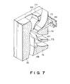
- a latent image-bearing member 1 is an insulating drum for electrostatic recording or a photosensitive drum or belt comprising a layer of a photoconductive material such as a-Se, CdS, Sn0 2 , OPC (organic photoconductor) and a-Si.
- the latent image bearing member 1 is driven in the direction indicated by an arrow a by an unshown driving device.
- the developing device includes a developing sleeve 22 which is opposed or caused to contact the image bearing member 1 and is made of non-magnetic material such as aluminum, SUS 316 (stainless steel, JIS).
- the developing sleeve 22 is in a longitudinal opening formed in a lower left wall of a developer container 36, and about a right half peripheral surface is in the container 36, whereas about a left half peripheral surface thereof is exposed outside.
- the developing sleeve 22 is rotatably supported and is driven in the direction indicated by an arrow b.
- the developing device further includes a stationary magnetic field generating means 23 in the form of a stationary permanent magnet within the developing sleeve 22.
- the permanent magnet 23 is fixed and is maintained stationary even when the developing sleeve 22 is rotated.
- the magnet 23 has an N-pole 23a, S-pole 23b, N-pole 23c and an S-pole 23d, that is, it has four poles.
- the magnet 23 may be an electromagnetic one in place of the permanent magnet.
- a non-magnetic blade 24 has a base portion fixed to a side wall of the container adjacent a top edge of the opening in which the developing sleeve 22 is disposed, and a free end extending at a top edge of the opening.
- the blade 24 serves to regulate the developer carried on the developing sleeve 22.
- the non-magnetic blade is made by, for example, bending to "L" shape a stainless steel plate (SUS316).
- the developing device includes a magnetic carrier particle limiting member 26 which is disposed so that the upper surface thereof contacts the lower surface of the non-magnetic blade 24.
- the bottom surface 261 of the limiting member 26 constitutes a developer guiding surface.
- the non-magnetic blade 24, the magnetic particle limiting member 26, etc., define a developer regulating station.
- the reference numeral 27 designates magnetic carrier particles having a resistivity of not less than 10 7 ohm.cm, preferably not less than 10 8 ohm.cm, more preferably 10 9 - 10 12 ohm.cm.
- carrier particles ferrite particles (maximum magnetization 55 - 75 emu/g) are coated with a resin.
- the reference numeral 37 designates non-magnetic toner.
- a sealing member 40 is effective to prevent the toner stagnating adjacent the bottom of the developer container 36 from leaking.
- the sealing member 40 is bent co-directionally with the rotation of the sleeve 22, and is resiliently pressed onto the surface of the sleeve 22.
- the sealing member 40 has its end portion at a downstream side in the region where it is contacted to the sleeve 22 so as to allow the developer returning into the container.
- An electrode plate 30 for preventing scattering of the floating toner particles produced by the developing process is supplied with a voltage having a polarity which is the same as the polarity of the toner to cause the toner particles to be deposited on the photosensitive member.
- a toner supplying roller 160 is operative in response to an output of an unshown toner content detecting sensor.
- the sensor may be, for example, of a developer volume detecting type, a piezoelectric element type, an inductance change detecting type, an antenna type utilizing an alternating bias, or an optical density detecting type.
- the S-pole 23d is a conveying pole for collecting the developer remaining after the developing operation back into the container, and to convey the developer in the container to the regulating portion, by the magnetic field provided thereby.
- the fresh developer conveyed by the screw 162 adjacent the sleeve 22 replaces the developer on the sleeve 22 collected after the development.
- a conveying screw 164 is effective to make uniform the distribution of the developer amount along the length of the developing sleeve.
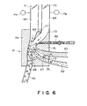
- the distance d 2 between the edge of the non-magnetic blade 24 and the surface of the developing sleeve 22 is 100 - 900 ⁇ m, preferably 150 - 800 ⁇ m. If the distance is smaller than 100 ⁇ m, the magnetic carrier particles may clog the clearance to easily produce non-uniform developer layer, and to prevent application of sufficient amount of the developer with the result of low density and non-uniform density image. Further, the clearance d 2 is preferably not less than 400 ⁇ m since then it can be avoided that a non-uniform developer layer (clogging at the blade) is produced by foreign matter contained in the developer.
- the distance is larger than 900 ⁇ m, the amount of the developer applied on the developing sleeve 22 is increased too much, and therefore, proper regulation of the thickness of the developer layer can not be performed, and the amount of the magnetic particles deposited on the latent image bearing member is increased, and simultaneously, the circulation of the developer which will be described hereinafter and the regulation of the circulation by the developer limiting member 26 are weakened with the result of insufficient triboelectric charge leading to production of foggy background.
- a line L1 is a line connecting a rotational center of the sleeve 22 and the center of the developer layer thickness regulating pole 23a, that is, the maximum magnetic flux density position on the sleeve surface
- a line L2 is a line connecting the rotational center of the sleeve 22 and the free edge of the blade 24
- an angle 01 is an angle formed between the lines L1 and L2.
- the angle 01 is within the range of-5 - 35 degrees, preferably 0 - 25 degrees.
- the 01 is smaller than -5 degrees, the developer layer formed by the magnetic force, mirror force and coagulating force applied to the developer becomes non-uniform, whereas if it is larger than 35 degrees, the amount of application of the developer on the sleeve by a non-magnetic blade is increased with the result of difficulty in providing a predetermined amount of developer.
- the negative of the angle 01 means that the line L1 is disposed downstream of the line L2 with respect to the rotational direction of the sleeve 22.
- the speed of the developer layer on the sleeve 22 becomes lower away from the sleeve surface due to the balance between the conveying force by the sleeve 22 and the gravity and the magnetic force against it, even though the sleeve 22 is rotated in the direction indicated by an arrow b. Some part of the developer falls by the gravity.
- the developer layer is moved more in the position closer to the sleeve 22, to constitute a moving layer.
- the developer is conveyed to a developing position together with the rotation of the sleeve 2, and is provided for the developing operation.
- Figure 2 is a graph illustrating the developing method according to the present invention.
- Figure 2 shows an alternating electric field used in a case where a developer is supplied to a developing position (minimum clearance: G ( ⁇ m)) where an electrostatic image-bearing member is disposed opposite to a developer-carrying member carrying thereon a developer.
- the developer used herein comprises toner particles, and magnetic particles capable of being charged at a polarity reverse to that of the toner particles.
- the alternating electric field shown by Figure 2 has a rectangular waveform.
- V D (V) the electrostatic image potential
- VppMax (V) at the maximum electric field application point is the maximum point of the rectangular wave on the positive side (i.e., upper portion in Figure 2), and the background potential becomes V L (V).
- the carrier (magnetic) particles can be attached to an image portion to disturb it.
- the background part potential V D is set to -600 V
- the electrostatic image potential is set to -250 V
- a DC component is set to -490 V in order to prevent the attachment of toner particles to the background part.
- Figure 2 may facilitate the understanding the developing method according to the present invention.
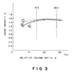
- the maximum electric field strength F (V/pm) in the image area is expressed as where
- VppMax (V) is the voltage at the maximum electric field application point which is at the opposite side of the image portion potential V L with respect to the potential V ⁇ ;
- G (pm) is the minimum clearance between the surface of the image bearing member (sleeve) and the surface of the electrostatic latent image bearing member (photosensitive member).
- the attachment of the magnetic particles is prevented and the gradational characteristic is good in the range of 1.5 ⁇ F ⁇ 3.5.
- F > 3.5 the magnetic particles are uniformly attached to the image portion at a certain proportion, the transparency of the whole image is impaired and image unevenness occurs at the time of transfer.
- F ⁇ 1.5 the attachment of the magnetic particles is effectively prevented but the sharpness of line images is lowered and the image density is lowered.
- a relationship of 1.5 ⁇ F ⁇ 3.0 (more preferably 2 - F Z 3.0) is further preferred.
- the developing efficiency is high and is effective in the case of an image of large area and a large toner consumption such as full-color copying.
- the developer because the developer is reciprocated, the toner particles are liable to be released from the magnetic particles, whereby toner scattering is liable to occur.
- the developer may desirably be one having a function of reducing the toner scattering.
- the magnetic particles can be attached to the non-image area in addition to the image area, but in the present invention, the attachment of the magnetic particles to the non-image area may suitably be prevented because of the above-mentioned reason.
- V DC -V L the absolute value of V DC - V L is preferably not more than 150 (V).
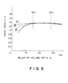
- Additional conditions are 0.8 ⁇ ⁇ ⁇ 3.0 (more preferably 0.8 ⁇ ⁇ ⁇ 2.2), where v is a frequency (KHz) of the alternating electric field. If the frequency is below 0.8 KHz, fog increases. If the frequency is above 2.2 KHz (particularly, above 3.0 KHz), the sharpness and gradational characteristic of a line image deteriorate.
- KHz a frequency of the alternating electric field
- the developer layer may be in contact with the latent image bearing member or not, under no application of an alternating electric field.
- the fluidity improver having a weak chargeability contained in the developer has a weak adhesion force to a latent image formed on a photosensitive member, it has a tendency not to be consumed in a developing step but to be accumulated in a developing device.
- the fluidity improver because the fluidity improver have a rich opportunity to contact the photosensitive member, the above-mentioned tendency may be obviated.
- the relative volumetric ratio defines the amount of the developer conveyed into the developing position in the developing device having the structure described above.
- the relative volumetric ratio is defined in the developing position or zone where the toner particles are transferred or supplied from the sleeve 22 to the photosensitive drum 1.
- the relative volumetric ratio is defined by an amount M (g/cm 2 ) of the developer (mixture of the magnetic carrier particles and toner particles) per a unit area of the surface of the sleeve 22, a height h (cm) of the developing zone space (the distance between the sleeve surface and the drum surface), a true density p (g/cm 3 ) of the magnetic carrier particles, weight content of the carrier particles on the surface of the sleeve C/(T+C) (%) (C is a weight of the carrier particles, and T is a weight of the toner particles), and a relative speed ratio a between the sleeve 22 and the photosensitive member 1. More particularly, the relative volumetric ratio Q is defined as
- the relative volumetric ratio Q is influenced by the structure of the developing device described hereinbefore, more particularly, by the positions of the magnetic poles of the magnet roller 23, the strengths of the magnetic poles, configuration of the developer limiting member 26, or the distance d 2 between the edge of the non-magnetic blade 24 and the surface of the sleeve 22.
- the relative volumetric ratio Q considerably affects copied images, particularly their image density.
- the above-mentioned developing conditions as a preferred embodiment of the developing method according to the present invention is those based on the following discovery.
- the image density and image quality are not monotonously changed depending on the amount of a developer to be applied onto the sleeve 22 and an increase or decrease in the developing zone space.
- the above-mentioned relative volumetric ratio Q i.e., the volumetric amount of the magnetic particles passing through the developing zone per unit time
- the ratio Q is smaller than 15.0 % or larger than 45.0 %, there occur somewhat decrease in the image density and a decrease in image quality which are not desirable in a color Copy image.
- sleeve ghost i.e., unevenness in the toner coating in a portion wherein toner particles have been consumed it the prior developing step or fog does not occur when the ratio Q is in the above-mentioned range providing the above-mentioned sufficient image quality.
- the chains (or ears) of the carrier particles are formed on the sleeve surface 22 and are distributed sparsely to a satisfactory extent, so that the toner particles on the chain surfaces and those on the sleeve surfaces are sufficiently opened toward the photosensitive drum 1, and the toner 102 on the sleeve are transferred to the photosensitive drum 1 under the existence of the alternating electric field.
- the development efficiency the ratio of the toner consumable for the development to the overall toner present in the developing position
- a high image density can be provided.
- the fine but violent vibration of the carrier chains is preferably produced by the alternating electric field, by which the toner powder deposited on the magnetic particles and the sleeve surface are sufficiently loosened. In any case, the trace of brushing or occurrence of the ghost image as in the magnetic brush development can be prevented. Additionally, the vibration of the chains enhances the frictional contact between the magnetic particles 27 and the toner particles 28, with the result of the increased triboelectric charging to the toner particles 28, by which the occurrence of the foggy background can be prevented.
- the range of the relative volumetric ratio Q is as described above. Further the ratio of the sleeve peripheral speed to that of the photosensitive member, that is the relative speed ratio a is 1.2 ⁇ ⁇ ⁇ 2.5.
- the relative speed ratio a used herein is represented by the following formula:
- the developing efficiency may be increased. If the relative speed ratio ⁇ > 2.5, the image density in the solid image is not uniform, in such a form as when powder is swept together.
- Coulter counter Model TA-II (available from Coulter Electronics Inc.) is used as an instrument for measurement, to which an interface (available from Nikkaki K.K.) for providing a number-basis distribution, a volume-basis distribution, a number-average particle size and a volume-average particle size, and a personal computer CX-1 (available from Canon K.K.) are connected.
- an interface available from Nikkaki K.K.
- CX-1 available from Canon K.K.
- a 1 %-NaCI aqueous solution as an electrolytic solution is prepared by using a reagent grade sodium chloride.
- a surfactant preferably an alkylbenzenesulfonic acid salt
- 0.5 to 50 mg, preferably 2 to 20 mg, of a sample is added thereto.
- the resultant dispersion of the sample in the electrolytic liquid is subjected to a dispersion treatment for about 1 - 3 minutes by means of an ultrasonic disperser, and then subjected to measurement of particle size distribution in the range of 2 - 40 microns by using the above-mentioned Coulter counter Model TA-II with a 100 microns-aperture to obtain a volume-basis distribution and a number-basis distribution. From the results of the volume-basis distribution and number-basis distribution, the volume-average particle size, the percentage (%) by number of toner particles having particle sizes of below 6.35 ⁇ m, and the percentage (%) by volume of particles having particle sizes of above 16.0 ⁇ m of the sample toner are calculated.
- An instrument as shown in Figure 4 is used, for measurement of a triboelectric charge.
- a mixture comprising sample particles to be measured and magnetic particles used herein.
- toner particles or colored resin particles 5 g of such particles are mixed with 95 g of magnetic particles.
- 2 g of fluidity improver is mixed with 98 g of magnetic particles.
- the sample partioles and the magnetic particles used for the measurement are left standing for at least 12 hours in the environment of 23 °C and 60 % RH before the measurement.
- the measurement of triboelectric charge is also conducted in the environment of 23 °C and 60 %RH.
- the above-mentioned mixture is charged in a polyethylene bottle with a volume of 100 ml and reciprocally shaked by means of a turbula mixer (3 cycles/sec) sufficiently (e.g., 60 times). Then, the shaken mixture (sample particles + magnetic particles) is charged in a metal container 112 for measurement provided with a 500- mesh screen 113 at the bottom as shown in Figure 4 and covered with a metal lid 114. Incidentally the mesh size can appropriately be changed so that the magnetic particles do not pass through the screen 113. The total weight of the container 112 is weighed and denoted by W 1 (g).
- an aspirator 111 composed of an insulating material at least with respect to a part contacting the container 112 is operated, and the toner in the container is removed by suction through a suction port 117 sufficiently (preferably for about two minutes) while controlling the pressure at a vacuum gauge 115 at 250 mm.Aq. by adjusting an aspiration control valve 116.
- the reading at this time of a potential meter 119 connected to the container by the medium of a capacitor 118 having a capacitance C (pF) is denoted by V (volts).
- the total weight of the container after the aspiration is measured and denoted by W 2 (g).
- the triboelectric charge ( ⁇ c/g) of the sample is calculated as: CxV/(W i - W 2 ).
- the magnetic particles used for the measurement are ferrite particles coated with a styrene type resin and comprise 70 wt. % or more, preferably 75 - 95 wt. %, of particles having sizes between 250 to 400 mesh. More specifically, the particles are ferrite particles coated with 0.2 - 0.7 wt. % of a styrene-2-ethylhexyl acrylate- methyl methacrylate copolymer.
- Flow Tester Model CFT-500 (available from Shimazu Seisakusho K.K.) is used. Powder having passed through a 60-mesh sieve is used as a sample and weighed in about 1.0 to 1.5 g. The sample is pressed under a pressure of 100 kg/cm 2 for 1 minute by using a tablet shaper.
- the pressed sample is subjected to measurement by means of Flow Tester in an environment of temperature of about 20 to 30 °C and relative humidity of 30 - 70 % under the following conditions:
- the resistivity of the magnetic particles is measured with a sandwiching type cell having a measuring electrode area of 4 cm 2 and having a clearance of 0.4 cm between the electrodes.
- One of the electrodes is imparted with 1 kg weight, and a voltage E(V/cm) is applied across the electrodes, and the resistivity of the magnetic particles is determined from the current through the circuit.
- the agglomeration degree is used as a measure for evaluating the fluidity of a sample (e.g., a toner composition containing an external additive). A higher agglomeration degree is judged to represent a poorer fluidity of the sample.
- Powder Tester available from Hosokawa Micron K.K. is used.
- a 60-mesh sieve, a 100 mesh-sieve and a 200-mesh sieve are superposed in this order from the above and set on a vibration table.
- An accurately measured sample in an amount of 5 g is placed on the 60-mesh sieve, and the vibration table is subjected to vibration for about 15 seconds under the conditions of an input voltage to the vibration table of 21.7 V, and a vibration amplitude in the range of 60 - 90 microns (a rheostat scale: about 2.5).
- the weights of the sample remaining on the respective sieves are measured to calculate the agglomeration from the following equation:
- the sample before the measurement is left standing under the conditions of 23 °C and 60 %RH and is subjected to measurement under the conditions of 23 °C and 60 %RH.
- hydrophobicity of silica fine powder having a surface imparted with a hydrophobicity is measured by the methanol titration test, which is conducted as follows.
- Sample silica fine powder (0.2 g) is charged into 50 ml of water in a 250 ml-Erlenmeyer's flask. Methanol is added dropwise from a buret until the whole amount of the silica is wetted therewith. During this operation, the content in the flask is constantly stirred by means of a magnetic stirrer. The end point can be observed when the total amount of the fine silica particles is suspended in the liquid, and the hydrophobicity is represented by the percentage of the methanol in the liquid mixture of water and methanol on reaching the end point.
- Powder Tester (available from Hosokawa Micron K.K.) is used for measurement of the apparent density.
- a 60-mesh sieve is placed on a vibration table, and right under the sieve, a preliminarily weighed 100 cc-cup for measurement of apparent density is placed. Then, vibration is started at a rheostat scale of 2.0.
- a sample is gently poured on the vibrating 60-mesh sieve so as to pass through the sieve into the cup. When the cup is filled with a heap of the sample, the vibration is terminated and the heap of the sample is leveled at the top of the cup. Then, the sample is weighed accurately by a balance.
- the apparent density (g/cm 3 ) of the sample is obtained as the sample weight (g)/100.
- the sample before the measurement is left standing under the conditions of 23 °C and 60 %RH and is subjected to measurement under the conditions of 23 °C and 60 %RH.
- DSC stands for differential scanning colorimetry.
- a differential scanning calorimeter DSC 7 (available from Perkin Elmer Corp.) is used.
- sample is accurately weighed in 5 - 20 mg, preferably about 10 mg.
- the sample is placed on an aluminum pan with the used of an empty aluminum pan as the reference and is subjected to DSC in the temperature range of 30 °C to 200 °C at a temperature raising rate of 10 °C/min in the environment of normal temperature and normal humidity.
- the absorption peak referred to herein is a temperature at which a main absorption peak is observed in the temperature range of 40 - 100 °C.
- the toner or developer according to the present invention can further contain another optional additive.
- lubricants including fatty acid metal salts such as zinc stearate and aluminum stearate, and fine powder of fluorine-containing resins such as polytetrafluoroethylene, polyvinylidene fluoride and tetrafluoroethylene-vinylidene fluoride copolymer; abrasives such as cerium oxide and silicon carbide; and electroconductivity-imparting agent such as tin oxide and zinc oxide.
- the colored resin particles according to the present invention may be produced by sufficiently mixing thermoplastic resin such as those enumerated hereinbefore and a pigment or dye as colorant, and optionally, a charge controller, another additive, etc., by means of a mixer such as a ball mill, etc.; then melting and kneading the mixture by hot kneading means such as hot rollers, kneader and extruder to disperse or dissolve the pigment or dye, and optional additives, if any, in the melted resin; cooling and crushing the mixture; and subjecting the powder product to precise classification to form colored resin particles according to the present invention.
- a mixer such as a ball mill, etc.
- hot kneading means such as hot rollers, kneader and extruder to disperse or dissolve the pigment or dye, and optional additives, if any, in the melted resin
- cooling and crushing the mixture and subjecting the powder product to precise classification to form colored resin particles according to the present invention.
- a mixture containing the above ingredients in the prescribed amounts was sufficient pre-mixed by means of a Henschel mixer and then melt-kneaded on a three-roll mill at least two times. After cooling, the kneaded product was coarsely crushed to about 1 - 2 mm by using a hammer mill and then finely pulverized by means of a pulverizer based on an air-jet system. The fine pulverized product was classified by means of a multi-division classifier to obtain negatively chargeable cyan-colored resin particles.
- the thus obtained colored resin particles had a volume-average particle size of 8.3 ⁇ m; a number-bias distribution wherein the proportion of particles having a particle size of 5 ⁇ m or below was 25 % by number and the proportion of particles having a particle size of 6.35 - 10.1 ⁇ m was 46 % by number; and a volume-basis distribution wherein the proportion of particles having a particle size of 6.35 - 10.1 ⁇ m was 67 % by volume, the proportion of particles having a particle size of 12.7 -16.0 ⁇ m was 1.6 % by volume, and the proportion of particles having a particle size of above 16.0 ⁇ m was zero %.
- the thus obtained cyan toner had an apparent viscosity of 6.00x10 5 poise (at 90 °C) and 1.1x10 4 poise (at 100 °C), an apparent density of 0.35 g/cm 2 , and a heat-absorption peak according to DSC of 67.2 °C.
- the ferrite particles used herein had a volume-average particle size of 52 ⁇ m, and contained substantially zero % of magnetic particles having a particle size of 10 ⁇ m or below; 3 wt. % of magnetic particles having a particle size of below 26 ⁇ m; 9 wt. % of magnetic particles having a particle size of 26 or above and below 35 ⁇ m; 12 wt. % of magnetic particles having a particle size of 35 ⁇ m or above and below 43; and 0.1 wt. % of magnetic partaicles having a particle size of 74 ⁇ m or above.
- the thus prepared developer was charged in a developing device as shown in Figure 1, wherein the clearance between a developing sleeve 22 and a cut blade 24 was set to 650 ⁇ m.
- the developing device was assembled in a color laser copying machine using a digital developing system and a reversal developing system (trade name: PIXEL, mfd. by Canon K.K.) which had been modified so as to effect reversal development.
- the clearance between a photosensitive drum 1 (outside diameter: 80 mm) comprising an organic photoconductor (OPC), and the sleeve 22 (outside diameter: 32 mm) was set to 500 ⁇ m, and the peripheral speed ratio ⁇ between the photosensitive drum 1 and the developing sleeve 22 was set to 1.7.
- the photosensitive drum 1 was charged so as to have a latent image potential of-700 V and was imagewise exposed to light to have an exposure latent image potential of -150 V.
- a bias voltage obtained by an AC voltage having a frequency of 2000 Hz and a peak-to-peak value of 2000 V on a DC voltage of -550 V.
- the relative volume ratio Q was 25.7 (%), and the maximum electric field intensity F was 2.80 (V/ ⁇ m).
- the multi-division classifier has side walls 72, 73 and 74, and a lower wall 75.
- the side wall 73 and the lower wall 75 are provided with knife edge-shaped classifying wedges 67 and 68, respectively, whereby the classifying chamber is divided into three sections.
- a feed supply nozzle 66 opening into the classifying chamber is provided at a lower portion of the side wall 72.
- a Coanda black 76 is disposed along the lower tangential line of the nozzle 66 so as to form a long elliptic arc shaped by bending the tangential line downwardly.
- the classifying chamber has an upper wall 77 provided with a knife edge-shaped gas-intake wedge 69 extending downwardly.
- gas-intake pipes 64 and 65 opening into the classifying chamber are provided.
- a first gas introduction control means 70 and a second gas introduction control means 71, respectively, comprising, e.g., a damper, are provided; and also static pressure gauges 78 and 79 are disposed communicatively with the pipes 64 and 65, respectively.
- exhaust pipes 61, 62 and 63 having outlets are disposed corresponding to the respective classifying sections and opening into the chamber.
- Feed powder to be classified is introduced into the classifying zone through the supply nozzle 66 under reduced pressure.
- the feed powder thus supplied are caused to fall along curved lines 80 due to the Coanda effect given by the Coanda block 76 and the action of the streams of high-speed air, so that the feed powder is classified into coarse powder 61, cyan-colored fine powder 62 having prescribed volume-average particle size and particle size distribution, and ultra-fine powder 63.
- Colored resin particles were prepared in the same manner as in Example 1 except that micropulverization and classification conditions were controlled to obtain colored resin particles having characteristics as shown in Table 1 appearing hereinafter.
- the thus obtained colored resin particles had a volume-average particle size of 8.0 ⁇ m; a number-bias distribution wherein the proportion of particles having a particle size of 5 ⁇ m or below was 36 % by number and the proportion of particles having a particle size of 6.35 - 10.1 ⁇ m was 38 % by number; and a volume-basis distribution wherein the proportion of particles having a particle size of 6.35 - 10.1 ⁇ m was 65 % by volume, the proportion of particles having a particle size of 12.7 -16.0 ⁇ m was 1.6 % by volume, and the proportion of particles having a particle size of above 16.0 ⁇ m was zero %.
- a two-component developer was prepared in the same manner as in Example 1 except that the above-prepared colored resin particles were used, and the thus obtained developer was subjected to an image formation test in the same manner as in Example 1. The results are shown in Table 3 appearing hereinafter.
- colored resin particles were prepared in the same manner as in Example 1, to obtain magenta-colored resin particles having characteristics as shown in Table 1 appearing hereinafter.
- the thus obtained colored resin particles had a volume-average particle size of 8.5 ⁇ m; a number-bias distribution wherein the proportion of particles having a particle size of 5 ⁇ m or below was 18 % by number and the proportion of particles having a particle size of 6.35 - 10.1 ⁇ m was 55 % by number; and a volume-basis distribution wherein the proportion of particles having a particle size of 6.35 - 10.1 ⁇ m was 69 % by volume, the proportion of particles having a particle size of 12.7 -16.0 ⁇ m was 2.6 % by volume, and the proportion of particles having a particle size of above 16.0 ⁇ m was 0.1 % by volume.
- a two-component developer was prepared in the same manner as in Example 1 except that the above-prepared colored resin particles were used, and the thus obtained developer was subjected to an image formation test in the same manner as in Example 1. The results are shown in Table 3 appearing hereinafter.
- colored resin particles were prepared in the same manner as in Example 1, to obtain negatively chargeable yellow-colored resin particles having characteristics as shown in Table 1 appearing hereinafter.
- the thus obtained colored resin particles had a volume-average particle size of 7.7 ⁇ m; a number-basis distribution wherein the proportion of particles having a particle size of 5 ⁇ m or below was 31 % by number and the proportion of particles having a particle size of 6.35 - 10.1 ⁇ m was 42 % by number; and a volume-basis distribution wherein the proportion of particles having a particle size of 6.35 - 10.1 ⁇ m was 65 % by volume, the proportion of particles having a particle size of 12.7 -16.0 ⁇ m was 0.5 % by volume, and the proportion of particles having a particle size of above 16.0 ⁇ m was zero %.
- Hydrophobic silica and alumina powder were mixed with the above-mentioned yellow-colored resin particles in the same manner as in Example 1 to obtain a yellow toner.
- Atwo-component developer was prepared by mixing the yellow toner with ferrite carrier coated with a resin in the same manner as in Example 1, and the thus obtained developer was subjected to an image formation test in the same manner as in Example 1. The results are shown in Table 3 appearing hereinafter.
- Cyan toners were prepared in the same manner as in Example 1 except that colored resin particles and fluidity improvers as shown in Tables 1 and 2 were respectively used, and were subjected to an image formation test in the same manner as in Example 1. The results are shown in Table 3 appearing hereinafter.
- Example 1 As apparent from Table 3, the toner obtained in Example 1 was particularly excellent in durability and fog, as compared with those obtained in Examples 5 - 8.
- Cyan-colored resin particles were prepared in the same manner as in Example 1 except that micropulverization and classification conditions were controlled to obtain colored resin particles having characteristics as shown in Table 1 appearing hereinafter.
- the thus obtained colored resin particles had a volume-average particle size of 11.1 ⁇ m; a number-basis distribution wherein the proportion of particles having a particle size of 5 ⁇ m or below was 8 % by number and the proportion of particles having a particle size of 6.35 - 10.1 ⁇ m was 52 % by number; and a volume-basis distribution wherein the proportion of particles having a particle size of 6.35 - 10.1 ⁇ m was 36 % by volume, the proportion of particles having a particle size of 12.7 - 16.0 ⁇ m was 20.2 % by volume, and the proportion of particles having a particle size of above 16.0 ⁇ m was 3.0 % by volume.
- a cyan toner and a two-component developer were prepared in the same manner as in Example 1 except that the above-prepared colored resin particles were used, and the thus obtained developer was subjected to an image formation test in the same manner as in Example 1.
- the results are shown in Table 3 appearing hereinafter.
- a full-color copy image was formed in the same manner as in Example 1 except for using the two-component developer containing the cyan toner obtained in Example 1, the two-component developer containing the magenta toner obtained in Example 3, and the two-component developer containing the yellow toner obtained in Example 4.
- a mixture containing the above ingredients in the prescribed amounts was sufficient pre-mixed by means of a Henschel mixer and then melt-kneaded on a three-roll mill at least two times. After cooling, the kneaded product was coarsely crushed to about 1 - 2 mm by using a hammer mill and then finely pulverized by means of a pulverizer based on an air-jet system. The fine pulverized product was classified to obtain negatively chargeable cyan-colored resin particles of 2 - 10 ⁇ m having a volume-average particle size of 7.8 ⁇ m.
- the thus obtained particles had an apparent viscosity of 6.00x10 5 poise (at 90 °C) and 1.1x10 4 poise (at 100 °C).
- 100 wt. parts of the above-mentioned colored resin particles was mixed with 0.3 wt. part of alumina fine powder (charge amount: -4 ⁇ c/g) having a BET specific surface area of 100 m 2 /g, and 0.5 wt. part of silica fine powder (charge amount: -80 ⁇ c/g) having a BET specific surface area of 250 m 2 /g which had been treated with a hydrophobicity-imparting agent (hexamethyldisilazane), to obtain a cyan toner.
- alumina fine powder charge amount: -4 ⁇ c/g
- silica fine powder charge amount: -80 ⁇ c/g having a BET specific surface area of 250 m 2 /g which had been treated with a hydrophobicity-imparting agent (hexa
- the thus prepared developer was charged in an ordinary copying machine for plain paper (CLC-1, mfd. by Canon K.K.) and was subjected to successive copying of 30,000 sheets under normal temperature-normal humidity conditions (23 °C, 60 %RH), low temperature-low humidity conditions (15 °C, 10 %RH) and high temperature-high humidity conditions (32.5 °C, 85 %RH).
- normal temperature-normal humidity conditions 23 °C, 60 %RH
- low temperature-low humidity conditions 15 °C, 10 %RH
- high temperature-high humidity conditions 32.5 °C, 85 %RH
- a two-component developer was prepared in the same manner as in Example 10 except that 0.8 wt. part of silica fine powder having a BET specific surface area of 100 m 2 /g treated with dimethyldichlorosilane (triboelectric charge amount: -130 wc/g) was used alone as a fluidity improver.
- the thus prepared developer was subjected to successive copying in the same manner as in Example 10. As a result, image density was lowered under low temperature-low humidity conditions, and the image density was further lowered along with the progress in the successive copying.
- a two-component developer was prepared in the same manner as in Example 10 except that 0.7 wt. part of alumina fine powder having a BET specific surface area of 120 m 2 /g (triboelectric charge amount: -4 ⁇ c/g) was used alone as a fluidity improver.
- Example 11 The thus prepared developer was subjected to successive copying in the same manner as in Example 10. As a result, good images were obtained in the initial stage but toner scattering in the successive copying was marked as compared that in Example 10, and fog occurred in the resultant image. Further, when the same copying was conducted while decreasing the toner concentration to 4 %, the evaluation of toner scattering and fog was poorer than those in Example 10. Further, under high temperature-high humidity (H/H) conditions, the developer of Example 11 provided a high image density but change in its performance with respect to environmental condition change was larger than that of Example 10.
- H/H high temperature-high humidity
- a two-component developer was prepared in the same manner as in Example 10 except that 0.5 wt. part of silica fine powder having a BET specific surface area of 250 m 2 /g treated with hexamethyldisilazane (triboelectric charge amount: -150 wcg) and 0.3 wt. part of alumina fine powder having a BET specific surface area of 200 m 2 /g (triboelectric charge amount: -4 ⁇ c/g) were used as a fluidity improver in combination.
- the thus prepared developer was subjected to successive copying in the same manner as in Example 10.
- the mixability with the magnetic particles was poor and there occurred toner particles insufficiently charged triboelctrically, and fog became noticeable after about 500 sheets of copying.
- red powder having a volume-average particle size of 6.5 ⁇ m was prepared in the same manner as in Example 10.
- the thus prepared developer was charged in commercially available copying machine for plain paper (NP-COLOR T, mfd. by Canon K.K.) and was subjected to successive copying of 10,000 sheets under the same conditions as in Example 10. As a result, high-quality images having a sufficiently high image density were obtained under any of these conditions.
- a two-component developer was prepared in the same manner as in Example 10 except that silica fine powder having a BET specific surface area of 250 m 2 /g treated with hexamethyldisilazane (triboelectric charge amount: - 80 ⁇ c/g) and titanium oxide fine powder having a BET specific surface area of 40 m 2 /g (triboelectric charge amount: +5 ⁇ c/g) treated with octyltrimethoxysilane were used as a fluidity improver.
- a yellow toner having a volume-average particle size of 7.5 ⁇ m was prepared in the same manner as in Example 10 except that 3.5 parts of C.I. Pigment Yellow 17 was used instead of the phthalocyanine pigment.
- a magenta toner having a volume-average particle size of 7.6 ⁇ m was prepared in the same manner as in Example 10 except that 0.9 part of C.I. Solvent Red 4a and 1.0 part of C.I. Solvent 52 were used instead of the phthalocyanine pigment.
- a black toner having a volume-average particle size of 7.5 ⁇ m was prepared in the same manner as in Example 10 except that 1.2 part of C.I. Pigment Yellow 17, 2.8 parts of C.I. Pigment Red 5 and 1.5 parts of C.I. Pigment Blue 15 were used instead of the phthalocyanine pigment.
- Example 10 The above-mentioned yellow, magenta and black toners, and the cyan toner obtained in Example 10 were respectively mixed with the magnetic particles used in Example 10 to prepare developers of respective colors.
- a developer which is capable of providing a high-quality image having good color reproducibility and capable of showing good environmental characteristic even when environmental conditions are changed.
- a mixture containing the above ingredients in the prescribed amounts was sufficient pre-mixed by means of a Henschel mixer and then melt-kneaded on a three-roll mill at least two times. After cooling, the kneaded product was coarsely crushed to about 1 - 2 mm by using a hammer mill and then finely pulverized by means of a pulverizer based on an air-jet system. The fine pulverized product was classified to obtain colored resin particles of 2 - 10 ⁇ m having a volume-average particle size of 7.8 ⁇ m.
- rosin particles had an apparent viscosity of 6.00x10 5 poise (at 90 °C) and 1.1x1 04 poise (at 100 °C).
- 100 wt. parts of the above-mentioned colored resin particles was mixed with 0.6 wt. part of alumina fine powder (charge amount: +1.7 wc/g with respect to magnetic particles described below) having a BET specific surface area of 100 m 2 /g, and 0.4 wt. part silica fine powder (charge amount: -85 ⁇ c/g) by external addition to obtain a cyan toner.
- alumina fine powder charge amount: +1.7 wc/g with respect to magnetic particles described below
- silica fine powder charge amount: -85 ⁇ c/g
- the above-mentioned colored resin particles were triboelectrically charged to have a charge amount of - 32 wc/g when charged by using the above ferrite particles.
- Figure 3 is a graph showing a relationship between the relative volumetric ratio (Q) and the image density when the above-mentioned cyan developer was used.
- the above prepared developer was charged in a developing device as shown in Figure 1, wherein the clearance between a developing sleeve 22 and a cut blade 24 was set to 650 ⁇ m.
- the developing device was assembled in a copying machine (trade name: PC-10, mfd. by Canon K.K.) which had been modified so as to effect reversal development.
- the clearance between a photosensitive drum 1 (outside diameter: 60 mm) comprising an organic photoconductor (OPC), and the sleeve 22 (outside diameter: 20 mm) was set to 350 ⁇ m, and the peripheral speed ratio a between the photosensitive drum 1 and the developing sleeve 22 was set to 1.5.
- the photosensitive drum 1 was charged to have a latent image potential of -600 V and was imagewise exposed to light to have an exposure latent image potential of -250 V.
- a bias voltage obtained by an AC voltage having a frequency of 1800 Hz and a peak-to-peak value of 1400 V on a DC voltage of -490 V.
- the relative volume ratio Q was 25.7 (%), and the maximum electric field intensity F was 2.69 (V/ ⁇ m).
- a two-component developer was prepared in the same manner as in Example 15 except that titanium oxide fine powder having a BET specific surface area of 50 m 2 /g (triboelectric charge amount: -3.3 ⁇ c/g) was used as a fluidity improver, instead of the alumina.
- the thus prepared developer was subjected to successive copying in the same manner as in Example 15. As a result, good color images were obtained.
- a two-component developer was prepared in the same manner as in Example 15 except that hydrophobic fine powder having a BET specific surface area of 200 m 2 /g treated with dimethyldichlorosilane (triboelectric charge amount: -140 ⁇ c/g with respect to magnetic particles used in this instance) was used as a fluidity improver.
- the thus prepared developer was subjected to successive copying in the same manner as in Example 15. As a result, image density was lowered and image unevenness occurred under low temperature-low humidity conditions.
- a yellow toner having a volume-average particle size of 7.5 ⁇ m was prepared in the same manner as in Example 15 except that 3.5 parts of C.I. Pigment Yellow 17 was used instead of the phthalocyanine pigment.
- a magenta toner having a volume-average particle size of 7.6 ⁇ m was prepared in the same manner as in Example 15 except that 0.9 part of C.I. Solvent Red 4a and 1.0 part of C.I. Solvent 52 were used instead of the phthalocyanine pigment.
- a black toner having a volume-average particle size of 7.5 ⁇ m was prepared in the same manner as in Example 15 except that 1.2 part of C.I. Pigment Yellow 17, 2.8 parts of C.I. Pigment Red 5 and 1.5 parts of C.I. Pigment Blue 15 were used instead of the phthalocyanine pigment.
- Example 15 The above-mentioned yellow, magenta and black toners, and the cyan toner obtained in Example 15 were respectively mixed with the magnetic particles used in Example 15 to prepare developers of respective colors.
- toners were applied to a modification of a full-color laser copying machine (PIXEL, mfd. by Canon K.K.).
- the photosensitive drum was charged to have a latent image potential of-550 V and was imagewise exposed to light to have an exposure latent image potential of -165 V.
- a bias voltage obtained by an AC voltage having a frequency of 2000 Hz and a peak-to-peak value of 1800 V on a DC voltage of -440 V.
- the peripheral ratio a was 1.75
- the relative volume ratio Q was (23 ⁇ 3) (%)
- the maximum electric field intensity F was 2.44 (V/ ⁇ m).
- the respective colored resin particles had a charge amount as follows:
- a two-component developer was prepared and the developer was subjected to image formation in the same manner as in Example 15 except that magnetic particles containing 6 % of particles of 35 ⁇ m or smaller were used. As a result, under high temperature-high humidity conditions, cleaning failure occurred after about 2,300 sheets of copying.
- a two-component developer was prepared and the developer was subjected to image formation in the same manner as in Example 15 except that magnetic particles containing 0.8 % of particles of 35 ⁇ m or smaller were used. As a result, under high temperature-high humidity conditions, cleaning failure due to toner sticking occurred after about 1,800 sheets of copying.
- triboelectric chargeability is stable and the attachment of magnetic particles may suitably be prevented. Further, in the present invention, there may be obtained a high-quality color image free of fog, even under high temperature-high humidity, and low temperature-low humidity conditions.
- the color toner in an amount of 6 wt. parts was mixed with a Cu-Zn-Fe-basis ferrite carrier (weight average particle size: 55 ⁇ m, proportion of particles of 35 ⁇ m or smaller: 2.2 %, proportion of particles of 35 - 40 ⁇ m: 80 %, proportion of particles of 74 ⁇ m or larger; 0.8 %) coated with about 0.5 wt.
- Figure 5 is a graph showing a relationship between the relative volumetric ratio (Q) and the image density when the above-mentioned cyan developer was used.
- the thus prepared developer was charged in a developing device as shown in Figure 1, wherein the clearance between a developing sleeve 22 and a cut blade 24 was set to 60 ⁇ m.
- the developing device was assembled in a color laser copying machine using a digital developing system and a reversal developing system (trade name: PIXEL, mfd. by Canon K.K.) which had been modified so as to effect reversal development.
- the clearance between a photosensitive drum 1 (outside diameter: 60 mm) comprising an organic photoconductor (OPC), and the sleeve 22 (outside diameter: 20 mm) was set to 350 ⁇ m, and the peripheral speed ratio a between the photosensitive drum 1 and the developing sleeve 22 was set to 1.5.
- the photosensitive drum 1 was charged to have a latent image potential of -600 V and was imagewise exposed to light to have an exposure latent image potential of -250 V.
- a bias voltage obtained by an AC voltage having a frequency of 1800 Hz and a peak-to-peak value of 1400 V on a DC voltage of -490 V.
- the relative volume ratio Q was 25.7 (%), and the maximum electric field intensity F was 2.69 (V/micron).
- 2.4) was used instead of that treated with hexamethylsilazane.
- a color transparency for OHP was prepared by using the above-mentioned developer, and the resultant projection image was observed, black spots based on carrier attachment were found.
- 1.3) was used instead of that treated with hexamethylsilazane.
Landscapes
- Physics & Mathematics (AREA)
- General Physics & Mathematics (AREA)
- Chemical & Material Sciences (AREA)
- Inorganic Chemistry (AREA)
- Developing Agents For Electrophotography (AREA)
- Magnetic Brush Developing In Electrophotography (AREA)
- Dry Development In Electrophotography (AREA)
- Developing For Electrophotography (AREA)
Claims (18)
wherein M (g/cm2) denotes the amount of the developer per unit area of the surface of the developer-carrying member, h (cm) denotes the height ofthe developing zone space, p (g/cm3) denotes the true density of the magnetic particles, C denotes the weight of the magnetic particles, T denotes the weight of the mixture of colored resin particles and the fluidity improver, and a denotes the relative speed ratio between the developer-carrying member and the latent image-bearing member.
Priority Applications (2)
| Application Number | Priority Date | Filing Date | Title |
|---|---|---|---|
| EP94101047A EP0606100B1 (de) | 1988-03-08 | 1989-03-07 | Zweikomponentenentwickler |
| EP93107457A EP0564002B1 (de) | 1988-03-08 | 1989-03-07 | Toner für die Entwicklung elektrostatischer Bilder |
Applications Claiming Priority (6)
| Application Number | Priority Date | Filing Date | Title |
|---|---|---|---|
| JP52649/88 | 1988-03-08 | ||
| JP5264988 | 1988-03-08 | ||
| JP260608/88 | 1988-10-18 | ||
| JP26060888 | 1988-10-18 | ||
| JP287827/88 | 1988-11-16 | ||
| JP28782788 | 1988-11-16 |
Related Child Applications (3)
| Application Number | Title | Priority Date | Filing Date |
|---|---|---|---|
| EP93107457A Division EP0564002B1 (de) | 1988-03-08 | 1989-03-07 | Toner für die Entwicklung elektrostatischer Bilder |
| EP93107457.9 Division-Into | 1993-05-07 | ||
| EP94101047.2 Division-Into | 1994-01-25 |
Publications (3)
| Publication Number | Publication Date |
|---|---|
| EP0334099A2 EP0334099A2 (de) | 1989-09-27 |
| EP0334099A3 EP0334099A3 (de) | 1991-08-07 |
| EP0334099B1 true EP0334099B1 (de) | 1995-12-27 |
Family
ID=27294702
Family Applications (3)
| Application Number | Title | Priority Date | Filing Date |
|---|---|---|---|
| EP93107457A Expired - Lifetime EP0564002B1 (de) | 1988-03-08 | 1989-03-07 | Toner für die Entwicklung elektrostatischer Bilder |
| EP89104005A Expired - Lifetime EP0334099B1 (de) | 1988-03-08 | 1989-03-07 | Bilderzeugungsverfahren |
| EP94101047A Expired - Lifetime EP0606100B1 (de) | 1988-03-08 | 1989-03-07 | Zweikomponentenentwickler |
Family Applications Before (1)
| Application Number | Title | Priority Date | Filing Date |
|---|---|---|---|
| EP93107457A Expired - Lifetime EP0564002B1 (de) | 1988-03-08 | 1989-03-07 | Toner für die Entwicklung elektrostatischer Bilder |
Family Applications After (1)
| Application Number | Title | Priority Date | Filing Date |
|---|---|---|---|
| EP94101047A Expired - Lifetime EP0606100B1 (de) | 1988-03-08 | 1989-03-07 | Zweikomponentenentwickler |
Country Status (5)
| Country | Link |
|---|---|
| US (1) | US4904558A (de) |
| EP (3) | EP0564002B1 (de) |
| JP (1) | JP2759480B2 (de) |
| DE (3) | DE68927352T2 (de) |
| FR (1) | FR2628540B1 (de) |
Families Citing this family (42)
| Publication number | Priority date | Publication date | Assignee | Title |
|---|---|---|---|---|
| JPH0760273B2 (ja) * | 1987-10-26 | 1995-06-28 | キヤノン株式会社 | 磁性現像剤 |
| US5041351A (en) * | 1988-03-30 | 1991-08-20 | Canon Kabushiki Kaisha | One component developer for developing electrostatic image and image forming method |
| JP2704756B2 (ja) * | 1989-04-25 | 1998-01-26 | キヤノン株式会社 | カラートナー |
| US5202731A (en) * | 1989-09-27 | 1993-04-13 | Canon Kabushiki Kaisha | Image forming apparatus having an alternating bias electric field |
| DE69006997T2 (de) * | 1989-09-27 | 1994-06-23 | Canon Kk | Bilderzeugungsverfahren- und -gerät. |
| EP0423743B1 (de) * | 1989-10-17 | 1995-03-01 | Canon Kabushiki Kaisha | Magnetischer Toner |
| JP2808940B2 (ja) * | 1991-09-12 | 1998-10-08 | 富士ゼロックス株式会社 | 画像形成装置 |
| JP2899177B2 (ja) * | 1991-09-19 | 1999-06-02 | キヤノン株式会社 | 静電荷像現像用トナー及び静電荷像現像用二成分系現像剤 |
| US5637432A (en) * | 1992-06-01 | 1997-06-10 | Canon Kabushiki Kaisha | Toner for developing electrostatic image comprising titanium oxide particles |
| JP3423348B2 (ja) * | 1993-03-19 | 2003-07-07 | キヤノン株式会社 | 画像形成装置 |
| US5512402A (en) * | 1993-05-20 | 1996-04-30 | Canon Kabushiki Kaisha | Carrier for electrophotography, two-component type developer, and image forming method |
| JP2992924B2 (ja) * | 1993-06-28 | 1999-12-20 | キヤノン株式会社 | カラートナー及びその製造方法 |
| CA2151988C (en) | 1994-06-22 | 2001-12-18 | Kenji Okado | Carrier for electrophotography, two component-type developer and image forming method |
| DE69519055T2 (de) | 1994-06-22 | 2001-05-31 | Canon K.K., Tokio/Tokyo | Träger für die Elektrophotographie, Zwei-Komponenten-Entwickler und Verfahren zur Bildherstellung |
| JPH0895285A (ja) * | 1994-09-22 | 1996-04-12 | Mita Ind Co Ltd | 電子写真用トナー |
| EP0708376B1 (de) * | 1994-10-05 | 2000-08-16 | Canon Kabushiki Kaisha | Entwickler des Zweikomponententyps, Entwicklungsverfahren und Bildherstellungsverfahren |
| DE69520328T2 (de) * | 1994-11-08 | 2001-08-23 | Canon K.K., Tokio/Tokyo | Toner für die Entwicklung elektrostatischer Bilder, Zwei-Komponenten-Entwickler, Entwicklungsmethode, Bilderzeugungsverfahren, Hitzefixierverfahren und Verfahren zur Herstellung von Tonern |
| US5774771A (en) * | 1995-02-10 | 1998-06-30 | Canon Kabushiki Kaisha | Image forming method and apparatus using a particular toner |
| JP3771601B2 (ja) | 1995-02-14 | 2006-04-26 | コニカミノルタビジネステクノロジーズ株式会社 | 静電荷像現像用トナー |
| US5840458A (en) * | 1995-02-14 | 1998-11-24 | Minolta Co., Ltd. | Developer for developing an electrostatic latent image to which laminated titanium oxide is externally added |
| JP3284487B2 (ja) * | 1995-07-24 | 2002-05-20 | キヤノン株式会社 | 現像方法 |
| JP3127803B2 (ja) * | 1995-10-20 | 2001-01-29 | 富士ゼロックス株式会社 | フルカラー用トナーおよび現像剤組成物および多色画像形成方法 |
| TW402698B (en) * | 1995-11-02 | 2000-08-21 | Fuji Xerox Co Ltd | Toner for electrostatic-image development and image forming process using the same |
| JP3379316B2 (ja) * | 1995-12-18 | 2003-02-24 | 富士ゼロックス株式会社 | 静電荷像現像剤および画像形成方法 |
| US5747211A (en) * | 1996-02-20 | 1998-05-05 | Minolta Co., Ltd. | Toner for developing electrostatic latent images |
| US5759731A (en) * | 1996-06-21 | 1998-06-02 | Minolta, Co., Ltd. | Toner for electrophotography with specified fine particles added externally |
| US5776646A (en) * | 1996-06-21 | 1998-07-07 | Minolta Co., Ltd. | Negatively chargeable toner with specified fine particles added externally |
| DE69711551T2 (de) * | 1996-11-19 | 2002-08-22 | Canon K.K., Tokio/Tokyo | Toner für die Entwicklung elektrostatischer Bilder |
| US5837413A (en) * | 1996-11-29 | 1998-11-17 | Tdk Corporation | Electrophotographic toner, and developer |
| JPH10293414A (ja) * | 1997-04-18 | 1998-11-04 | Sharp Corp | 電子写真用トナー |
| EP0886187B1 (de) * | 1997-06-18 | 2003-10-15 | Canon Kabushiki Kaisha | Toner, Zweikomponenten-Entwickler und Bilderzeugungsverfahren |
| US6077636A (en) * | 1998-01-28 | 2000-06-20 | Canon Kabushiki Kaisha | Toner, two-component developer, image forming method and apparatus unit |
| US6514654B1 (en) | 1998-04-10 | 2003-02-04 | Canon Kabushiki Kaisha | Two-component developer and image forming method |
| EP0971273B1 (de) * | 1998-07-06 | 2005-04-13 | Canon Kabushiki Kaisha | Toner, Bildherstellungsverfahren, und Apparatbauteil |
| US6534229B2 (en) | 2000-02-14 | 2003-03-18 | Dainippon Ink And Chemicals, Inc. | Developer for electrostatic image development |
| DE60120556T2 (de) | 2000-05-23 | 2007-06-06 | Ricoh Co., Ltd. | Zwei-Komponenten-Entwickler, ein mit diesem Entwickler gefüllter Behälter, und Bilderzeugungsvorrichtung |
| JP4065513B2 (ja) * | 2001-10-22 | 2008-03-26 | キヤノン株式会社 | フルカラー画像形成方法及び二成分系現像剤キット |
| JP2003248372A (ja) * | 2002-02-25 | 2003-09-05 | Konica Corp | 画像形成装置 |
| EP1355198B1 (de) * | 2002-04-19 | 2006-07-19 | Canon Kabushiki Kaisha | Toner, Bilderzeugungsmethode unter Anwendung des Toners und Prozesskartusche |
| JP2004109898A (ja) * | 2002-09-20 | 2004-04-08 | Ricoh Co Ltd | 負帯電性トナー |
| JP3987065B2 (ja) * | 2004-10-19 | 2007-10-03 | シャープ株式会社 | 2成分現像剤および画像形成方法 |
| EP1764661A3 (de) * | 2005-09-14 | 2007-04-18 | Ricoh Company, Ltd. | Schmiermittelapplikator, Bilderzeugungsvorrichtung und Prozesskartusche mit dem Schmiermittelapplikator sowie Verfahren zur Montage der Prozesskartusche |
Family Cites Families (23)
| Publication number | Priority date | Publication date | Assignee | Title |
|---|---|---|---|---|
| US2892794A (en) * | 1955-01-03 | 1959-06-30 | Haloid Xerox Inc | Electrostatic developer and toner |
| US3965022A (en) * | 1973-06-29 | 1976-06-22 | Minnesota Mining And Manufacturing Company | Pressure-fixable developing powder |
| GB1497731A (en) | 1974-05-30 | 1978-01-12 | Xerox Corp | Classified toner particles for electrostatographic developers |
| US3969251A (en) | 1974-05-30 | 1976-07-13 | Xerox Corporation | Developer mixture |
| US3942979A (en) | 1974-05-30 | 1976-03-09 | Xerox Corporation | Imaging system |
| US4112024A (en) | 1975-07-10 | 1978-09-05 | Exxon Research & Engineering Co. | Phosphoryl sulfenyl chloride olefin adducts |
| US4284701A (en) | 1977-11-03 | 1981-08-18 | International Business Machines Corporation | Electrophotographic toner of specific size distribution |
| CA1132827A (en) | 1977-11-03 | 1982-10-05 | Jerry J. Abbott | Electrophotographic toner comprising particles of a specific size distribution |
| JPS5532060A (en) | 1978-08-29 | 1980-03-06 | Canon Inc | Method and apparatus for electrophotographic developing |
| GB2070030B (en) * | 1980-02-04 | 1983-09-21 | Konishiroku Photo Ind | Toner for electrophotography and method of preparing the ssame |
| JPS581157A (ja) * | 1981-06-26 | 1983-01-06 | Mita Ind Co Ltd | 電子写真用トナ−の製造方法 |
| JPS58129437A (ja) | 1982-01-29 | 1983-08-02 | Konishiroku Photo Ind Co Ltd | 静電荷像現像剤 |
| GB2114310B (en) | 1982-01-29 | 1985-11-20 | Konishiroku Photo Ind | Electrostatic image toner |
| DE3414951A1 (de) * | 1983-04-22 | 1984-10-25 | Canon K.K., Tokio/Tokyo | Beschichtungsverfahren fuer die beschichtung mit einem entwickler |
| US4626487A (en) * | 1983-08-03 | 1986-12-02 | Canon Kabushiki Kaisha | Particulate developer containing inorganic scraper particles and image forming method using the same |
| JPS6087348A (ja) * | 1983-10-19 | 1985-05-17 | Canon Inc | トナ−塗布方法 |
| JPS60136755A (ja) * | 1983-12-26 | 1985-07-20 | Minolta Camera Co Ltd | 静電潜像現像用乾式現像剤 |
| GB2158257B (en) * | 1984-03-09 | 1987-12-31 | Canon Kk | Developing an electrophotographic latent image |
| JPS61273557A (ja) * | 1985-05-29 | 1986-12-03 | Canon Inc | 正荷電性現像剤 |
| JPS61273556A (ja) * | 1985-05-29 | 1986-12-03 | Nippon Paint Co Ltd | 静電写真用乾式トナ− |
| DE3650246T2 (de) * | 1985-09-17 | 1995-07-20 | Canon Kk | Entwicklungsverfahren und Gerät. |
| JPS62174772A (ja) * | 1986-01-29 | 1987-07-31 | Konishiroku Photo Ind Co Ltd | 静電像現像用トナ− |
| EP0257364B2 (de) * | 1986-08-06 | 1997-10-15 | Konica Corporation | Entwicklungsverfahren für latente elektrostatische Bilder |
-
1989
- 1989-03-03 US US07/317,835 patent/US4904558A/en not_active Expired - Lifetime
- 1989-03-07 EP EP93107457A patent/EP0564002B1/de not_active Expired - Lifetime
- 1989-03-07 EP EP89104005A patent/EP0334099B1/de not_active Expired - Lifetime
- 1989-03-07 DE DE68927352T patent/DE68927352T2/de not_active Expired - Fee Related
- 1989-03-07 DE DE68927683T patent/DE68927683T2/de not_active Expired - Fee Related
- 1989-03-07 EP EP94101047A patent/EP0606100B1/de not_active Expired - Lifetime
- 1989-03-07 DE DE68925225T patent/DE68925225T2/de not_active Expired - Fee Related
- 1989-03-08 FR FR8903056A patent/FR2628540B1/fr not_active Expired - Fee Related
- 1989-03-08 JP JP1053935A patent/JP2759480B2/ja not_active Expired - Lifetime
Also Published As
| Publication number | Publication date |
|---|---|
| DE68927683D1 (de) | 1997-02-27 |
| DE68925225D1 (de) | 1996-02-08 |
| DE68927683T2 (de) | 1997-07-03 |
| JPH02222966A (ja) | 1990-09-05 |
| FR2628540B1 (fr) | 1994-06-03 |
| EP0334099A3 (de) | 1991-08-07 |
| EP0606100A1 (de) | 1994-07-13 |
| FR2628540A1 (fr) | 1989-09-15 |
| JP2759480B2 (ja) | 1998-05-28 |
| DE68927352D1 (de) | 1996-11-21 |
| EP0334099A2 (de) | 1989-09-27 |
| EP0564002A1 (de) | 1993-10-06 |
| DE68925225T2 (de) | 1996-11-14 |
| US4904558A (en) | 1990-02-27 |
| DE68927352T2 (de) | 1997-03-20 |
| EP0564002B1 (de) | 1997-01-15 |
| EP0606100B1 (de) | 1996-10-16 |
Similar Documents
| Publication | Publication Date | Title |
|---|---|---|
| EP0334099B1 (de) | Bilderzeugungsverfahren | |
| EP0330498B1 (de) | Nichtmagnetischer Entwickler | |
| US5137796A (en) | Magnetic developer, comprising spherical particles magnetic | |
| EP0331426B1 (de) | Bilderzeugungsverfahren und -gerät | |
| US5307127A (en) | Developing apparatus using one component toner with improved flowability | |
| US5215845A (en) | Image forming method and image forming apparatus | |
| US5262267A (en) | Magnetic developer, image forming method and image forming apparatus | |
| EP0427275B1 (de) | Toner zur Entwicklung elektrostatischer Bilder, Bildherstellungsverfahren und Bildherstellungsapparat | |
| GB2209842A (en) | Magnetic toner, negatively chargeable one component developer and image forming method | |
| US5620824A (en) | Toner, developer and image forming method | |
| JP2854317B2 (ja) | 電子写真用カラー現像剤 | |
| JP2769894B2 (ja) | カラー現像剤 | |
| JP2703917B2 (ja) | 二成分系現像剤及び画像形成方法 | |
| JP2728933B2 (ja) | 磁性現像剤 | |
| US7470496B2 (en) | Electrostatic image developing toner | |
| JP3485861B2 (ja) | 磁性一成分現像剤及びその現像方法 | |
| JP2704755B2 (ja) | カラートナー | |
| JP2759528B2 (ja) | カラー現像剤 | |
| JP2824834B2 (ja) | 静電荷像現像用現像剤 | |
| JP2854572B2 (ja) | 画像形成方法 | |
| JP2789246B2 (ja) | 二成分現像剤及び画像形成方法 | |
| KR100509492B1 (ko) | 전자 사진용 토너 | |
| JP2728930B2 (ja) | 負帯電性磁性現像剤 | |
| JPH0769641B2 (ja) | 画像形成方法 | |
| JP3525217B2 (ja) | 一成分現像方法及びトナー |
Legal Events
| Date | Code | Title | Description |
|---|---|---|---|
| PUAI | Public reference made under article 153(3) epc to a published international application that has entered the european phase |
Free format text: ORIGINAL CODE: 0009012 |
|
| 17P | Request for examination filed |
Effective date: 19890307 |
|
| AK | Designated contracting states |
Kind code of ref document: A2 Designated state(s): DE GB IT |
|
| PUAL | Search report despatched |
Free format text: ORIGINAL CODE: 0009013 |
|
| AK | Designated contracting states |
Kind code of ref document: A3 Designated state(s): DE GB IT |
|
| 17Q | First examination report despatched |
Effective date: 19921026 |
|
| GRAA | (expected) grant |
Free format text: ORIGINAL CODE: 0009210 |
|
| AK | Designated contracting states |
Kind code of ref document: B1 Designated state(s): DE GB IT |
|
| XX | Miscellaneous (additional remarks) |
Free format text: TEILANMELDUNG 93107457.9 EINGEREICHT AM 07/03/89. |
|
| REF | Corresponds to: |
Ref document number: 68925225 Country of ref document: DE Date of ref document: 19960208 |
|
| ITF | It: translation for a ep patent filed | ||
| PLBE | No opposition filed within time limit |
Free format text: ORIGINAL CODE: 0009261 |
|
| STAA | Information on the status of an ep patent application or granted ep patent |
Free format text: STATUS: NO OPPOSITION FILED WITHIN TIME LIMIT |
|
| 26N | No opposition filed | ||
| REG | Reference to a national code |
Ref country code: GB Ref legal event code: IF02 |
|
| PGFP | Annual fee paid to national office [announced via postgrant information from national office to epo] |
Ref country code: DE Payment date: 20070301 Year of fee payment: 19 |
|
| PGFP | Annual fee paid to national office [announced via postgrant information from national office to epo] |
Ref country code: GB Payment date: 20070307 Year of fee payment: 19 |
|
| PGFP | Annual fee paid to national office [announced via postgrant information from national office to epo] |
Ref country code: IT Payment date: 20070622 Year of fee payment: 19 |
|
| GBPC | Gb: european patent ceased through non-payment of renewal fee |
Effective date: 20080307 |
|
| PG25 | Lapsed in a contracting state [announced via postgrant information from national office to epo] |
Ref country code: DE Free format text: LAPSE BECAUSE OF NON-PAYMENT OF DUE FEES Effective date: 20081001 |
|
| PG25 | Lapsed in a contracting state [announced via postgrant information from national office to epo] |
Ref country code: GB Free format text: LAPSE BECAUSE OF NON-PAYMENT OF DUE FEES Effective date: 20080307 |
|
| PG25 | Lapsed in a contracting state [announced via postgrant information from national office to epo] |
Ref country code: IT Free format text: LAPSE BECAUSE OF NON-PAYMENT OF DUE FEES Effective date: 20080307 |