EP0333496A2 - Vermeiden des Verschwindens von dünnen Linien in Bildreduzierverfahren - Google Patents
Vermeiden des Verschwindens von dünnen Linien in Bildreduzierverfahren Download PDFInfo
- Publication number
- EP0333496A2 EP0333496A2 EP89302645A EP89302645A EP0333496A2 EP 0333496 A2 EP0333496 A2 EP 0333496A2 EP 89302645 A EP89302645 A EP 89302645A EP 89302645 A EP89302645 A EP 89302645A EP 0333496 A2 EP0333496 A2 EP 0333496A2
- Authority
- EP
- European Patent Office
- Prior art keywords
- picture
- pixels
- data
- position coordinate
- converted
- Prior art date
- Legal status (The legal status is an assumption and is not a legal conclusion. Google has not performed a legal analysis and makes no representation as to the accuracy of the status listed.)
- Granted
Links
Images


Classifications
-
- H—ELECTRICITY
- H04—ELECTRIC COMMUNICATION TECHNIQUE
- H04N—PICTORIAL COMMUNICATION, e.g. TELEVISION
- H04N1/00—Scanning, transmission or reproduction of documents or the like, e.g. facsimile transmission; Details thereof
- H04N1/41—Bandwidth or redundancy reduction
-
- H—ELECTRICITY
- H04—ELECTRIC COMMUNICATION TECHNIQUE
- H04N—PICTORIAL COMMUNICATION, e.g. TELEVISION
- H04N1/00—Scanning, transmission or reproduction of documents or the like, e.g. facsimile transmission; Details thereof
- H04N1/387—Composing, repositioning or otherwise geometrically modifying originals
- H04N1/393—Enlarging or reducing
- H04N1/3935—Enlarging or reducing with modification of image resolution, i.e. determining the values of picture elements at new relative positions
Definitions
- the present invention relates to avoiding fine line disappearance in picture reduction processes, for example in facsimile picture transmission.
- the reduction or enlargement of a picture may be achieved by means of a change in the concentration of picture pixels when it is desired to convert between different facsimile transmission types, such as G3 and G4 prescribed by CCITT standards.
- a high speed projection method type picture reduction can be used in which the monochrome pixel data (indicating whether a pixel is black or white) for a reduced picture is determined by performing logic calculations based on the original picture pixel data.
- an area of the original picture is divided into sections, a logic calculation formula is provided for each of these sections, and a logic calculation is carried out for each of the reduced picture pixels according to the logic calculation formula so that the monochrome pixel data for the reduced picture is determined.
- a process for reducing a picture by determining monochrome data of converted picture pixels according to logical calculations based on monochrome data of original picture pixels by suing divisional regions of a picture area according to a reduction rate, for avoiding the disappearance of fine lines from the converted picture.
- the process includes the steps of: successively receiving monochrome data of original picture pixels in the vicinity of a converted picture pixel; producing data of a line susceptible to disappearance which is necessary for detecting pixels along a line in the converted picture which could disappear from the converted picture due to picture conversion; discriminating regions in which the converted picture pixel are located; calculating monochrome data of a converted picture pixel based on the data generated in relation to the lines susceptible to disappearance, discrimination data of regions in which the converted picture pixels are located, and monochrome data of the original picture pixels; and producing a signal indicating the monochrome data of the converted picture pixel according to the calculation of monochrome data of the converted picture pixel.
- FIG. 1 An analysis of the reduction of a picture is illustrated in Fig. 1. It is assumed that each of pixel of a picture is represented by a monochrome (i.e., black or white) dot placed at the center of the pixel.
- a monochrome i.e., black or white
- the distance between the adjacent original picture pixels along X-axis is 1.
- the distance between the adjacent reduced picture pixels the along X-axis is 1/p.
- the distance between the adjacent original picture pixels along the Y-axis is 1, and the distance between the adjacent reduced picture pixels along the Y-axis is 1/q.
- P a is the number of pixels per line in the original picture along the X-axis direction
- P b is the number of pixels per line in the original picture along the Y-axis direction.
- the X and Y coordinates of the beginning pixel point of the reduced picture pixels are as follows.
- the X and Y coordinates are as follows. X-coordinate --- X0 - 1 ⁇ 2 Y-coordinate --- Y0 - 1 ⁇ 2
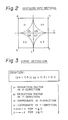
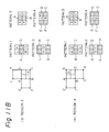
- Fig. 2 The division into sections is illustrated in Fig. 2.
- Fig. 2 the area defined by four original picture pixels A, B, C, and D is divided into eight sections G1 , G2 , G3 , G4 , G5 , G6 , G7 , and G8.
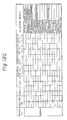
- the logic calculation can be carried out using a logic calculation table shown in Fig. 4.
- S(00), S(10), S(20), S(30), S(01), S(11), S(21), S(31), S(03), S(13), S(23), and S(33) represent white pixels of the original picture
- S(02), S(12), S(22), and S(32) represent black pixels of the original picture
- R(00), R(10), R(20), R(30), R(01), R(11), R(21), R(02), R(12), R(22), and R(22) represent pixels of the reduced picture.
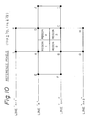
- Fig. 6 a distribution of original picture pixels with respect to reduced picture pixels is shown.
- X0 represents the X-coordinate of the preceding reduced picture pixel R(10)
- X1 represents the X-coordinate of the present reduced picture pixel R(11)
- X2 represents the X-coordinate of the subsequent reduced picture pixel R(12).
- xshift0 represents the number of original picture pixels between R(11) and R(10)
- xshift1 represents the number of original picture pixels between R(11) and R(12).
- Y0 represents the Y-coordinate of the preceding reduced picture pixel R(01)
- Y1 represents the Y-coordinate of the present reduced picture pixel R(11)
- Y2 represents the Y-coordinate of the subsequent reduced picture pixel R(21).
- yshift0 represents the number of original picture pixels between R(11) and R(01)
- yshift1 represents the number of original picture pixels between R(11) and R(21).
- Fig. 7 an example of distribution of original picture pixels is shown, to illustrate the basis of the table of conditions for detecting pixels susceptible to disappearance shown in Figs. 11A to 11D.
- the pixel number xshift0 is equal to 2
- the pixel number xshift1 is equal to 1.
- the position of R(11) is in the left-hand half ("0") of the area in question.
- the pixel number yshift0 is equal to 1
- the pixel number yshift1 is equal to 2.
- the position of R(11) is in the lower half ("1") in the Y-axis direction (Fig. 8).
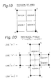
- Fig. 9 a division of the area formed by pixels A, B, C, and D into four regions 1 to4 for use in relation to the conditions for detection of pixels susceptible to disappearance is illustrated.
- Fig. 10 reference pixels for use in relation to the conditions for detection of pixels susceptible to disappearance are illustrated.
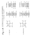
- Fig. 11 the patterns of fine line disappearance associated with regions 1 to 4 are illustrated.
- hatching denotes black portions.
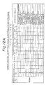
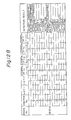
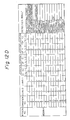
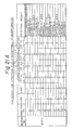
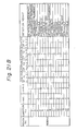
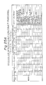
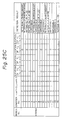
- a table of conditions for detecting pixels susceptible to disappearance will be explained with reference to Figs. 12A to 12D.
- conditions numbered 1 to 16
- columns are provided for the region number, the condition number, the number xshift1 of pixels, the number yshift1 of pixels, the present converted (reduced) picture pixel position (X1), the subsequent converted picture pixel position (X2), the present converted picture pixel position (Y1), the subsequent converted picture pixel position (Y2), and the determination of the fine line susceptible to disappearance.
- the table of Figs. 12A to 12D should be interpreted in relation with Figs. 6 to 11.
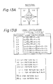
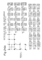
- Logic calculation tables for the calculation in the monochrome calculation circuit of the apparatus for carrying out this process according to an embodiment of the present invention shown in Fig. 14, are shown in Fig. 13B.
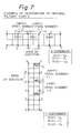
- FIG. 14A An apparatus for carrying out a process of reducing a picture according to an embodiment of the present invention is shown in Figs. 14A and 14B.
- Figure 14A is an illustration in a simplified form showing the structure for X-axis direction
- Fig. 14B is an illustration in a more detailed form showing the structure for X- and Y-axis directions.
- the apparatus of Figs. 14A and 14B is of the high speed projection method type and uses a division of 8 sections.
- a reduction factor of p where 1 > p ⁇ 1/2, for example, is used.
- the apparatus of Fig. 14A includes a pixel data input unit 1 having a shift register 11 and a shift register 12, a control unit 3 having a line disappearance susceptibility data generation portion 31 and a region discrimination portion 32, and a logic calculation circuit 4.
- the shift register 11 receives a sequence of signals of original picture pixels of an upper line of an original picture pixel group, and holds the received signal sequence by a shifting operation.
- the shift register 11 receives a sequence of signals of original picture pixels of a lower line of an original picture pixel group, and holds the received signal sequence by a shifting operation.
- Elements I, E, A, D, H, L and elements K, G, C, B, F, J of the shift registers 11 and 12 correspond to positions of original picture pixels I, E, A, D, H, L, J, F, B, C, G, and K shown in Fig. 15.
- control unit 3 the data of lines susceptible to disappearance is generated and the regions are discriminated based on the reduction factors p and q.
- control unit 2 The operation of the control unit 2 is carried out in accordance with the tables of Figs. 12A to 12D showing the condition for detecting the pixels susceptible to disappearance for the case where 1 > p ⁇ 1/2, and 1 > q ⁇ 1/2.
- xshift0 represents the number of original picture pixels between R11 and R10
- xshift1 represents the number of original picture pixels between R11 and R12.
- “1” indicates that the converted picture pixel position is situated in the first half (right side in X-direction, lower side in Y-direction) of the region in question
- "0” indicates that the converted picture pixel position is situated in the second half (left side in X-direction, upper side in Y-direction) of the region in question, as will be understood from Fig. 7 and Fig. 8.
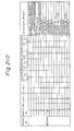
- the logic calculation is carried out in accordance with the table shown in Fig. 13B or the table shown in Fig. 13C.
- the table of Fig. 13B is for a factor of 1 > p ⁇ 1/2 and 1 > q ⁇ 1/2
- the table of Fig. 13C is for a factor of 1/2 > p ⁇ 1/3 and 1/2 > q ⁇ 1/3.
- the discrimination of regions in the region discrimination portion 32 of the control unit 3 is carried out in accordance with a discrimination based on the curve defined in Fig. 3 and shown in Fig. 2.
- the converted picture pixel R(11) is surrounded by the four adjacent original picture pixels S(11), S(21), S(22), and S(12) and the converted picture pixel R(11) belongs to range (section) G5.
- the monochrome data of the converted picture pixel R(11) is calculated in accordance with the table shown in Fig. 12A based on the information of the location of R(11), that is G5, and the information of the monochrome data of the original picture pixels.
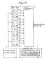
- FIG. 17 An apparatus for carrying out a process for reducing a picture according to a modified version of the above-described embodiment of the present invention is shown in Fig. 17.
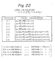
- the apparatus of Fig. 17 is of the high speed projection method type and uses the division of 4 sections.
- the reduction rate of, for example, 1 > p ⁇ 1/3 is used.
- the apparatus of Fig. 17 includes a pixel data input unit 1, a two dimensional picture storage unit 2, a control unit 3, and a monochrome data logic calculation circuit 4.
- the pixel data input unit 1 includes eight shift registers 11 to 18.
- the shift registers 11 and 12 hold data of the original picture pixels on the first line, the shift registers 13 and 14, the second line, the shift registers 15 and 16, the third line, and the shift registers 17 and 18, the fourth line.
- the control unit 3 includes a line disappearance susceptibility data generation portion 31 and a region discrimination portion 32.
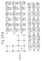
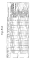
- FIG. 12A to 12D A table of logic calculations for the apparatus of Fig. 17 is shown in Fig. 22.
- FIG. 23 An assumption of reference pixels used in the apparatus of Fig. 17 is illustrated in Fig. 23.
- Basic patterns of fine line disappearance in relation with the apparatus of Fig. 17 are illustrated in Figs. 24A to 24D.
- a table of the condition for detecting disappearance of pixels to be converted as the basis of the operation of the apparatus of Fig. 17 is shown in Figs. 25A to 25D.
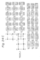
- a table of logic calculations used in the operation of the apparatus of Fig. 17 is shown in Fig. 26.
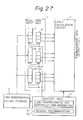
- FIG. 27 An apparatus for carrying out a process for reducing a picture according to another embodiment of the present invention is shown in Fig. 27.
- the apparatus of Fig. 27 is of the selective processing conversion method type and uses the division of 4 sections.
- a reduction factor of p where for example 1 > p ⁇ 1/3, is used.
- the apparatus of Fig. 27 includes a pixel data input unit 1, a two dimensional picture storage 2, a control unit 3, and a monochrome data logic calculation circuit 4.
- the pixel data input unit 1 includes shift registers 11 to 16, the shift registers 11 and 12 hold the data of the original picture pixels in the first line, the shift registers 13 and 14, the second line, and the shift registers 15 and 16, the third line.
- the control unit 3 includes a line disappearance susceptibility data generation portion 31 and a region discrimination portion 32.
- the data produced relating to a line susceptible to disappearance further includes; affirmations, with regard to the Y-axis direction, of an inequality in that the preceding pixel position coordinate (y0) of the converted picture is greater than a reference position coordinate (y ref), an inequality in that the present pixel position coordinate (y1) is greater than a reference position coordinate (y ref), and an inequality in that the subsequent pixel position coordinate (y2) is greater than a reference position coordinate (y ref); and the number of original picture pixels between the present pixel position coordinate (y1) and the preceding pixel position coordinate (y0) or the subsequent pixel position coordinate (y2).
- an affirmation, with regard to the X-axis direction, of an inequality in that the present pixel position coordinate (x1) of the converted picture is greater than a reference position coordinate (x ref), and an affirmation, with regard to the Y-axis direction, of an inequality in that the present pixel position coordinate (y1) of the converted picture is greater than a reference position coordinate (y ref), are used.
- a logic calculation to preserve a fine line based on data relating to a line susceptible to disappearance is added to a logic calculation step for combination with the most adjacent pixel of the original picture or the pixels close to the most adjacent pixel of original picture.
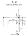
- FIG. 6 The distribution of original picture pixels with respect to reduced picture pixels used in the apparatus of Fig. 27 is illustrated in Fig. 6.
- a method of division into regions used in the apparatus of Fig. 27 is illustrated in Fig. 29.
- An assumption of reference pixels used in the apparatus of Fig. 27 is illustrated in Fig. 30.
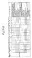
- a table of the condition for detecting disappearance of pixels to be converted as the basis of the operation of the apparatus is shown in Figs. 12A to 12D, and a table of the logic calculation used in the operation of the apparatus of Fig. 27 is shown in Fig. 32.
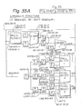
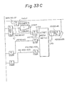
- FIG. 33A, 33B and 33C An example of the structures of an apparatus for carrying out a process for reducing a picture according to an embodiment of the present invention is shown in Figs. 33A, 33B and 33C.
- FIG. 34A, 34B, and 34C An example of the operation of an apparatus for carrying out a process for reducing a picture according to an embodiment of the present invention is shown in Figs. 34A, 34B, and 34C.
- the multiplexer-1, the adder-1, and the register R111 and R1 constitute an Xi coordinate calculation portion
- the pixel selection circuits-1, -2, and -3 the registers R11, R21 to R23, R31 to R33, R41 to 43, R51 to 53, and R134 constitute an original picture pixel input portion
- the subtracter-1, and the register R122, R132, R133, and R142 constitute a disappearance susceptibility data generation portion
- the pattern group decision circuit and the registers R131, R132, R141, R142, and R151 constitute a pattern group decision portion
- the pattern detection circuit and the registers R152 and R153 constitute a pattern detection portion
- the comparator-1 and the registers R3, R161, and R171 constitute a region division decision portion
- the logic arithmetic circuit and the registers R171, R172, and R61, and the shift register SR1 constitute a logic arithmetic portion.
- the registers R1 to R3 are applied to an operation in units of one line
- the registers R11, R21 to R23, R31 to R33, R41 to R43, R51 to R53, and R61 are applied to an operation in units of one word, i.e., 16 pixels
- the registers R111, R121, R122, R131 to R134 R141 to R143, R151 to R153, R161 to R164, and R171 to R173 are applied to an operation in units of one pixel.
- a selection of 4 reference pixels is carried out for detecting a line susceptible to disappearance from among 19 pixels, i.e., 16 pixels plus 3 adjacent pixels per 3 lines in question.
- a decision concerning fine line pattern disappearance is carried out by using the table of conditions of detection of disappearance.
- a decision of whether or not a fine line pattern susceptible to disappearance appears in the reference pixel group is made.
- the monochrome data of the converted picture pixel is decided from the decision of a region, the detection of a fine line pattern, and the data of the reference pixel.
- Fig. 34A illustrating a 2/3 reduction
- Fig. 34B illustrating standard pixel for the reference pixel group in correspondence with the timings
- Fig. 34C illustrating the timings.
Landscapes
- Engineering & Computer Science (AREA)
- Multimedia (AREA)
- Signal Processing (AREA)
- Image Processing (AREA)
- Editing Of Facsimile Originals (AREA)
Applications Claiming Priority (4)
| Application Number | Priority Date | Filing Date | Title |
|---|---|---|---|
| JP63802/88 | 1988-03-18 | ||
| JP63063802A JP2588742B2 (ja) | 1988-03-18 | 1988-03-18 | 画像縮小装置及び方法 |
| JP213673/88 | 1988-08-30 | ||
| JP63213673A JP2588758B2 (ja) | 1988-08-30 | 1988-08-30 | 画像縮小装置及び方法 |
Publications (3)
| Publication Number | Publication Date |
|---|---|
| EP0333496A2 true EP0333496A2 (de) | 1989-09-20 |
| EP0333496A3 EP0333496A3 (de) | 1991-12-18 |
| EP0333496B1 EP0333496B1 (de) | 1995-06-21 |
Family
ID=26404924
Family Applications (1)
| Application Number | Title | Priority Date | Filing Date |
|---|---|---|---|
| EP89302645A Expired - Lifetime EP0333496B1 (de) | 1988-03-18 | 1989-03-17 | Vermeiden des Verschwindens von dünnen Linien in Bildreduzierverfahren |
Country Status (5)
| Country | Link |
|---|---|
| US (1) | US4930021A (de) |
| EP (1) | EP0333496B1 (de) |
| KR (1) | KR920008904B1 (de) |
| CA (1) | CA1306052C (de) |
| DE (1) | DE68923110T2 (de) |
Cited By (3)
| Publication number | Priority date | Publication date | Assignee | Title |
|---|---|---|---|---|
| EP0376679A3 (de) * | 1988-12-28 | 1992-01-22 | Canon Kabushiki Kaisha | Bildkodiervorrichtung und Bildkodierverfahren |
| EP0401058A3 (de) * | 1989-02-23 | 1992-10-28 | Nippon Telegraph And Telephone Corporation | Binäres Bildreduzierungsverfahren |
| EP0576298A3 (de) * | 1992-06-26 | 1994-04-20 | Canon Kk |
Families Citing this family (16)
| Publication number | Priority date | Publication date | Assignee | Title |
|---|---|---|---|---|
| US5083216A (en) * | 1988-12-27 | 1992-01-21 | Kabushiki Kaisha Toshiba | Image forming apparatus for forming an image according to magnification |
| JPH02217897A (ja) * | 1989-02-20 | 1990-08-30 | Hitachi Ltd | 画素密度変換方式 |
| JP2787832B2 (ja) * | 1989-06-30 | 1998-08-20 | キヤノン株式会社 | 画像縮小方法 |
| JP2767933B2 (ja) * | 1989-11-14 | 1998-06-25 | ソニー株式会社 | 画素数変換回路 |
| DE69121439T2 (de) * | 1990-03-19 | 1997-01-09 | Canon Kk | Verfahren und Gerät zur Bildverarbeitung |
| US5680225A (en) * | 1991-02-14 | 1997-10-21 | Canon Kabushiki Kaisha | Image reduction with fine-line protection |
| JP2625045B2 (ja) * | 1991-04-05 | 1997-06-25 | 大日本スクリーン製造株式会社 | 画像処理装置 |
| JP2771712B2 (ja) * | 1991-06-10 | 1998-07-02 | キヤノン株式会社 | 画素密度変換装置 |
| DE69232403T2 (de) * | 1991-08-06 | 2002-08-22 | Canon K.K., Tokio/Tokyo | Dreidimensionales Modellverarbeitungsverfahren und -gerät |
| JPH05268462A (ja) * | 1992-03-19 | 1993-10-15 | Mitsubishi Electric Corp | 画像処理装置 |
| JPH05334427A (ja) * | 1992-06-03 | 1993-12-17 | Hitachi Ltd | 画像の拡大縮小方法 |
| US5838838A (en) * | 1996-07-19 | 1998-11-17 | Hewlett-Packard Company | Down-scaling technique for bi-level images |
| JP3303818B2 (ja) * | 1999-01-27 | 2002-07-22 | 日本電気株式会社 | 映像表示方法、及び映像表示システム |
| SG92628A1 (en) | 1999-02-13 | 2002-11-19 | Newstakes Inc | A method and apparatus for converting video to multiple mark-up-language presentations |
| TWI510075B (zh) * | 2011-11-25 | 2015-11-21 | Novatek Microelectronics Corp | 偵測產品圖案消失的方法與電路 |
| JP5990217B2 (ja) * | 2014-05-21 | 2016-09-07 | キヤノン株式会社 | 画像処理装置、画像形成装置、およびそれらの制御方法 |
Family Cites Families (5)
| Publication number | Priority date | Publication date | Assignee | Title |
|---|---|---|---|---|
| US4275450A (en) * | 1979-08-01 | 1981-06-23 | Xerox Corporation | Magnification/demagnification apparatus and method |
| JPS60183883A (ja) * | 1984-03-02 | 1985-09-19 | Canon Inc | 画像処理装置 |
| JPH0685556B2 (ja) * | 1984-03-30 | 1994-10-26 | 大日本スクリ−ン製造株式会社 | 画像走査記録装置における倍率変換方法 |
| JPS60218974A (ja) * | 1984-04-16 | 1985-11-01 | Canon Inc | フアクシミリ装置 |
| DE3545157A1 (de) * | 1985-12-20 | 1987-06-25 | Philips Patentverwaltung | Verfahren und schaltungsanordnung zur aufloesungsumwandlung von binaeren pseudo-halbtonbildern |
-
1989
- 1989-03-16 CA CA000593928A patent/CA1306052C/en not_active Expired - Lifetime
- 1989-03-17 DE DE68923110T patent/DE68923110T2/de not_active Expired - Fee Related
- 1989-03-17 EP EP89302645A patent/EP0333496B1/de not_active Expired - Lifetime
- 1989-03-18 KR KR1019890003372A patent/KR920008904B1/ko not_active Expired
- 1989-03-20 US US07/325,912 patent/US4930021A/en not_active Expired - Lifetime
Cited By (4)
| Publication number | Priority date | Publication date | Assignee | Title |
|---|---|---|---|---|
| EP0376679A3 (de) * | 1988-12-28 | 1992-01-22 | Canon Kabushiki Kaisha | Bildkodiervorrichtung und Bildkodierverfahren |
| EP0401058A3 (de) * | 1989-02-23 | 1992-10-28 | Nippon Telegraph And Telephone Corporation | Binäres Bildreduzierungsverfahren |
| EP0576298A3 (de) * | 1992-06-26 | 1994-04-20 | Canon Kk | |
| US5579405A (en) * | 1992-06-26 | 1996-11-26 | Canon Kabushiki Kaisha | Method and apparatus for contour vector image processing |
Also Published As
| Publication number | Publication date |
|---|---|
| KR920008904B1 (ko) | 1992-10-10 |
| DE68923110D1 (de) | 1995-07-27 |
| US4930021A (en) | 1990-05-29 |
| EP0333496B1 (de) | 1995-06-21 |
| KR890015563A (ko) | 1989-10-30 |
| DE68923110T2 (de) | 1995-10-26 |
| CA1306052C (en) | 1992-08-04 |
| EP0333496A3 (de) | 1991-12-18 |
Similar Documents
| Publication | Publication Date | Title |
|---|---|---|
| EP0333496A2 (de) | Vermeiden des Verschwindens von dünnen Linien in Bildreduzierverfahren | |
| KR920009611B1 (ko) | 화소 신호의 상관판정 및 보간 데이타 작성장치 | |
| CA1335794C (en) | Process and apparatus for image magnification | |
| US4259694A (en) | Electronic rescreen technique for halftone pictures | |
| EP0696132B1 (de) | Fehlerdiffusionsverfahren hoher Adressierbarkeit | |
| EP0201674B1 (de) | Verfahren zur Reproduktion digitaler Bilder mit Mehrfachtönung mittels eines Doppeltönungsdruckers mit fester Punktgrösse | |
| US5526476A (en) | Method and apparatus for generating character patterns expressed by coordinates of a coordinate system | |
| HK13196A (en) | Process for correcting transmission errors | |
| US5278671A (en) | Image processing apparatus with correction of diffusion errors of overlapping dots | |
| GB2224906A (en) | Image signal dot region discrimination | |
| US5638188A (en) | Image processing method and apparatus with storing and selecting of dot patterns | |
| US4903142A (en) | Apparatus for processing halftone image | |
| KR900008269B1 (ko) | 평활장치 | |
| US5010497A (en) | Image information recorder having a resolution density transformation device | |
| JP3484438B2 (ja) | ハーフトーン画像を表示する方法 | |
| GB2150797A (en) | Graphic display system | |
| EP0631430A2 (de) | Farbbildverarbeitungsgerät geeignet zum Unterdrücken von Moire | |
| EP0454088B1 (de) | Bildverarbeitungsvorrichtung | |
| US5606656A (en) | Image data processing unit for forming a plurality of identical images in a single output image area | |
| GB2249910A (en) | Method of making a half-tone reproduction of an image | |
| JP2588742B2 (ja) | 画像縮小装置及び方法 | |
| JP4071847B2 (ja) | 画像処理装置 | |
| US7079699B2 (en) | Multi-valued image conversion device, multi-valued image conversion program, and multi-valued image conversion method | |
| JP3392800B2 (ja) | 補間方法及びその装置並びに記録媒体 | |
| JP2613080B2 (ja) | 画像拡大装置及び方法 |
Legal Events
| Date | Code | Title | Description |
|---|---|---|---|
| PUAI | Public reference made under article 153(3) epc to a published international application that has entered the european phase |
Free format text: ORIGINAL CODE: 0009012 |
|
| AK | Designated contracting states |
Kind code of ref document: A2 Designated state(s): DE FR GB |
|
| PUAL | Search report despatched |
Free format text: ORIGINAL CODE: 0009013 |
|
| AK | Designated contracting states |
Kind code of ref document: A3 Designated state(s): DE FR GB |
|
| 17P | Request for examination filed |
Effective date: 19920316 |
|
| 17Q | First examination report despatched |
Effective date: 19930927 |
|
| GRAA | (expected) grant |
Free format text: ORIGINAL CODE: 0009210 |
|
| AK | Designated contracting states |
Kind code of ref document: B1 Designated state(s): DE FR GB |
|
| REF | Corresponds to: |
Ref document number: 68923110 Country of ref document: DE Date of ref document: 19950727 |
|
| ET | Fr: translation filed | ||
| PLBE | No opposition filed within time limit |
Free format text: ORIGINAL CODE: 0009261 |
|
| STAA | Information on the status of an ep patent application or granted ep patent |
Free format text: STATUS: NO OPPOSITION FILED WITHIN TIME LIMIT |
|
| 26N | No opposition filed | ||
| PGFP | Annual fee paid to national office [announced via postgrant information from national office to epo] |
Ref country code: DE Payment date: 20010312 Year of fee payment: 13 |
|
| PGFP | Annual fee paid to national office [announced via postgrant information from national office to epo] |
Ref country code: FR Payment date: 20010313 Year of fee payment: 13 |
|
| PGFP | Annual fee paid to national office [announced via postgrant information from national office to epo] |
Ref country code: GB Payment date: 20010314 Year of fee payment: 13 |
|
| REG | Reference to a national code |
Ref country code: GB Ref legal event code: IF02 |
|
| PG25 | Lapsed in a contracting state [announced via postgrant information from national office to epo] |
Ref country code: GB Free format text: LAPSE BECAUSE OF NON-PAYMENT OF DUE FEES Effective date: 20020317 |
|
| PG25 | Lapsed in a contracting state [announced via postgrant information from national office to epo] |
Ref country code: DE Free format text: LAPSE BECAUSE OF NON-PAYMENT OF DUE FEES Effective date: 20021001 |
|
| GBPC | Gb: european patent ceased through non-payment of renewal fee |
Effective date: 20020317 |
|
| PG25 | Lapsed in a contracting state [announced via postgrant information from national office to epo] |
Ref country code: FR Free format text: LAPSE BECAUSE OF NON-PAYMENT OF DUE FEES Effective date: 20021129 |
|
| REG | Reference to a national code |
Ref country code: FR Ref legal event code: ST |