EP0327029A2 - Dispositif de conduite de tir - Google Patents
Dispositif de conduite de tir Download PDFInfo
- Publication number
- EP0327029A2 EP0327029A2 EP89101648A EP89101648A EP0327029A2 EP 0327029 A2 EP0327029 A2 EP 0327029A2 EP 89101648 A EP89101648 A EP 89101648A EP 89101648 A EP89101648 A EP 89101648A EP 0327029 A2 EP0327029 A2 EP 0327029A2
- Authority
- EP
- European Patent Office
- Prior art keywords
- frame
- control
- interface
- slide
- fire control
- Prior art date
- Legal status (The legal status is an assumption and is not a legal conclusion. Google has not performed a legal analysis and makes no representation as to the accuracy of the status listed.)
- Withdrawn
Links
Images


Classifications
-
- F—MECHANICAL ENGINEERING; LIGHTING; HEATING; WEAPONS; BLASTING
- F41—WEAPONS
- F41G—WEAPON SIGHTS; AIMING
- F41G5/00—Elevating or traversing control systems for guns
- F41G5/14—Elevating or traversing control systems for guns for vehicle-borne guns
-
- F—MECHANICAL ENGINEERING; LIGHTING; HEATING; WEAPONS; BLASTING
- F41—WEAPONS
- F41G—WEAPON SIGHTS; AIMING
- F41G3/00—Aiming or laying means
- F41G3/04—Aiming or laying means for dispersing fire from a battery ; for controlling spread of shots; for coordinating fire from spaced weapons
Definitions
- the invention relates to a fire control system with at least two operator stations. These operator stations can be that of the gunner, that of the commander and, if applicable, that of the loader. Fire control systems of this type are primarily common in appropriately armed land vehicles, even if an appropriate use of the fire control system appears conceivable in air and water vehicles.
- connection unit of the fire control system is assigned an electronics unit specific for this connection unit.
- the gyro stabilization for the main weapon is controlled by a special electronics unit, as is the gyro stabilization of the rifle target's rangefinder and, if necessary, the gyro stabilization of the commander's telescope.
- a special electronics unit is again provided for the ballistic fire control calculation. Disadvantageous This concept is based on the large number of required components of the electronic units of the fire control system at the various operator stations that differ in terms of structure and function. This results in logistical problems as well as maintenance problems and comparatively little flexibility with regard to changing the fire control system.
- the object of the invention is to provide a largely standardized fire control system in which the most important functions are still provided even if individual system parts fail.
- a fire control system which achieves this object and has at least two operator stations - one slide-in frame with electronic assemblies per control station, at least one functional assembly per frame, in particular a stabilization assembly for the main weapon or a target device or main supply assembly, - at least one interface and control module per frame, - a bus line to which the interfaces and control modules of all frames are connected, at least some of the functional assemblies being formed by essentially identical standard assemblies, wherein the overall control of the fire control system is preferably carried out by a predetermined first interface and control module and, if it fails, a predetermined second interface and control module, and preferably also if the bus line fails, the interface and control module of the slide-in frame assigned to the main weapon is the automatic one Control of the modules of this rack.
- connection units to be connected to the fire control system differ, even if they perform related functions.
- the gyro stabilization units used for the targeting devices and weapons are often different on the one hand in structure and, on the other hand, also differ in their reaction to changes in the position of the vehicle due to the greatly differing masses involved. Accordingly, the assembly group responsible for the gyro stabilization device can only work correctly if it is provided with the adaptation parameters of the connected connection unit required for the correct control or regulation of the tracking drives.
- the standard assembly is designed with a data record memory, in which adaptation parameter data records are stored for all of the possible differently equipped operating stations, and that each insertion frame is provided with a data record selection device, which causes the selection of the respective data record.
- the standard groups with the same hardware are also equipped with the same software, with the possible adjustment parameter data records being stored from the outset.
- the required selection is made by the slide-in frame.
- the slide-in frame is provided with a spatial code, in particular a pin code, which causes the selection of the respective data record when the standard assembly is inserted.
- the standard main group is provided with a self-optimizing, adaptive control circuit for automatic adaptation to the respectively connected devices.
- the standard module therefore "learns" at the beginning of operation from the reactions of the connected connection unit in an optimization process which adaptation parameters are to be used.
- one adaptation module is provided per frame with a data record memory for the adaptation parameters relevant for this frame.
- the standard modules only receive the relevant adaptation parameter set on the spot in the slide-in frame from the adaptation module. In extreme cases, this is the only one in each case Slide-in frame, ie assembly adapted to the respective connection unit of the slide-in frame.
- one of the frames prefferably be provided with a main data memory in which adaptation parameter data records of all the insertion frames are stored, and for the interface and control module of this frame to transmit the respective adaptation parameter data records via the bus to the individual insertion frames initiated (initialization).
- This solution saves the adaptation module or the data set selection device for the individual slide-in frames.
- program memories are also provided in the central memory with the computer programs assigned to the individual standard modules, and that the associated interface and control module causes the transfer of these programs to the individual standard modules (initialization).
- the overall control of the system and the interface and control module can advantageously take on at least one of the following functions: bus control, operating mode selection, e.g. priority control during operation by the commander, fire control calculation (ballistic calculation if necessary taking into account signals from connected sensors such as vertical sensor, temperature sensor, cross wind, etc .; guiding and tracking target devices and weapon systems; fault detection and fault location within the fire control system; system adjustment, in particular parallelism of gyro axes or the like.
- the fire control system to be described in its various versions is characterized by a simple modular structure with a high degree of standardization. It requires little testing effort, easy error localization and a high degree of flexibility. As a result, additional devices or sensors can be easily connected, and individual devices or sensors can also be replaced with successor models. As the exemplary embodiments will show, the fire control system according to the invention can be used in a wide variety of weapon carriers without major changes.
- the electronic assemblies of the fire control system are connected to a bus line, although it has proven to be particularly advantageous not to connect all the assemblies individually to the bus line, but to combine several assemblies, each assigned to an operator station, in a slide-in frame and via one to connect the only bus terminal to the bus line. Since each operating station is assigned a slide-in frame with largely complete electronics, there is the possibility of island operation if communication with the other slide-in frames is no longer possible, for example due to a failure of the Bus line or parts of other slide-in frames. Finally, the decentralized arrangement of the electronics is also advantageous with regard to the mostly limited installation space, since there is more space available for small-volume modules at the respective operator stations than at a central location for a correspondingly large overall system.
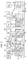
- a slide-in frame 10, 12, 14 is arranged at three operating stations, into which the electronic assemblies required there are inserted.
- the slide-in frame 10 is located in the area of the operating position of the gunner, the slide-in frame 12 in the area of the commandant's operating space and the slide-in frame 14 at any other location, for example in the vicinity of the radio.
- FLA electronics 1 F your l eit a nLocated
- withdrawable frame three modules are inserted 16,18 and 20th
- the assembly 16 is with a HW rod. referred to what is H AuPt w Monkey Bar ilmaschine.
- the module is with interfaces u.
- Control referred which stands for the interface and control module
- the module 20 is finally indicated with ZG-EL, which stands for Z iel g erät- E lectronic.
- the interface and control module 18 takes over the interface adaptation of all modules in the rack 10 to the respectively connected connection units.
- a drive unit 22 side and height of the main weapon HW page / height in Fig. 1 hereinafter
- the latter is provided with a Z iel g et up instrument SE sch ützen (ZGRisch 28) is integrated, which is in turn connected via a rigid mechanical link 30 with the main weapon.
- ZGRisch 28 Z iel g et up instrument SE sch ützen
- the thermal imaging unit 26 can be equipped with a separate one Be connected Slee W b ild g edorf- El ektronikatti (WBGEL 32) which is integrated in general in the thermal imaging device unit 26th
- WBGEL 32 Be connected Slee W b ild g erät- El ektronikatti
- the unit 32 can also be integrated into the frame 10.
- the plug-in frame 10 and its assemblies 16, 18, 20 are connected to a bus line 36 (connecting line 38) via a bus terminal 34 denoted by T.
- the slide-in frame which is designated by FLA electronics 2, is located at the operator's control station.
- An interface and control module 40 and a target device tracking module 42 are inserted therein.
- the module 40 serves, among other things, to adapt the interfaces of the modules of the slide-in frame 12 with the connected connection units.
- These are one or more fire control sensor units 44 (vertical sensor, powder temperature sensor, cross wind sensor, or the like.),
- An integrated control and display unit 46 if necessary, a corresponding integrated control and display unit 48 for a L ade s protect (LS) and a target device unit 50.
- the target device tracking unit 42 then ensures the actuation of corresponding tracking drives in the connection unit 50.
- the commander target device is to be of a position-stabilized design, in particular in the form of a gyro-stabilized panoramic periscope, see above
- a corresponding aiming device stabilizing unit 42a is to be inserted into the insertion frame 12, as is the case with the embodiment according to FIG. 2.
- the corresponding insertion in the insertion frame 12 is omitted.
- the integrated operating and display unit of the charging contactor 48 can be connected to the interface and control module 40.
- the interface and control module 40 also serves as the central unit for overall control of the system. In addition to the ballistic calculations, it provides e.g. for the operating mode selection, which enables either the gunner or the commander, if necessary with priority control in favor of the commander, to issue the corresponding fire commands.
- the assembly 40 causes via the bus 36 and the assemblies of the slide-in frame 10, which are in connection with the connection unit 22 for adjusting the height and side of the main weapon, that the main weapon is guided or tracked accordingly.
- the assembly 10 can also be used for fault detection and fault localization of the overall system and for system adjustment, for example if several stabilizing gyros are used, the axes of which are to be aligned parallel to one another.
- an interface and control module 52 as well as a main distributor module 54.
- the module 52 in turn provides the interface adaptation to the connected connection units, here to a radio adapter unit 56 designated AEF connected control receiver unit 58 (radio for data radio).
- AEF connected control receiver unit 58 radio for data radio.
- a dashed connecting line or outline of the respective block of the block diagram indicates that this line or the block can also be omitted. Accordingly, the connection for data radio omitted.
- the assembly 54 designated HV (main distributor), is used for the central power supply of all fire control assemblies, including device protection. Lights and other on-board electrical equipment can also be connected.
- HV main distributor
- the bus line 36 can be connected via a slip ring 60 to a connecting bus line 64 within the vehicle body or armored tank.
- An assembly 68 which provides the data connection to the chassis can in turn be connected to this bus line 64 within a corresponding slide-in frame 66.
- the interface and control module 40 responsible for the overall control can also carry out a direct check of the on-board electrical system.
- both the aiming device unit 28a of the gunner and the targeting device unit 50a of the commander are each equipped with mutually independent stabilizing devices, which in turn have a corresponding aiming device stabilizing assembly 20a or 42a in the insertion frame 10 or 12 connected to the corresponding position stabilization of the respective target device even at full speed.
- an auxiliary rifle scope 70 may be rigidly connected to the main weapon.
- an automatic loader 72 is now provided, which is connected to a corresponding module 74, referred to as "auto loader", in the slide-in frame 14 via the interface and control module 52.
- FIG. 3 is a fire control system for a rifle combat vehicle. It is assumed that at least one primarily stabilized machine gun is provided for the weapon system. A fire control system is no longer required for combat vehicles with even simpler armament.
- the aiming units 28 and 50 for the gunner and the commander are mechanically coupled to the main weapon. Since in such vehicles the weapon turrets have small spatial dimensions and thus the installation space is further restricted, the electronic assemblies to be inserted concentrate on the slide-in frame 10 (FLA electronics 1) and the slide-in frame 14 (FLA electronics 3).
- the slide-in frame 10 there is in turn the main weapon stabilization assembly 16, the interface and control assembly 18 and in this case a thermal imaging device assembly 32a, which replaces the separate unit 32 in FIGS. 1 and 2.
- the slide-in frame 12 which is not required in the normal version can be provided. While in the normal version the integrated operating and display unit 46 intended for the commander is connected to the slide-in frame 10, this can alternatively also be connected to the slide-in frame 12.
- the fire control systems described have a high level of reliability. If, for example, the overall control of the system and the interface and control module 40 fails, its function is immediately taken over by the interface and control module 18. also the full data bus control, so that the control of the FLA electronics 3 with the automatic loader is still possible by the gunner without restriction. Only the commander is no longer able to use the main weapon himself. Finally, if the bus line 36 fails, FLA electronics 1 can still be fully functional by itself, even if the automatic charger would have to be triggered manually in this case.
- Hardware-equivalent modules have the same hardware structure, e.g. all interface and control assemblies 18, 40, 52 and all stabilization assemblies 16, 20a and 42a.
- the required adjustment parameter data records are supplied to the modules in the manner already described above.
- the groups of plug-in frames 10, 12, 14 are connected to the bus 36 in each case via the only bus terminal 80 which is controlled by the respective interface and control module. Furthermore, it should be noted that further units, such as further sensors for ballistic parameters or the like, can also be connected to the bus 36 without further notice.
- a fire control system with at least two control stations comprises a slide-in frame with electronic modules per control station, at least one function module as well as an interface and control module and a bus line per frame, at least some of the function modules being of essentially identical standard Modules are formed, and wherein the overall control of the fire control system is carried out by a predetermined first interface and control module and, if it fails, by a predetermined second interface and control module, and finally, if the bus line fails, the interface and control Assembly of the slide-in frame assigned to the main weapon carries out the automatic control of the assemblies of this slide-in frame.
Applications Claiming Priority (2)
| Application Number | Priority Date | Filing Date | Title |
|---|---|---|---|
| DE3802894 | 1988-02-01 | ||
| DE19883802894 DE3802894A1 (de) | 1988-02-01 | 1988-02-01 | Feuerleitanlage |
Publications (2)
| Publication Number | Publication Date |
|---|---|
| EP0327029A2 true EP0327029A2 (fr) | 1989-08-09 |
| EP0327029A3 EP0327029A3 (fr) | 1990-12-27 |
Family
ID=6346382
Family Applications (1)
| Application Number | Title | Priority Date | Filing Date |
|---|---|---|---|
| EP19890101648 Withdrawn EP0327029A3 (fr) | 1988-02-01 | 1989-01-31 | Dispositif de conduite de tir |
Country Status (2)
| Country | Link |
|---|---|
| EP (1) | EP0327029A3 (fr) |
| DE (1) | DE3802894A1 (fr) |
Cited By (4)
| Publication number | Priority date | Publication date | Assignee | Title |
|---|---|---|---|---|
| EP0405732A2 (fr) * | 1989-06-07 | 1991-01-02 | The Marconi Company Limited | Multiprocesseur de traitement numérique du signal |
| EP0852326A1 (fr) * | 1996-12-09 | 1998-07-08 | Oerlikon-Contraves AG | Batterie d'armes, en particulier pour unités de tir anti-aériennes |
| FR2873221A1 (fr) * | 2004-07-16 | 2006-01-20 | Dcn Sa | Systeme de traitement et de gestion des informations tactiques d'evolution d'une plateforme de combat |
| WO2006126966A2 (fr) * | 2005-05-25 | 2006-11-30 | Bae Systems Bofors Ab | Systeme et procede permettant d'afficher une cible |
Families Citing this family (1)
| Publication number | Priority date | Publication date | Assignee | Title |
|---|---|---|---|---|
| DE19716198C2 (de) * | 1997-04-18 | 1999-11-04 | Rheinmetall W & M Gmbh | Waffenanlage |
Citations (5)
| Publication number | Priority date | Publication date | Assignee | Title |
|---|---|---|---|---|
| GB2136097A (en) * | 1979-03-30 | 1984-09-12 | Siemens Ag | Target-tracking Interception Control Systems |
| US4634110A (en) * | 1983-07-28 | 1987-01-06 | Harris Corporation | Fault detection and redundancy management system |
| US4639856A (en) * | 1983-11-04 | 1987-01-27 | International Business Machines Corporation | Dual stream processor apparatus |
| FR2597226A1 (fr) * | 1986-04-09 | 1987-10-16 | Messerschmitt Boelkow Blohm | Calculateur de guidage pour une installation de lancement |
| EP0249679A2 (fr) * | 1986-04-18 | 1987-12-23 | MaK System Gesellschaft mbH | Dispositif de conduite de tir pour système d'armes d'un véhicule blindé |
-
1988
- 1988-02-01 DE DE19883802894 patent/DE3802894A1/de not_active Withdrawn
-
1989
- 1989-01-31 EP EP19890101648 patent/EP0327029A3/fr not_active Withdrawn
Patent Citations (5)
| Publication number | Priority date | Publication date | Assignee | Title |
|---|---|---|---|---|
| GB2136097A (en) * | 1979-03-30 | 1984-09-12 | Siemens Ag | Target-tracking Interception Control Systems |
| US4634110A (en) * | 1983-07-28 | 1987-01-06 | Harris Corporation | Fault detection and redundancy management system |
| US4639856A (en) * | 1983-11-04 | 1987-01-27 | International Business Machines Corporation | Dual stream processor apparatus |
| FR2597226A1 (fr) * | 1986-04-09 | 1987-10-16 | Messerschmitt Boelkow Blohm | Calculateur de guidage pour une installation de lancement |
| EP0249679A2 (fr) * | 1986-04-18 | 1987-12-23 | MaK System Gesellschaft mbH | Dispositif de conduite de tir pour système d'armes d'un véhicule blindé |
Non-Patent Citations (1)
| Title |
|---|
| PROCEEDINGS OF THE IEEE, NAECON, 1986, Band 1, Seiten 119-124; G. ELENGICAL et al.: "Capability assessment in airborne platforms" * |
Cited By (9)
| Publication number | Priority date | Publication date | Assignee | Title |
|---|---|---|---|---|
| EP0405732A2 (fr) * | 1989-06-07 | 1991-01-02 | The Marconi Company Limited | Multiprocesseur de traitement numérique du signal |
| EP0405732A3 (en) * | 1989-06-07 | 1993-02-03 | The Marconi Company Limited | Digital signal multiprocessor |
| EP0852326A1 (fr) * | 1996-12-09 | 1998-07-08 | Oerlikon-Contraves AG | Batterie d'armes, en particulier pour unités de tir anti-aériennes |
| FR2873221A1 (fr) * | 2004-07-16 | 2006-01-20 | Dcn Sa | Systeme de traitement et de gestion des informations tactiques d'evolution d'une plateforme de combat |
| WO2006126966A2 (fr) * | 2005-05-25 | 2006-11-30 | Bae Systems Bofors Ab | Systeme et procede permettant d'afficher une cible |
| WO2006126966A3 (fr) * | 2005-05-25 | 2007-09-20 | Bae Systems Bofors Ab | Systeme et procede permettant d'afficher une cible |
| GB2440882A (en) * | 2005-05-25 | 2008-02-13 | Bae Systems Bofors Ab | System and process for displaying a target |
| GB2440882B (en) * | 2005-05-25 | 2008-11-19 | Bae Systems Bofors Ab | System and process for displaying a target |
| US8624781B2 (en) | 2005-05-25 | 2014-01-07 | Bae Systems Bofors Ab | System and process for displaying a target |
Also Published As
| Publication number | Publication date |
|---|---|
| EP0327029A3 (fr) | 1990-12-27 |
| DE3802894A1 (de) | 1989-08-10 |
Similar Documents
| Publication | Publication Date | Title |
|---|---|---|
| EP1495280B1 (fr) | Vehicule de combat, en particulier vehicule blinde de combat d'infanterie | |
| EP1061323B2 (fr) | Véhicule blindé pour le transport de soldats | |
| EP1752376A2 (fr) | Aéronef, en particulier aéronef téléguidé, avec au moins une soute d'armes | |
| EP1371931B1 (fr) | Procédé et dispositif pour déterminer une erreur angulaire et utilisation de ce dispositif | |
| DE3122384A1 (de) | Geraet mit mehreren ausbildungsplaetzen zur ausbildung von richtschuetzen und/oder kommandanten von kampffahrzeugen | |
| EP0082539A1 (fr) | Bateau de guerre à unités de fonction | |
| DE4336207A1 (de) | Schnittstellenanordnung für die Datenübertragung zwischen Trägerflugzeug und Flugkörper | |
| EP1508765B1 (fr) | Station d'armement modulaire, particulièrement pour équiper un véhicule de combat | |
| EP0327029A2 (fr) | Dispositif de conduite de tir | |
| DE3023516A1 (de) | Einrichtung zur ueberwachung eines kampffahrzeuges, insbesondere eines kampfpanzers | |
| EP0097231B1 (fr) | Dispositif de surveillance d'un véhicule de combat en particulier un véhicule blindé | |
| DE2912587C1 (de) | Feuerleiteinrichtung,insbesondere fuer ein mobiles Flugabwehrsystem | |
| DE3327384A1 (de) | Visiersystem fuer einen lenkflugkoerper | |
| DE19532743C2 (de) | Vorrichtung zum Richten einer Waffe eines bewaffneten Fahrzeuges | |
| CH656700A5 (de) | Einrichtung zur ueberwachung eines kampffahrzeuges, insbesondere eines kampfpanzers im ausbildungseinsatz von einer leitstelle aus. | |
| EP1549899B1 (fr) | Dispositif pour protéger des objets contre des munitions en forme de projectiles guidés | |
| DE3613097C2 (fr) | ||
| DE3023553C2 (fr) | ||
| DE1258302B (de) | Visiervorrichtung | |
| DE102022106062A1 (de) | Verfahren und Notrichtsteuereinheit zum Betreiben eines Notrichtsystems für eine Geschützvorrichtung, Geschützvorrichtung und Fahrzeug | |
| DE2740655A1 (de) | Automatische suchkopfeinweisung | |
| DE10133147B4 (de) | Gepanzertes Transportfahrzeug | |
| DE112020000185T5 (de) | Einzelplatten-zielkontrollmechanismus mit unabhängiger bewegung- und verriegelungsfähigkeit | |
| DE102004003055A1 (de) | Anordnung von einem ersten und mindestens einem weiteren Fahrzeug in einem lose koppelbaren nicht spurgebundenen Zugverband | |
| DE3333425C2 (fr) |
Legal Events
| Date | Code | Title | Description |
|---|---|---|---|
| PUAI | Public reference made under article 153(3) epc to a published international application that has entered the european phase |
Free format text: ORIGINAL CODE: 0009012 |
|
| AK | Designated contracting states |
Kind code of ref document: A2 Designated state(s): AT BE CH DE ES FR GB GR IT LI NL SE |
|
| PUAL | Search report despatched |
Free format text: ORIGINAL CODE: 0009013 |
|
| AK | Designated contracting states |
Kind code of ref document: A3 Designated state(s): AT BE CH DE ES FR GB GR IT LI NL SE |
|
| 17P | Request for examination filed |
Effective date: 19910416 |
|
| 17Q | First examination report despatched |
Effective date: 19921027 |
|
| STAA | Information on the status of an ep patent application or granted ep patent |
Free format text: STATUS: THE APPLICATION IS DEEMED TO BE WITHDRAWN |
|
| 18D | Application deemed to be withdrawn |
Effective date: 19930309 |