EP0321685B1 - Procédé pour soutenir des poutrelles - Google Patents
Procédé pour soutenir des poutrelles Download PDFInfo
- Publication number
- EP0321685B1 EP0321685B1 EP88118383A EP88118383A EP0321685B1 EP 0321685 B1 EP0321685 B1 EP 0321685B1 EP 88118383 A EP88118383 A EP 88118383A EP 88118383 A EP88118383 A EP 88118383A EP 0321685 B1 EP0321685 B1 EP 0321685B1
- Authority
- EP
- European Patent Office
- Prior art keywords
- disc
- support rollers
- shaped
- shaped support
- profiles
- Prior art date
- Legal status (The legal status is an assumption and is not a legal conclusion. Google has not performed a legal analysis and makes no representation as to the accuracy of the status listed.)
- Expired - Lifetime
Links
- 238000000034 method Methods 0.000 title claims abstract description 14
- 239000011324 bead Substances 0.000 claims description 13
- 230000000284 resting effect Effects 0.000 claims 1
- 238000005520 cutting process Methods 0.000 description 13
- 238000011161 development Methods 0.000 description 2
- 230000018109 developmental process Effects 0.000 description 2
- 239000002184 metal Substances 0.000 description 2
- 229910052751 metal Inorganic materials 0.000 description 2
- 238000005452 bending Methods 0.000 description 1
- 238000005266 casting Methods 0.000 description 1
- 230000003247 decreasing effect Effects 0.000 description 1
- 230000001419 dependent effect Effects 0.000 description 1
- 238000005553 drilling Methods 0.000 description 1
- 238000004519 manufacturing process Methods 0.000 description 1
- 238000003860 storage Methods 0.000 description 1
Images


Classifications
-
- B—PERFORMING OPERATIONS; TRANSPORTING
- B21—MECHANICAL METAL-WORKING WITHOUT ESSENTIALLY REMOVING MATERIAL; PUNCHING METAL
- B21D—WORKING OR PROCESSING OF SHEET METAL OR METAL TUBES, RODS OR PROFILES WITHOUT ESSENTIALLY REMOVING MATERIAL; PUNCHING METAL
- B21D43/00—Feeding, positioning or storing devices combined with, or arranged in, or specially adapted for use in connection with, apparatus for working or processing sheet metal, metal tubes or metal profiles; Associations therewith of cutting devices
- B21D43/02—Advancing work in relation to the stroke of the die or tool
- B21D43/021—Control or correction devices in association with moving strips
- B21D43/023—Centering devices, e.g. edge guiding
-
- B—PERFORMING OPERATIONS; TRANSPORTING
- B22—CASTING; POWDER METALLURGY
- B22D—CASTING OF METALS; CASTING OF OTHER SUBSTANCES BY THE SAME PROCESSES OR DEVICES
- B22D11/00—Continuous casting of metals, i.e. casting in indefinite lengths
- B22D11/12—Accessories for subsequent treating or working cast stock in situ
- B22D11/126—Accessories for subsequent treating or working cast stock in situ for cutting
-
- B—PERFORMING OPERATIONS; TRANSPORTING
- B23—MACHINE TOOLS; METAL-WORKING NOT OTHERWISE PROVIDED FOR
- B23K—SOLDERING OR UNSOLDERING; WELDING; CLADDING OR PLATING BY SOLDERING OR WELDING; CUTTING BY APPLYING HEAT LOCALLY, e.g. FLAME CUTTING; WORKING BY LASER BEAM
- B23K37/00—Auxiliary devices or processes, not specially adapted to a procedure covered by only one of the preceding main groups
- B23K37/04—Auxiliary devices or processes, not specially adapted to a procedure covered by only one of the preceding main groups for holding or positioning work
-
- B—PERFORMING OPERATIONS; TRANSPORTING
- B23—MACHINE TOOLS; METAL-WORKING NOT OTHERWISE PROVIDED FOR
- B23Q—DETAILS, COMPONENTS, OR ACCESSORIES FOR MACHINE TOOLS, e.g. ARRANGEMENTS FOR COPYING OR CONTROLLING; MACHINE TOOLS IN GENERAL CHARACTERISED BY THE CONSTRUCTION OF PARTICULAR DETAILS OR COMPONENTS; COMBINATIONS OR ASSOCIATIONS OF METAL-WORKING MACHINES, NOT DIRECTED TO A PARTICULAR RESULT
- B23Q7/00—Arrangements for handling work specially combined with or arranged in, or specially adapted for use in connection with, machine tools, e.g. for conveying, loading, positioning, discharging, sorting
- B23Q7/05—Arrangements for handling work specially combined with or arranged in, or specially adapted for use in connection with, machine tools, e.g. for conveying, loading, positioning, discharging, sorting by means of roller-ways
-
- B—PERFORMING OPERATIONS; TRANSPORTING
- B65—CONVEYING; PACKING; STORING; HANDLING THIN OR FILAMENTARY MATERIAL
- B65G—TRANSPORT OR STORAGE DEVICES, e.g. CONVEYORS FOR LOADING OR TIPPING, SHOP CONVEYOR SYSTEMS OR PNEUMATIC TUBE CONVEYORS
- B65G13/00—Roller-ways
- B65G13/11—Roller frames
- B65G13/12—Roller frames adjustable
Definitions
- the invention relates to a method for supporting rod-shaped workpieces, which are placed on disc-shaped support rollers of a longitudinal conveyor.
- the workpieces are conveyed into the cutting area of a cutting station and positioned in the cutting area relative to the cutting torch.
- the workpieces are designed as T, U, I, L, flat or bead profiles.
- these profiles with the different cross-sectional shapes are placed in a carriage on profile receiving plates and the carriage is moved along a track in the cutting area.
- these profiles are placed on a roller conveyor with cylindrical rollers, which extend over the entire profile contact surface.
- fixed contact rollers are provided perpendicular to the support surface within the support surface between the cylindrical rollers of the roller conveyor.
- the profiles are positioned in a positioning device arranged at the end of the roller conveyor between adjustable support rollers.
- Such long T, U, I, L, flat or bead profiles have lateral deviations due to curvatures or bends over their longitudinal extent, which make conveying into the opening of the positioning device more difficult.
- the profiles must be held in position at their free end during positioning in the positioning device.
- drilling stations for profiles are known, in which the profiles are also arranged on roller conveyors with cylindrical rollers.
- sheet metal strips are conveyed to the forming press intermittently by means of two driven support and guide rollers.
- the metal strips lie on the support rollers.
- One support and one guide roller is attached to a common support. With such a conveyor device, no U, I, L, T or bead profiles can be placed with their webs on the support rollers.
- the invention has for its object to provide a positionally stable support in conveying the different profile cross sections and dimensions on a single longitudinal conveyor.
- the workpieces designed as U, I, L, T or bead profiles are placed with their web surfaces on at least two adjacent disc-shaped support rollers and fixedly arranged perpendicular to the contact surface of the disc-shaped support rollers along the longitudinal conveying direction with the flanges.
- the advantages achieved with the invention consist in particular in a positionally stable conveying of the profiles.
- a "threading" into the opening of the positioning device takes place without any problems, since only a predetermined lateral deviation is permitted by the contact elements arranged outside the bearing surface of the disc rollers in connection with the adjustable roller strip assigned to them.
- the support rollers of the positioning device can advantageously be omitted.
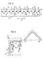
- a roller conveyor 10 for supporting T, U, I, L, or bead profiles is shown schematically.
- the roller conveyor 10 is part of a profile cutting system, as described in DE 35 10 381 C2. It consists of two roller strips 11, 12 running almost parallel to one another, which are automatically adjustable perpendicularly (arrow direction 9) to the longitudinal conveying direction 16 via a drive system 14, 15 connected to the controller 13 of the profile cutting system.
- the distance a (FIG. 3) between the disc-shaped support rollers 17, 18 arranged on the roller strips 11, 12 is increased or decreased.
- Each drive system 14, 16 is controlled transversely to the longitudinal conveying direction 16 independently of the other.
- a large number of disk-shaped support rollers 17, 18 are rotatably mounted in alignment in a row on the adjacent roller strips 11, 12 in the longitudinal conveying direction 16 of the profiles 19 (FIG. 3).
- the disc-shaped support rollers 17, 18 have their outer surfaces 21, 22 facing away from the bearing point and form a lateral closure. No components, such as axles, project from these outer surfaces 21, 22 of the support rollers 17, 18 beyond the dimension s + r (FIG. 3) to be explained in more detail below.
- the support rollers 17, 18 of the roller strips 11, 12 are offset in the longitudinal conveying direction 16 (FIG. 2) from one another on a base frame 20. With this arrangement, the support rollers 17, 18 can advantageously be arranged at any small distance from one another, so that the smallest profile heights h can be positioned.
- contact elements 24, in particular contact rollers are fixedly arranged.
- the arrangement of the contact elements 24 is carried out in such a way that the disc-shaped support rollers 17 can be brought into contact with the contact elements 24 with their outer surface 22 at a maximum distance a from the support rollers 18 fastened to the opposite roller strip 12.
- a U, I, T, L, or bead profile is placed on the support surface of the disk-shaped support rollers 17, 18 via a cross conveyor, not shown.
- the L-profile 19 shown in FIG. 3 (Angle profile), is conveyed horizontally to the disc-shaped support rollers 17, 18 with an arrangement lying on both end faces 26, 27.
- the cross-conveying of the L-profile 19 has ended at the moment when the flange 28 of the profile 19 associated with the end face 27 abuts the contact elements 24. Then the cross conveyor is lowered and the L-profile 19 is lowered with its flange 28 into the space 29 formed between the contact elements 24 and the disk-shaped support roller 17.
- the lateral dimension of the intermediate space 29 is automatically predetermined by the controller 13, starting from the contact surface 30 (FIG. 2) of the contact elements 24; it is determined from the addition of the flange width s or, for a bead profile, the bead width and the radius r.
- This lateral minimum dimension of the intermediate space 29 can be set before or after the profiles 19 are put down by driving the roller bar 11 with the support rollers 17.
- the distance a between the outer surfaces 21, 22 of the support rollers 17, 18 from the controller 13 is reduced by a reduction in the profile height h by the respective flange s or the bead width and the radii r.
- the distance a between the outer surfaces 21, 22 of the disk-shaped support rollers 17, 18 is additionally reduced by the controller 13 by an amount k which is dependent on the respective profile height h.
- This measure advantageously compensates for manufacturing tolerances and bending of the profiles 19, so that they always have flanges 28 directed downward toward the support rollers 17, 18 in the Intermediate space 29 is lowered and placed with its web surface 31 on the support rollers 17, 18.
- the method according to the invention was described using an L-profile 19.
- this method can also be used for U, I, T, or bead profiles, so that advantageously all profiles required in the profile processing industry can be supported on a single longitudinal conveyor in accordance with these methods.
- the above-mentioned profiles are shown schematically in FIGS. 4a, b, c, d, FIG. 4a a U-profile, FIG. 4b an I-profile, FIG. 4c a T-profile and FIG. 4d a bead profile shows.
Claims (6)
- Procédé pour soutenir des pièces d'oeuvre en forme de barreaux, qui sont disposées sur des galets d'appui en forme de rondelles, d'un transporteur longitudinal, procédé caractérisé en ce que les pièces d'oeuvre réalisées sous la forme de profilés en U, en I, en L, en T ou bien les profilés à boudins (19) sont déposées par leurs surfaces d'âme (31) sur au moins deux galets de soutien en forme de disques (17, 18) placés l'un à côté de l'autre, et sont appliquées par leurs semelles (28) contre des éléments d'appui (24) disposés à poste fixe le long de la direction de transport longitudinal (16) perpendiculairement à la surface d'appui (23) des galets de soutien en forme de disques (17, 18).
- Procédé selon la revendication 1, caractérisé en ce que les galets de soutien en forme de disques (17, 18) sont disposés dans la direction de transport longitudinal (16) des profilés (19) les uns derrière les autres sur respectivement une des deux lignes de galets (11, 12) placées l'une à côté de l'autre et susceptibles d'être déplacées perpendiculairement à la direction de transport longitudinal (16).
- Procédé selon une des revendications 1 ou 2, caractérisé en ce que les galets d'appui (17, 18) des lignes de galets (11, 12) sont décalés les uns par rapport aux autres dans la direction de transport longitudinal (16).
- Procédé selon une des revendications 1 à 3, caractérisé en ce que les profilés (19) sont déposés sur les galets de soutien en forme de disques (17, 18) avec une grande largeur d'appui (23), et que la distance (a) entre les surfaces externes (21, 22) des galets de soutien en forme de disques (17, 18) qui détermine cette largeur d'appui (23), est réglée par une commande (13) en réduisant la valeur mémorisée de la hauteur (h) du profilé (19) de l'épaisseur respective de la semelle ou du boudin (s) et du rayon (r).
- Procédé selon la revendication 4, caractérisé en ce que la distance (a) entre les surfaces externes (21, 22) des galets de soutien en forme de disques (17, 18) est diminuée par la commande (13) d'une valeur (k) dépendant de la hauteur (h) du profilé.
- Dispositif pour la mise en oeuvre du procédé selon une des revendications 1 à 5, caractérisé en ce qu'il comporte deux lignes de galets (11, 12) avec des galets de soutien en forme de disques (17, 18) montés de façon à pouvoir tourner et deux entraînements pour déplacer les lignes de galets (11, 12) perpendiculairement à la direction de transport longitudinal (16).
Priority Applications (1)
| Application Number | Priority Date | Filing Date | Title |
|---|---|---|---|
| AT88118383T ATE69986T1 (de) | 1987-12-12 | 1988-11-04 | Verfahren zum unterstuetzen von stabfoermigen werkstuecken. |
Applications Claiming Priority (2)
| Application Number | Priority Date | Filing Date | Title |
|---|---|---|---|
| DE3742174 | 1987-12-12 | ||
| DE3742174A DE3742174C1 (de) | 1987-12-12 | 1987-12-12 | Verfahren zum Unterstuetzen von stabfoermigen Werkstuecken |
Publications (3)
| Publication Number | Publication Date |
|---|---|
| EP0321685A2 EP0321685A2 (fr) | 1989-06-28 |
| EP0321685A3 EP0321685A3 (en) | 1989-07-26 |
| EP0321685B1 true EP0321685B1 (fr) | 1991-12-04 |
Family
ID=6342459
Family Applications (1)
| Application Number | Title | Priority Date | Filing Date |
|---|---|---|---|
| EP88118383A Expired - Lifetime EP0321685B1 (fr) | 1987-12-12 | 1988-11-04 | Procédé pour soutenir des poutrelles |
Country Status (7)
| Country | Link |
|---|---|
| US (1) | US5033610A (fr) |
| EP (1) | EP0321685B1 (fr) |
| JP (1) | JP2736084B2 (fr) |
| AT (1) | ATE69986T1 (fr) |
| DE (1) | DE3742174C1 (fr) |
| FI (1) | FI90837C (fr) |
| NO (1) | NO171711C (fr) |
Families Citing this family (9)
| Publication number | Priority date | Publication date | Assignee | Title |
|---|---|---|---|---|
| EP0423389B1 (fr) * | 1989-10-19 | 1996-09-11 | Fa. Horst K. Lotz | Machine de découpage au chalumeau avec moignons cyclindriques de support, dans le cadre de la coulée continue |
| US5128512A (en) * | 1990-07-26 | 1992-07-07 | Masahiro Seki | Laser beam machining device |
| DE19626887A1 (de) * | 1996-07-04 | 1998-01-15 | Schloemann Siemag Ag | Auflauf- und Abbremsvorrichtung, insbesondere für Mittelstahl-Walzprofile |
| GB2322826B (en) * | 1997-03-04 | 2001-09-26 | Edwin James Dumorris Eddy | Longitudinal cold separation unit - L. C. S. Unit |
| DE19732795C1 (de) * | 1997-07-30 | 1998-09-17 | Oxytechnik Ges Systemtech | Einrichtung zum Fördern von Profilen |
| JP4396443B2 (ja) | 2004-08-18 | 2010-01-13 | コニカミノルタエムジー株式会社 | 感光性平版印刷版の製造方法及び使用方法 |
| ITMI20071768A1 (it) * | 2007-09-14 | 2009-03-15 | Ficep Spa | Macchina utensile per il taglio o la foratura di profilati |
| CN105521992B (zh) * | 2015-12-09 | 2017-11-03 | 日照钢铁控股集团有限公司 | 一种高强度船用型钢制备工艺 |
| JP6567096B2 (ja) * | 2016-02-08 | 2019-08-28 | 三菱電機株式会社 | フィンスタック装置 |
Family Cites Families (23)
| Publication number | Priority date | Publication date | Assignee | Title |
|---|---|---|---|---|
| US571828A (en) * | 1896-11-24 | Bag gage-loader | ||
| DE367985C (de) * | 1921-08-14 | 1923-01-29 | Josef Gerster | Werkstuecktisch mit federnd gelagerten verstellbaren Rollen fuer Bohrmaschinen, Stanzen u. dgl. zum Bohren von Profileisen mit gleichem Streichmass |
| NL291459A (fr) * | 1962-04-16 | |||
| DE1752747A1 (de) * | 1968-07-10 | 1971-03-11 | Zeiss Carl Fa | Vorrichtung zum Schweissen duennwandiger,in einer Richtung stark ausgedehnter Profile |
| DE2219797A1 (de) * | 1971-08-05 | 1973-02-22 | Boldrini Spa | Zusatzgeraet fuer blechverformungspressen |
| SU553168A1 (ru) * | 1973-10-27 | 1977-04-05 | Рольганг дл транспортировки грузов различной ширины | |
| CA998631A (en) * | 1974-12-30 | 1976-10-19 | Interlake | Structure leveling assembly |
| JPS515906U (fr) * | 1975-06-20 | 1976-01-16 | ||
| US4023672A (en) * | 1975-10-03 | 1977-05-17 | Haley Ernest K | Transfer table |
| JPS5237982U (fr) * | 1976-08-18 | 1977-03-17 | ||
| SU608715A1 (ru) * | 1976-09-21 | 1978-05-30 | Предприятие П/Я Р-6476 | Устройство дл транспортировани длинномерных изделий |
| JPS5427751U (fr) * | 1977-07-26 | 1979-02-23 | ||
| DE2742072B2 (de) * | 1977-09-19 | 1979-10-04 | Peddinghaus, Rolf, 5828 Ennepetal | Vorschubeinrichtung für das Bearbeiten von sich längs erstreckenden Werkstücken mit Hilfe einer Meßvorrichtung |
| US4255993A (en) * | 1977-10-27 | 1981-03-17 | Potomac Applied Mechanics, Inc. | Angle iron cutting |
| DE2813461A1 (de) * | 1978-03-29 | 1979-10-11 | Ipu Ltd | Verfahren zum brennschneiden von stahlbrammen an stranggiessanlagen und anlage zur durchfuehrung des verfahrens |
| US4422543A (en) * | 1979-01-03 | 1983-12-27 | Potomac Applied Mechanics, Inc. | Universal conveyor |
| JPS5785627A (en) * | 1980-11-14 | 1982-05-28 | Sumitomo Metal Ind Ltd | Controlling method for expanding of large diameter tube |
| DE3136394A1 (de) * | 1981-09-14 | 1983-03-24 | Peddinghaus, Rolf, 5828 Ennepetal | Bohranlage fuer werkstuecke endlicher laenge |
| DE3428139A1 (de) * | 1984-07-31 | 1986-02-13 | Oxytechnik Gesellschaft für Systemtechnik mbH, 6236 Eschborn | Einrichtung zum transportieren von profilen |
| JPS6182737U (fr) * | 1984-10-30 | 1986-05-31 | ||
| DE3510381A1 (de) * | 1985-03-22 | 1986-09-25 | Oxytechnik Gesellschaft für Systemtechnik mbH, 6236 Eschborn | Verfahren zum bearbeiten von werkstuecken, insbesondere zum thermischen trennen von profilen mit einem schneidbrenner |
| JPH0615365B2 (ja) * | 1986-03-28 | 1994-03-02 | 日電アネルバ株式会社 | 移送装置 |
| DE3710916A1 (de) * | 1987-04-01 | 1988-10-20 | Schulze Berge Otto | Vorrichtung zur fuehrung von paletten auf einer rollenbahn |
-
1987
- 1987-12-12 DE DE3742174A patent/DE3742174C1/de not_active Expired
-
1988
- 1988-11-04 EP EP88118383A patent/EP0321685B1/fr not_active Expired - Lifetime
- 1988-11-04 AT AT88118383T patent/ATE69986T1/de not_active IP Right Cessation
- 1988-12-05 NO NO885398A patent/NO171711C/no unknown
- 1988-12-09 US US07/282,199 patent/US5033610A/en not_active Expired - Lifetime
- 1988-12-12 JP JP63312147A patent/JP2736084B2/ja not_active Expired - Lifetime
- 1988-12-12 FI FI885746A patent/FI90837C/fi not_active IP Right Cessation
Also Published As
| Publication number | Publication date |
|---|---|
| NO171711B (no) | 1993-01-18 |
| FI885746A (fi) | 1989-06-13 |
| ATE69986T1 (de) | 1991-12-15 |
| EP0321685A3 (en) | 1989-07-26 |
| FI90837B (fi) | 1993-12-31 |
| US5033610A (en) | 1991-07-23 |
| NO885398L (no) | 1989-06-13 |
| FI90837C (fi) | 1994-04-11 |
| FI885746A0 (fi) | 1988-12-12 |
| NO171711C (no) | 1993-04-28 |
| NO885398D0 (no) | 1988-12-05 |
| DE3742174C1 (de) | 1989-04-20 |
| JP2736084B2 (ja) | 1998-04-02 |
| EP0321685A2 (fr) | 1989-06-28 |
| JPH01197213A (ja) | 1989-08-08 |
Similar Documents
| Publication | Publication Date | Title |
|---|---|---|
| DE2149191C2 (de) | Vorrichtung zum Abschmelzen der Absprengkappen bei der Herstellung von Hohlgläsern | |
| DE2760217C2 (fr) | ||
| AT390432B (de) | Verfahren zur herstellung eines abstandhalterrahmens und vorrichtung sowie anlage zur durchfuehrung des verfahrens | |
| DE2461495A1 (de) | Einrichtung zum zurichten von streifen unterschiedlicher breite | |
| EP0192613B1 (fr) | Dispositif pour tenir et transporter des pièces moulées, notamment des tôles de carrosserie dans l'industrie automobile | |
| EP0321685B1 (fr) | Procédé pour soutenir des poutrelles | |
| EP0324333B1 (fr) | Dispositif pour remplir du verre isolant avec un gaz spécial | |
| DE3230455A1 (de) | Vorrichtung zum schweissen von karosserien fuer kraftfahrzeuge | |
| DE2906692C2 (de) | Verfahren zur Herstellung von Schlitzrohren für eine Rohrschweißmaschine und Vorrichtung zur Durchführung des Verfahrens | |
| DE1778337B1 (de) | Endloser foerderer zur verwendung bei einer automatischen lackieranlage fuer plattenfoermige werkstuecke | |
| EP0320611A2 (fr) | Dispositif pour couper des profilés en U, T, L, I, plat ou à bourrelet | |
| DE2519278A1 (de) | Verfahren zum formen von glasplatten mittels walzen | |
| DE3218253C2 (fr) | ||
| DE2106091C3 (de) | Vorrichtung zum verschachtelten, lageweisen Stapeln von profiliertem Walzgut | |
| EP0489681B1 (fr) | Procédé et dispositif pour déplacer des pièces en forme de bandes ou de panneaux, empilés et juxtaposés sur une surface de support à faible coefficient de frottement | |
| DE3737228A1 (de) | Einrichtung zum buntaufteilen von plattenfoermigen werkstuecken | |
| EP0550000A1 (fr) | Dispositif de peinture par électrophorèse | |
| DE19934361A1 (de) | Werkstück-Transfersystem | |
| DE2460386B2 (de) | Bandbund-Transportvorrichtung | |
| DE2314715C3 (de) | Vorrichtung zur Herstellung von Ganzglasdoppelscheiben wechselnder Höhe durch Verschweißender Kanten innerhalb eines Tunnelofens | |
| DE19619231B4 (de) | Einrichtung zum Transportieren, Spannen und Laserstrahlschweißen von mindestens zwei Blechplatinen | |
| EP0123120B1 (fr) | Plaque pour une tête de buse d'un système de boîte à buses pour le soufflage de surfaces de forme bombée | |
| DE2364391C3 (de) | Speicher | |
| EP0615405B1 (fr) | Système d'usinage et d'assemblage pour pièces de petites dimensions | |
| DE19620493A1 (de) | Hubvorrichtung für Rollenschienen von Rollentischen |
Legal Events
| Date | Code | Title | Description |
|---|---|---|---|
| PUAI | Public reference made under article 153(3) epc to a published international application that has entered the european phase |
Free format text: ORIGINAL CODE: 0009012 |
|
| PUAL | Search report despatched |
Free format text: ORIGINAL CODE: 0009013 |
|
| AK | Designated contracting states |
Kind code of ref document: A2 Designated state(s): AT BE CH ES FR GB IT LI NL SE |
|
| AK | Designated contracting states |
Kind code of ref document: A3 Designated state(s): AT BE CH ES FR GB IT LI NL SE |
|
| 17P | Request for examination filed |
Effective date: 19900112 |
|
| 17Q | First examination report despatched |
Effective date: 19900927 |
|
| GRAA | (expected) grant |
Free format text: ORIGINAL CODE: 0009210 |
|
| AK | Designated contracting states |
Kind code of ref document: B1 Designated state(s): AT BE CH ES FR GB IT LI NL SE |
|
| PG25 | Lapsed in a contracting state [announced via postgrant information from national office to epo] |
Ref country code: SE Effective date: 19911204 Ref country code: NL Effective date: 19911204 Ref country code: FR Effective date: 19911204 Ref country code: ES Free format text: THE PATENT HAS BEEN ANNULLED BY A DECISION OF A NATIONAL AUTHORITY Effective date: 19911204 Ref country code: BE Effective date: 19911204 |
|
| REF | Corresponds to: |
Ref document number: 69986 Country of ref document: AT Date of ref document: 19911215 Kind code of ref document: T |
|
| ITF | It: translation for a ep patent filed |
Owner name: DE DOMINICIS & MAYER S.R.L. |
|
| GBT | Gb: translation of ep patent filed (gb section 77(6)(a)/1977) | ||
| EN | Fr: translation not filed | ||
| NLV1 | Nl: lapsed or annulled due to failure to fulfill the requirements of art. 29p and 29m of the patents act | ||
| PLBE | No opposition filed within time limit |
Free format text: ORIGINAL CODE: 0009261 |
|
| STAA | Information on the status of an ep patent application or granted ep patent |
Free format text: STATUS: NO OPPOSITION FILED WITHIN TIME LIMIT |
|
| 26N | No opposition filed | ||
| PG25 | Lapsed in a contracting state [announced via postgrant information from national office to epo] |
Ref country code: LI Effective date: 19921130 Ref country code: CH Effective date: 19921130 |
|
| REG | Reference to a national code |
Ref country code: CH Ref legal event code: PL |
|
| PGFP | Annual fee paid to national office [announced via postgrant information from national office to epo] |
Ref country code: AT Payment date: 19951129 Year of fee payment: 8 |
|
| PG25 | Lapsed in a contracting state [announced via postgrant information from national office to epo] |
Ref country code: AT Effective date: 19961104 |
|
| PGFP | Annual fee paid to national office [announced via postgrant information from national office to epo] |
Ref country code: GB Payment date: 19971023 Year of fee payment: 10 |
|
| PG25 | Lapsed in a contracting state [announced via postgrant information from national office to epo] |
Ref country code: GB Free format text: LAPSE BECAUSE OF NON-PAYMENT OF DUE FEES Effective date: 19981104 |
|
| GBPC | Gb: european patent ceased through non-payment of renewal fee |
Effective date: 19981104 |
|
| PG25 | Lapsed in a contracting state [announced via postgrant information from national office to epo] |
Ref country code: IT Free format text: LAPSE BECAUSE OF NON-PAYMENT OF DUE FEES;WARNING: LAPSES OF ITALIAN PATENTS WITH EFFECTIVE DATE BEFORE 2007 MAY HAVE OCCURRED AT ANY TIME BEFORE 2007. THE CORRECT EFFECTIVE DATE MAY BE DIFFERENT FROM THE ONE RECORDED. Effective date: 20051104 |