EP0321685B1 - Method for supporting beams - Google Patents
Method for supporting beams Download PDFInfo
- Publication number
- EP0321685B1 EP0321685B1 EP88118383A EP88118383A EP0321685B1 EP 0321685 B1 EP0321685 B1 EP 0321685B1 EP 88118383 A EP88118383 A EP 88118383A EP 88118383 A EP88118383 A EP 88118383A EP 0321685 B1 EP0321685 B1 EP 0321685B1
- Authority
- EP
- European Patent Office
- Prior art keywords
- disc
- support rollers
- shaped
- shaped support
- profiles
- Prior art date
- Legal status (The legal status is an assumption and is not a legal conclusion. Google has not performed a legal analysis and makes no representation as to the accuracy of the status listed.)
- Expired - Lifetime
Links
- 238000000034 method Methods 0.000 title claims abstract description 14
- 239000011324 bead Substances 0.000 claims description 13
- 230000000284 resting effect Effects 0.000 claims 1
- 238000005520 cutting process Methods 0.000 description 13
- 238000011161 development Methods 0.000 description 2
- 230000018109 developmental process Effects 0.000 description 2
- 239000002184 metal Substances 0.000 description 2
- 229910052751 metal Inorganic materials 0.000 description 2
- 238000005452 bending Methods 0.000 description 1
- 238000005266 casting Methods 0.000 description 1
- 230000003247 decreasing effect Effects 0.000 description 1
- 230000001419 dependent effect Effects 0.000 description 1
- 238000005553 drilling Methods 0.000 description 1
- 238000004519 manufacturing process Methods 0.000 description 1
- 238000003860 storage Methods 0.000 description 1
Images


Classifications
-
- B—PERFORMING OPERATIONS; TRANSPORTING
- B21—MECHANICAL METAL-WORKING WITHOUT ESSENTIALLY REMOVING MATERIAL; PUNCHING METAL
- B21D—WORKING OR PROCESSING OF SHEET METAL OR METAL TUBES, RODS OR PROFILES WITHOUT ESSENTIALLY REMOVING MATERIAL; PUNCHING METAL
- B21D43/00—Feeding, positioning or storing devices combined with, or arranged in, or specially adapted for use in connection with, apparatus for working or processing sheet metal, metal tubes or metal profiles; Associations therewith of cutting devices
- B21D43/02—Advancing work in relation to the stroke of the die or tool
- B21D43/021—Control or correction devices in association with moving strips
- B21D43/023—Centering devices, e.g. edge guiding
-
- B—PERFORMING OPERATIONS; TRANSPORTING
- B22—CASTING; POWDER METALLURGY
- B22D—CASTING OF METALS; CASTING OF OTHER SUBSTANCES BY THE SAME PROCESSES OR DEVICES
- B22D11/00—Continuous casting of metals, i.e. casting in indefinite lengths
- B22D11/12—Accessories for subsequent treating or working cast stock in situ
- B22D11/126—Accessories for subsequent treating or working cast stock in situ for cutting
-
- B—PERFORMING OPERATIONS; TRANSPORTING
- B23—MACHINE TOOLS; METAL-WORKING NOT OTHERWISE PROVIDED FOR
- B23K—SOLDERING OR UNSOLDERING; WELDING; CLADDING OR PLATING BY SOLDERING OR WELDING; CUTTING BY APPLYING HEAT LOCALLY, e.g. FLAME CUTTING; WORKING BY LASER BEAM
- B23K37/00—Auxiliary devices or processes, not specially adapted to a procedure covered by only one of the preceding main groups
- B23K37/04—Auxiliary devices or processes, not specially adapted to a procedure covered by only one of the preceding main groups for holding or positioning work
-
- B—PERFORMING OPERATIONS; TRANSPORTING
- B23—MACHINE TOOLS; METAL-WORKING NOT OTHERWISE PROVIDED FOR
- B23Q—DETAILS, COMPONENTS, OR ACCESSORIES FOR MACHINE TOOLS, e.g. ARRANGEMENTS FOR COPYING OR CONTROLLING; MACHINE TOOLS IN GENERAL CHARACTERISED BY THE CONSTRUCTION OF PARTICULAR DETAILS OR COMPONENTS; COMBINATIONS OR ASSOCIATIONS OF METAL-WORKING MACHINES, NOT DIRECTED TO A PARTICULAR RESULT
- B23Q7/00—Arrangements for handling work specially combined with or arranged in, or specially adapted for use in connection with, machine tools, e.g. for conveying, loading, positioning, discharging, sorting
- B23Q7/05—Arrangements for handling work specially combined with or arranged in, or specially adapted for use in connection with, machine tools, e.g. for conveying, loading, positioning, discharging, sorting by means of roller-ways
-
- B—PERFORMING OPERATIONS; TRANSPORTING
- B65—CONVEYING; PACKING; STORING; HANDLING THIN OR FILAMENTARY MATERIAL
- B65G—TRANSPORT OR STORAGE DEVICES, e.g. CONVEYORS FOR LOADING OR TIPPING, SHOP CONVEYOR SYSTEMS OR PNEUMATIC TUBE CONVEYORS
- B65G13/00—Roller-ways
- B65G13/11—Roller frames
- B65G13/12—Roller frames adjustable
Definitions
- the invention relates to a method for supporting rod-shaped workpieces, which are placed on disc-shaped support rollers of a longitudinal conveyor.
- the workpieces are conveyed into the cutting area of a cutting station and positioned in the cutting area relative to the cutting torch.
- the workpieces are designed as T, U, I, L, flat or bead profiles.
- these profiles with the different cross-sectional shapes are placed in a carriage on profile receiving plates and the carriage is moved along a track in the cutting area.
- these profiles are placed on a roller conveyor with cylindrical rollers, which extend over the entire profile contact surface.
- fixed contact rollers are provided perpendicular to the support surface within the support surface between the cylindrical rollers of the roller conveyor.
- the profiles are positioned in a positioning device arranged at the end of the roller conveyor between adjustable support rollers.
- Such long T, U, I, L, flat or bead profiles have lateral deviations due to curvatures or bends over their longitudinal extent, which make conveying into the opening of the positioning device more difficult.
- the profiles must be held in position at their free end during positioning in the positioning device.
- drilling stations for profiles are known, in which the profiles are also arranged on roller conveyors with cylindrical rollers.
- sheet metal strips are conveyed to the forming press intermittently by means of two driven support and guide rollers.
- the metal strips lie on the support rollers.
- One support and one guide roller is attached to a common support. With such a conveyor device, no U, I, L, T or bead profiles can be placed with their webs on the support rollers.
- the invention has for its object to provide a positionally stable support in conveying the different profile cross sections and dimensions on a single longitudinal conveyor.
- the workpieces designed as U, I, L, T or bead profiles are placed with their web surfaces on at least two adjacent disc-shaped support rollers and fixedly arranged perpendicular to the contact surface of the disc-shaped support rollers along the longitudinal conveying direction with the flanges.
- the advantages achieved with the invention consist in particular in a positionally stable conveying of the profiles.
- a "threading" into the opening of the positioning device takes place without any problems, since only a predetermined lateral deviation is permitted by the contact elements arranged outside the bearing surface of the disc rollers in connection with the adjustable roller strip assigned to them.
- the support rollers of the positioning device can advantageously be omitted.
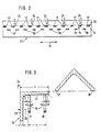
- a roller conveyor 10 for supporting T, U, I, L, or bead profiles is shown schematically.
- the roller conveyor 10 is part of a profile cutting system, as described in DE 35 10 381 C2. It consists of two roller strips 11, 12 running almost parallel to one another, which are automatically adjustable perpendicularly (arrow direction 9) to the longitudinal conveying direction 16 via a drive system 14, 15 connected to the controller 13 of the profile cutting system.
- the distance a (FIG. 3) between the disc-shaped support rollers 17, 18 arranged on the roller strips 11, 12 is increased or decreased.
- Each drive system 14, 16 is controlled transversely to the longitudinal conveying direction 16 independently of the other.
- a large number of disk-shaped support rollers 17, 18 are rotatably mounted in alignment in a row on the adjacent roller strips 11, 12 in the longitudinal conveying direction 16 of the profiles 19 (FIG. 3).
- the disc-shaped support rollers 17, 18 have their outer surfaces 21, 22 facing away from the bearing point and form a lateral closure. No components, such as axles, project from these outer surfaces 21, 22 of the support rollers 17, 18 beyond the dimension s + r (FIG. 3) to be explained in more detail below.
- the support rollers 17, 18 of the roller strips 11, 12 are offset in the longitudinal conveying direction 16 (FIG. 2) from one another on a base frame 20. With this arrangement, the support rollers 17, 18 can advantageously be arranged at any small distance from one another, so that the smallest profile heights h can be positioned.
- contact elements 24, in particular contact rollers are fixedly arranged.
- the arrangement of the contact elements 24 is carried out in such a way that the disc-shaped support rollers 17 can be brought into contact with the contact elements 24 with their outer surface 22 at a maximum distance a from the support rollers 18 fastened to the opposite roller strip 12.
- a U, I, T, L, or bead profile is placed on the support surface of the disk-shaped support rollers 17, 18 via a cross conveyor, not shown.
- the L-profile 19 shown in FIG. 3 (Angle profile), is conveyed horizontally to the disc-shaped support rollers 17, 18 with an arrangement lying on both end faces 26, 27.
- the cross-conveying of the L-profile 19 has ended at the moment when the flange 28 of the profile 19 associated with the end face 27 abuts the contact elements 24. Then the cross conveyor is lowered and the L-profile 19 is lowered with its flange 28 into the space 29 formed between the contact elements 24 and the disk-shaped support roller 17.
- the lateral dimension of the intermediate space 29 is automatically predetermined by the controller 13, starting from the contact surface 30 (FIG. 2) of the contact elements 24; it is determined from the addition of the flange width s or, for a bead profile, the bead width and the radius r.
- This lateral minimum dimension of the intermediate space 29 can be set before or after the profiles 19 are put down by driving the roller bar 11 with the support rollers 17.
- the distance a between the outer surfaces 21, 22 of the support rollers 17, 18 from the controller 13 is reduced by a reduction in the profile height h by the respective flange s or the bead width and the radii r.
- the distance a between the outer surfaces 21, 22 of the disk-shaped support rollers 17, 18 is additionally reduced by the controller 13 by an amount k which is dependent on the respective profile height h.
- This measure advantageously compensates for manufacturing tolerances and bending of the profiles 19, so that they always have flanges 28 directed downward toward the support rollers 17, 18 in the Intermediate space 29 is lowered and placed with its web surface 31 on the support rollers 17, 18.
- the method according to the invention was described using an L-profile 19.
- this method can also be used for U, I, T, or bead profiles, so that advantageously all profiles required in the profile processing industry can be supported on a single longitudinal conveyor in accordance with these methods.
- the above-mentioned profiles are shown schematically in FIGS. 4a, b, c, d, FIG. 4a a U-profile, FIG. 4b an I-profile, FIG. 4c a T-profile and FIG. 4d a bead profile shows.
Abstract
Description
Die Erfindung betrifft ein Verfahren zum Unterstützen von stabförmigen Werkstücken, die auf scheibenförmigen Stützrollen eines Längsförderers abgelegt werden.The invention relates to a method for supporting rod-shaped workpieces, which are placed on disc-shaped support rollers of a longitudinal conveyor.
Beim thermischen Bearbeiten mit einem Schneidbrenner werden die Werkstücke in den Schneidbereich einer Schneidstation gefördert und im Schneidbereich relativ zum Schneidbrenner positioniert.During thermal processing with a cutting torch, the workpieces are conveyed into the cutting area of a cutting station and positioned in the cutting area relative to the cutting torch.
Aus dem gattungsbildenden Stand der Technik nach der DE 2813461 A1 ist es bekannt, Brammen mit rechteckförmigem Querschnitt auf scheibenförmigen Stützrollen abzulegen. Zum Brennschneiden der Brammen läuft eine Schneidstation in der Gießgeschwindigkeit des Stranges mit. Um dabei eine Gefährdung der Stützrollen durch die aus dem Schneidbrenner austretende Schneidflamme zu vermeiden, sollen die Stützrollen bei größeren Abweichungen von einer vorgegebenen Brennschneidbahn mittels einer geeigneten Einrichtung auf ihrer Achse verschiebbar sein.From the generic state of the art according to DE 2813461 A1 it is known to use slabs with a rectangular shape Place cross-section on disc-shaped support rollers. To flame cut the slabs, a cutting station runs at the casting speed of the strand. In order to avoid endangering the support rollers from the cutting flame emerging from the cutting torch, the support rollers should be displaceable on their axis in the event of major deviations from a predetermined flame cutting path by means of a suitable device.
Gemäß der DE 3428139 C2 sind die Werkstücke als T-, U-, I-, L-, Flach- oder Wulstprofile ausgebildet. Zum Transport werden diese Profile mit den unterschiedlichen Querschnittsformen in einem Wagen auf Profilaufnehmerplatten abgelegt und der Wagen entlang einer Laufbahn in den Schneidbereich bewegt.According to DE 3428139 C2, the workpieces are designed as T, U, I, L, flat or bead profiles. For transport, these profiles with the different cross-sectional shapes are placed in a carriage on profile receiving plates and the carriage is moved along a track in the cutting area.
Bei einer Profilschneidanlage nach der DE 3510381 C2 werden diese Profile auf einem Rollengang mit Zylinderrollen abgelegt, die sich über die gesamte Profilauflagefläche erstrecken. Als Führung der Profile sind senkrecht zu der Auflagefläche fest angeordnete Anlagerollen innerhalb der Auflagefläche zwischen den Zylinderrollen des Rollengang vorgesehen. Das Positionieren der Profile erfolgt in einer am Ende des Rollenganges angeordneten Positioniervorrichtung zwischen verstellbaren Stützrollen.In a profile cutting system according to DE 3510381 C2, these profiles are placed on a roller conveyor with cylindrical rollers, which extend over the entire profile contact surface. In order to guide the profiles, fixed contact rollers are provided perpendicular to the support surface within the support surface between the cylindrical rollers of the roller conveyor. The profiles are positioned in a positioning device arranged at the end of the roller conveyor between adjustable support rollers.
Derartige lange T-, U-, I-, L-, Flach- oder Wulstprofile weisen aufgrund von Krümmungen bzw. Biegungen über ihre Längserstreckung seitliche Abweichungen auf, die eine Förderung in die Öffnung der Positioniervorrichtung erschweren. Hinzu kommt, daß während der Positionierung in der Positioniervorrichtung die Profile an ihrem freien Ende in ihrer Lage gehalten werden müssen.Such long T, U, I, L, flat or bead profiles have lateral deviations due to curvatures or bends over their longitudinal extent, which make conveying into the opening of the positioning device more difficult. In addition, the profiles must be held in position at their free end during positioning in the positioning device.
Aus der DE 27 42 072 A2, der DE 33 31 844 C1 und der DE 31 36 394 A1 sind Bohrstationen für Profile bekannt, in denen die Profile ebenfalls auf Rollengängen mit Zylinderrollen angeordnet werden.From DE 27 42 072 A2, DE 33 31 844 C1 and DE 31 36 394 A1, drilling stations for profiles are known, in which the profiles are also arranged on roller conveyors with cylindrical rollers.
Bei einem Zusatzgerät für eine Verformungspresse werden Blechbänder mittels zwei angetriebenen Stütz- und Führungsrollen taktweise zu der Verformungspresse gefördert. Dabei liegen die Blechbänder auf den Stützrollen auf. Jeweils eine Stütz- und Führungsrolle ist auf einem gemeinsamen Träger befestigt. Bei einer derartigen Fördervorrichtung können keine U-, I-, L-, T- oder Wulstprofile mit ihren Stegen auf den Stützrollen abgelegt werden.In an additional device for a forming press, sheet metal strips are conveyed to the forming press intermittently by means of two driven support and guide rollers. The metal strips lie on the support rollers. One support and one guide roller is attached to a common support. With such a conveyor device, no U, I, L, T or bead profiles can be placed with their webs on the support rollers.
Eine Vorrichtung zum Fördern von Winkelprofilen, in der die Profile an jeder Seite zwischen zwei sich gegenüberliegenden, angetriebenen Rollen eingespannt ist, wird in der US-A-4,255,993 beschrieben. Nachteilig hierbei ist, daß die Profile mit ihrer Stirnseite in die Fördervorrichtung eingefädelt werden müssen, was die Längserstreckung der Anlage verdoppelt. Hinzu kommt, daß bei sich ändernden Abmessungen der Profile aufwendige Einstell- und Nachstellarbeiten vorgenommen werden müssen, um ein sicheres Greifen der Antriebsrollen zu gewährleisten. Bei sich ändernden Profilformen müssen jeweils andere Fördervorrichtungen eingesetzt werden.A device for conveying angular profiles, in which the profile is clamped on each side between two opposite, driven rollers, is described in US-A-4,255,993. The disadvantage here is that the end face of the profiles has to be threaded into the conveyor device, which doubles the length of the system. In addition, when the dimensions of the profiles change, complex adjustment and readjustment work has to be carried out to ensure that the drive rollers are gripped securely. In the case of changing profile shapes, different conveying devices must be used.
Der Erfindung liegt die Aufgabe zugrunde, eine lagestabile Unterstützung beim Fördern der unterschiedlichen Profilquerschnitte und -dimesionen auf einem einzigen Längsförderer zu ermöglichen.The invention has for its object to provide a positionally stable support in conveying the different profile cross sections and dimensions on a single longitudinal conveyor.
Diese Aufgabe wird erfindungsgemäß dadurch gelöst, daß die als U-, I-, L-, T- oder Wulstprofile ausgebildeten Werkstücke mit ihren Stegflächen auf mindestens zwei nebeneinanderliegenden scheibenförmigen Stützrollen abgelegt und an senkrecht zu der Auflagefläche der scheibenförmigen Stützrollen entlang der Längsförderrichtung fest angeordneten Anlageelementen mit den Flanschen angelegt werden.This object is achieved in that the workpieces designed as U, I, L, T or bead profiles are placed with their web surfaces on at least two adjacent disc-shaped support rollers and fixedly arranged perpendicular to the contact surface of the disc-shaped support rollers along the longitudinal conveying direction with the flanges.
Die mit der Erfindung erzielten Vorteile bestehen insbesondere in einer lagestabilen Förderung der Profile. Ein "Einfädeln" in die Öffnung der Positioniervorrichtung erfolgt ohne Probleme, da durch die außerhalb der Auflagefläche der Scheibenrollen angeordneten Anlageelemente in Verbindung mit der ihnen zugeordneten verstellbaren Rollenleiste nur eine vorbestimmte seitliche Abweichung zugelassen wird. Die Unterstützungsrollen der Positioniervorrichtung können vorteilhaft entfallen.The advantages achieved with the invention consist in particular in a positionally stable conveying of the profiles. A "threading" into the opening of the positioning device takes place without any problems, since only a predetermined lateral deviation is permitted by the contact elements arranged outside the bearing surface of the disc rollers in connection with the adjustable roller strip assigned to them. The support rollers of the positioning device can advantageously be omitted.
Weitere vorteilhafte Ausbildungen der Erfindung sind in den Unteransprüchen angegeben.Further advantageous developments of the invention are specified in the subclaims.
Ein Ausführungsbeispiel der Erfindung ist in der Zeichnung dargestellt und wird im folgenden näher beschrieben.An embodiment of the invention is shown in the drawing and will be described in more detail below.
Es zeigen:
- Fig. 1
- eine Vorderansicht des Rollenganges mit scheibenförmigen Stützrollen zur Durchführung des Verfahrens;
- Fig. 2
- ein Ausschnitt einer Draufsicht;
- Fig. 3
- ein auf den scheibenförmigen Stützrollen angeordnetes L-Profil (Winkel-Profil),
- Fig. 4
- eine schematische Darstellung eines U-, I-, T-bzw. Wulstprofiles.
- Fig. 1
- a front view of the roller conveyor with disc-shaped support rollers for performing the method;
- Fig. 2
- a section of a plan view;
- Fig. 3
- an L-profile (angle profile) arranged on the disc-shaped support rollers,
- Fig. 4
- is a schematic representation of a U, I, T or. Bead profile.
In Fig. 1 und Fig. 2 ist ein Rollengang 10 zum Unterstützen von T-, U-, I-, L-, oder Wulstprofilen schematisch dargestellt. Der Rollengang 10 ist Bestandteil eines Profilschneidsystems, wie es in der DE 35 10 381 C2 näher beschrieben ist. Er besteht aus zwei nahezu parallel zueinander verlaufenden Rollenleisten 11, 12, die über ein mit der Steuerung 13 des Profilschneidsystems in Verbindung stehendes Antriebssystem 14,15 senkrecht (Pfeilrichtung 9) zur Längsförderrichtung 16 automatisch verstellbar sind. Hierbei wird der Abstand a (Fig. 3) zwischen den an den Rollenleisten 11, 12 angeordneten scheibenförmigen Stützrollen 17, 18 vergrößert oder verkleinert. Die Ansteuerung jedes Antriebssystems 14, 16 quer zur Längsförderrichtung 16 erfolgt unabhängig vom jeweils anderen.In Fig. 1 and Fig. 2, a
An den nebeneinanderliegenden Rollenleisten 11,12 sind in Längsförderrichtung 16 der Profile 19 (Fig. 3) hintereinander eine Vielzahl von scheibenförmigen Stützrollen 17, 18 in einer Flucht drehbar gelagert. Bei dieser Lagerung weisen die scheibenförmigen Stützrollen 17,18 mit ihren Außenflächen 21, 22 zu einer von der Lagerstelle abgewandten Seite und bilden einen seitlichen Abschluß. Von diesen Außenflächen 21,22 der Stützrollen 17,18 stehen keine über das nachfolgend noch näher zu erläuternde Maß s + r (Fig. 3) angeordneten Bauteile, wie Achsen, ab. Die Stützrollen 17, 18 der Rollenleisten 11, 12 sind in Längsförderrichtung 16 versetzt (Fig. 2) zueinander auf einem Grundgestell 20 angeordnet. Durch diese Anordnung können vorteilhaft die Stützrollen 17,18 in beliebig geringem Abstand zueinander angeordnet werden, so daß kleinste Profilhöhen h positioniert werden können.A large number of disk-
Außerhalb des maximal einstellbaren Abstandes a sind senkrecht zu der Stützweite 23 der scheibenförmigen Stützrollen 17,18 neben der Rollenleiste 11 Anlageelemente 24, insbesondere Anlagerollen, fest angeordnet.Outside the maximum adjustable distance a perpendicular to the
Die Anordnung der Anlageelemente 24 ist hierbei so vorgenommen, daß die scheibenförmigen Stützrollen 17 bei maximalem Abstand a zu den an der gegenüberliegenden Rollenleiste 12 befestigten Stützrollen 18 mit ihrer Außenfläche 22 an den Anlageelementen 24 zur Anlage gebracht werden können.The arrangement of the
Im Betrieb wird ein U-, I-, T-, L-, oder Wulstprofil über einen nicht näher dargestellten Querförderer auf der Auflagefläche der scheibenförmigen Stützrollen 17, 18 abgelegt. Das in Fig. 3 dargestellte L-Profil 19 (Winkel-Profil), wird hierbei waagerecht mit auf beiden Stirnflächen 26,27 aufliegender Anordnung zu den scheibenförmigen Stützrollen 17, 18 gefördert. Wie aus der Fig. 3 ersichtlich, ist die Querförderung des L-Profiles 19 in dem Augenblick beendet, wenn der der Stirnfläche 27 zugehörige Flansch 28 des Profiles 19 an den Anlageelementen 24 anliegt. Anschließend wird der Querförderer abgesenkt und das L-Profil 19 wird mit seinem Flansch 28 in den zwischen den Anlageelementen 24 und der scheibenförmigen Stützrolle 17 gebildeten Zwischenraum 29 abgesenkt. Die seitliche Abmessung des Zwischenraumes 29 wird ausgehend von der Anlagefläche 30 (Fig. 2) der Anlageelemente 24 von der Steuerung 13 automatisch vorgegeben; sie bestimmt sich aus der Addition der Flanschbreite s bzw. bei einem Wulstprofil der Wulstbreite und des Radiuses r. Diese seitliche Mindestabmessung des Zwischenraumes 29 kann vor oder nach dem Ablegen der Profile 19 durch Ansteuern der Rollenleiste 11 mit den Stützrollen 17 eingestellt werden. Um eine möglichst große Stützweite 23 der Profile 19 auf den scheibenförmigen Stützrollen 17,18 zu erhalten, wird der Abstand a zwischen den Außenflächen 21, 22 der Stützrollen 17, 18 von der Steuerung 13 durch eine Verminderung der Profilhöhe h um die jeweilige Flansch- s bzw. Wulstbreite und der Radien r vorgegeben. Gemäß einer Weiterbildung des Verfahrens zur Unterstützung der Profile 19 wird der Abstand a zwischen den Außenflächen 21, 22 der scheibenförmigen Stützrollen 17, 18 von der Steuerung 13 zusätzlich um einen von der jeweiligen Profilhöhe h abhängigen Betrag k vermindert. Durch diese Maßnahme werden vorteilhaft Fertigungstoleranzen und Verbiegungen der Profile 19 ausgeglichen, so daß diese immer mit nach unten zu den Stützrollen 17, 18 gerichteten Flanschen 28 in den Zwischenraum 29 abgesenkt und mit ihrer Stegfläche 31 auf den Stützrollen 17, 18 abgelegt werden.In operation, a U, I, T, L, or bead profile is placed on the support surface of the disk-
Im vorliegenden Ausführungsbeispiel wurde das Verfahren nach der Erfindung anhand eines L-Profiles 19 beschrieben. Grundsätzlich ist dieses Verfahren auch bei U-, I-, T-, oder Wulstprofilen anwendbar, so daß vorteilhaft alle in der Profil verarbeitenden Industrie benötigten Profile entsprechend diesen Verfahren auf einem einzigen Längsförderer unterstützt werden können. Die vorstehend genannten Profile sind in den Figuren 4a, b, c, d schematisch dargestellt, wobei Fig. 4a ein U-Profil, Fig. 4b ein I-Profil, Fig. 4c ein T-Profil und Fig. 4d ein Wulst-Profil zeigt.In the present exemplary embodiment, the method according to the invention was described using an L-
Claims (6)
- Method for supporting bar-shaped workpieces which are placed on disc-shaped support rollers of a longitudinal conveyor, characterised in that the workpieces, constructed as U-shaped, I-shaped, L-shaped, T-shaped or beaded profiles (19), are placed with their web surfaces (31) on at least two adjacent disc-shaped support rollers (17, 18) and are placed with the flanges (28) against contact elements (24) arranged fixedly perpendicular to the resting surface (23) of the disc-shaped support rollers (17, 18) along the longitudinal conveying direction (16).
- Method according to Claim 1, characterised in that the disc-shaped support rollers (17, 18) are arranged successively in the longitudinal conveying direction (16) of the profiles (19) in each case on one of two adjacent roller strips (11, 12), which are adjustable perpendicular to the longitudinal conveying direction (16).
- Method according to one of Claims 1 or 2, characterised in that the support rollers (17, 18) of the roller strips (11, 12) are arranged offset in relation to one another in the longitudinal conveying direction (16).
- Method according to one of Claims 1 to 3, characterised in that the profiles (19) are placed on the disc-shaped support rollers (17, 18) with a large support width (23) and the distance (a) determining the support width (23), between the outer surfaces (21, 22) of the disc-shaped support rollers (17, 18) is set by a control (13) by reducing the stored amount of the profile height (h) of the profile (19) by the respective flange or bead width(s) and the radii (r).
- Method according to Claim 4, characterised in that the distance (a) between the outer surfaces (21, 22) of the disc-shaped support rollers (17, 18) is reduced by the control (13) by an amount (k) which depends on the profile height (h).
- Device for carrying out the method according to one of Claims 1 to 5, characterised by two roller strips (11, 12) having rotatably mounted disc-shaped support rollers (17, 18) and two drives for displacing the roller strips (11, 12) perpendicular to the longitudinal conveying direction (16).
Priority Applications (1)
| Application Number | Priority Date | Filing Date | Title |
|---|---|---|---|
| AT88118383T ATE69986T1 (en) | 1987-12-12 | 1988-11-04 | METHOD OF SUPPORTING ROD-SHAPED WORKPIECES. |
Applications Claiming Priority (2)
| Application Number | Priority Date | Filing Date | Title |
|---|---|---|---|
| DE3742174A DE3742174C1 (en) | 1987-12-12 | 1987-12-12 | Process for supporting rod-shaped workpieces |
| DE3742174 | 1987-12-12 |
Publications (3)
| Publication Number | Publication Date |
|---|---|
| EP0321685A2 EP0321685A2 (en) | 1989-06-28 |
| EP0321685A3 EP0321685A3 (en) | 1989-07-26 |
| EP0321685B1 true EP0321685B1 (en) | 1991-12-04 |
Family
ID=6342459
Family Applications (1)
| Application Number | Title | Priority Date | Filing Date |
|---|---|---|---|
| EP88118383A Expired - Lifetime EP0321685B1 (en) | 1987-12-12 | 1988-11-04 | Method for supporting beams |
Country Status (7)
| Country | Link |
|---|---|
| US (1) | US5033610A (en) |
| EP (1) | EP0321685B1 (en) |
| JP (1) | JP2736084B2 (en) |
| AT (1) | ATE69986T1 (en) |
| DE (1) | DE3742174C1 (en) |
| FI (1) | FI90837C (en) |
| NO (1) | NO171711C (en) |
Families Citing this family (9)
| Publication number | Priority date | Publication date | Assignee | Title |
|---|---|---|---|---|
| EP0423389B1 (en) * | 1989-10-19 | 1996-09-11 | Fa. Horst K. Lotz | Flame cutting machine with stub support rollers for continuous casting |
| US5128512A (en) * | 1990-07-26 | 1992-07-07 | Masahiro Seki | Laser beam machining device |
| DE19626887A1 (en) * | 1996-07-04 | 1998-01-15 | Schloemann Siemag Ag | Overrun and braking device, especially for medium steel rolled sections |
| GB2322826B (en) * | 1997-03-04 | 2001-09-26 | Edwin James Dumorris Eddy | Longitudinal cold separation unit - L. C. S. Unit |
| DE19732795C1 (en) * | 1997-07-30 | 1998-09-17 | Oxytechnik Ges Systemtech | Support for conveying profiles of different sizes and cross-sections |
| JP4396443B2 (en) | 2004-08-18 | 2010-01-13 | コニカミノルタエムジー株式会社 | Method for producing and using photosensitive lithographic printing plate |
| ITMI20071768A1 (en) * | 2007-09-14 | 2009-03-15 | Ficep Spa | MACHINE TOOL FOR CUTTING OR PROFILE DRILLING |
| CN105521992B (en) * | 2015-12-09 | 2017-11-03 | 日照钢铁控股集团有限公司 | A kind of high-strength marine shaped steel preparation technology |
| US10507511B2 (en) * | 2016-02-08 | 2019-12-17 | Mitsubishi Electric Corporation | Fin stacking apparatus |
Family Cites Families (23)
| Publication number | Priority date | Publication date | Assignee | Title |
|---|---|---|---|---|
| US571828A (en) * | 1896-11-24 | Bag gage-loader | ||
| DE367985C (en) * | 1921-08-14 | 1923-01-29 | Josef Gerster | Work table with spring-loaded adjustable rollers for drilling machines, punching machines, etc. Like. For drilling profile iron with the same marking dimension |
| NL291459A (en) * | 1962-04-16 | |||
| DE1752747A1 (en) * | 1968-07-10 | 1971-03-11 | Zeiss Carl Fa | Device for welding thin-walled profiles that are greatly expanded in one direction |
| DE2219797A1 (en) * | 1971-08-05 | 1973-02-22 | Boldrini Spa | ADDITIONAL EQUIPMENT FOR SHEET FORMING PRESSES |
| SU553168A1 (en) * | 1973-10-27 | 1977-04-05 | Roller conveyor for transporting goods of various widths | |
| CA998631A (en) * | 1974-12-30 | 1976-10-19 | Interlake | Structure leveling assembly |
| JPS515906U (en) * | 1975-06-20 | 1976-01-16 | ||
| US4023672A (en) * | 1975-10-03 | 1977-05-17 | Haley Ernest K | Transfer table |
| JPS5237982U (en) * | 1976-08-18 | 1977-03-17 | ||
| SU608715A1 (en) * | 1976-09-21 | 1978-05-30 | Предприятие П/Я Р-6476 | Apparatus for transporting long articles |
| JPS5427751U (en) * | 1977-07-26 | 1979-02-23 | ||
| DE2742072B2 (en) * | 1977-09-19 | 1979-10-04 | Peddinghaus, Rolf, 5828 Ennepetal | Feed device for processing longitudinally extending workpieces with the aid of a measuring device |
| US4255993A (en) * | 1977-10-27 | 1981-03-17 | Potomac Applied Mechanics, Inc. | Angle iron cutting |
| DE2813461A1 (en) * | 1978-03-29 | 1979-10-11 | Ipu Ltd | PROCESS FOR FLAME CUTTING STEEL SLABS ON CONTINUOUS CASTING PLANTS AND PLANT FOR CARRYING OUT THE PROCESS |
| US4422543A (en) * | 1979-01-03 | 1983-12-27 | Potomac Applied Mechanics, Inc. | Universal conveyor |
| JPS5785627A (en) * | 1980-11-14 | 1982-05-28 | Sumitomo Metal Ind Ltd | Controlling method for expanding of large diameter tube |
| DE3136394A1 (en) * | 1981-09-14 | 1983-03-24 | Peddinghaus, Rolf, 5828 Ennepetal | Drilling apparatus for workpieces of finite length |
| DE3428139A1 (en) * | 1984-07-31 | 1986-02-13 | Oxytechnik Gesellschaft für Systemtechnik mbH, 6236 Eschborn | DEVICE FOR TRANSPORTING PROFILES |
| JPS6182737U (en) * | 1984-10-30 | 1986-05-31 | ||
| DE3510381A1 (en) * | 1985-03-22 | 1986-09-25 | Oxytechnik Gesellschaft für Systemtechnik mbH, 6236 Eschborn | METHOD FOR MACHINING WORKPIECES, ESPECIALLY FOR THERMALLY SEPARATING PROFILES WITH A CUTTING TORCH |
| JPH0615365B2 (en) * | 1986-03-28 | 1994-03-02 | 日電アネルバ株式会社 | Transfer device |
| DE3710916A1 (en) * | 1987-04-01 | 1988-10-20 | Schulze Berge Otto | Apparatus for guiding pallets on a roller conveyor |
-
1987
- 1987-12-12 DE DE3742174A patent/DE3742174C1/en not_active Expired
-
1988
- 1988-11-04 AT AT88118383T patent/ATE69986T1/en not_active IP Right Cessation
- 1988-11-04 EP EP88118383A patent/EP0321685B1/en not_active Expired - Lifetime
- 1988-12-05 NO NO885398A patent/NO171711C/en unknown
- 1988-12-09 US US07/282,199 patent/US5033610A/en not_active Expired - Lifetime
- 1988-12-12 FI FI885746A patent/FI90837C/en not_active IP Right Cessation
- 1988-12-12 JP JP63312147A patent/JP2736084B2/en not_active Expired - Lifetime
Also Published As
| Publication number | Publication date |
|---|---|
| ATE69986T1 (en) | 1991-12-15 |
| FI90837B (en) | 1993-12-31 |
| JP2736084B2 (en) | 1998-04-02 |
| FI885746A (en) | 1989-06-13 |
| NO885398L (en) | 1989-06-13 |
| EP0321685A2 (en) | 1989-06-28 |
| NO885398D0 (en) | 1988-12-05 |
| NO171711B (en) | 1993-01-18 |
| US5033610A (en) | 1991-07-23 |
| FI885746A0 (en) | 1988-12-12 |
| NO171711C (en) | 1993-04-28 |
| JPH01197213A (en) | 1989-08-08 |
| FI90837C (en) | 1994-04-11 |
| DE3742174C1 (en) | 1989-04-20 |
| EP0321685A3 (en) | 1989-07-26 |
Similar Documents
| Publication | Publication Date | Title |
|---|---|---|
| DE2149191C2 (en) | Device for melting the detonation caps in the manufacture of hollow glasses | |
| DE2760217C2 (en) | ||
| AT390432B (en) | METHOD FOR PRODUCING A SPACER FRAME AND DEVICE AND SYSTEM FOR IMPLEMENTING THE METHOD | |
| DE2461495A1 (en) | DEVICE FOR TRIMMING STRIPS OF DIFFERENT WIDTHS | |
| EP0192613B1 (en) | Apparatus for holding and transporting shaped parts, especially vehicle body sheets | |
| EP0321685B1 (en) | Method for supporting beams | |
| EP0324333B1 (en) | Device for filling insulating glass with special gas | |
| DE69833871T2 (en) | DEVICE FOR CURING CURVED GLASS PANES | |
| DE2906692C2 (en) | Process for the production of slotted pipes for a pipe welding machine and device for carrying out the process | |
| DE1778337B1 (en) | ENDLESS CONVEYOR FOR USE IN AN AUTOMATIC PAINTING SYSTEM FOR PLATE-SHAPED WORKPIECES | |
| DE3742175C1 (en) | Device and method for cutting U, T, L, I, flat or bead profiles | |
| DE2519278A1 (en) | METHOD OF FORMING GLASS PANELS BY ROLLING | |
| DE3218253C2 (en) | ||
| DE2106091C3 (en) | Device for nested, layer-by-layer stacking of profiled rolling stock | |
| EP0489681B1 (en) | Method and apparatus for moving closely juxtaposed stacked strips or panel shaped workpieces on a low friction work support surface | |
| DE3737228A1 (en) | Apparatus for the offset division of plate-like workpieces | |
| EP0550000A1 (en) | Apparatus for electrophoretic painting | |
| DE19934361A1 (en) | Workpiece transfer system for assembling brake or hydraulic systems has transfer strips, each of which is made up of one or two guide rails on which are mounted endless belts, transfer strips being at angle to each other | |
| DE2314715C3 (en) | Device for the production of all-glass double panes of varying heights by welding the edges within a tunnel furnace | |
| DE19619231B4 (en) | Device for transporting, clamping and laser beam welding of at least two sheet metal blanks | |
| EP0123120B1 (en) | Blast head plate in a blowing box system for blowing onto the surfaces of bent products | |
| DE2364391C3 (en) | Storage | |
| EP0615405B1 (en) | Machining and assembling system for small objects | |
| DE19620493A1 (en) | Lifting device for roller rails of roller tables | |
| DE3805617C1 (en) |
Legal Events
| Date | Code | Title | Description |
|---|---|---|---|
| PUAI | Public reference made under article 153(3) epc to a published international application that has entered the european phase |
Free format text: ORIGINAL CODE: 0009012 |
|
| PUAL | Search report despatched |
Free format text: ORIGINAL CODE: 0009013 |
|
| AK | Designated contracting states |
Kind code of ref document: A2 Designated state(s): AT BE CH ES FR GB IT LI NL SE |
|
| AK | Designated contracting states |
Kind code of ref document: A3 Designated state(s): AT BE CH ES FR GB IT LI NL SE |
|
| 17P | Request for examination filed |
Effective date: 19900112 |
|
| 17Q | First examination report despatched |
Effective date: 19900927 |
|
| GRAA | (expected) grant |
Free format text: ORIGINAL CODE: 0009210 |
|
| AK | Designated contracting states |
Kind code of ref document: B1 Designated state(s): AT BE CH ES FR GB IT LI NL SE |
|
| PG25 | Lapsed in a contracting state [announced via postgrant information from national office to epo] |
Ref country code: SE Effective date: 19911204 Ref country code: NL Effective date: 19911204 Ref country code: FR Effective date: 19911204 Ref country code: ES Free format text: THE PATENT HAS BEEN ANNULLED BY A DECISION OF A NATIONAL AUTHORITY Effective date: 19911204 Ref country code: BE Effective date: 19911204 |
|
| REF | Corresponds to: |
Ref document number: 69986 Country of ref document: AT Date of ref document: 19911215 Kind code of ref document: T |
|
| ITF | It: translation for a ep patent filed |
Owner name: DE DOMINICIS & MAYER S.R.L. |
|
| GBT | Gb: translation of ep patent filed (gb section 77(6)(a)/1977) | ||
| EN | Fr: translation not filed | ||
| NLV1 | Nl: lapsed or annulled due to failure to fulfill the requirements of art. 29p and 29m of the patents act | ||
| PLBE | No opposition filed within time limit |
Free format text: ORIGINAL CODE: 0009261 |
|
| STAA | Information on the status of an ep patent application or granted ep patent |
Free format text: STATUS: NO OPPOSITION FILED WITHIN TIME LIMIT |
|
| 26N | No opposition filed | ||
| PG25 | Lapsed in a contracting state [announced via postgrant information from national office to epo] |
Ref country code: LI Effective date: 19921130 Ref country code: CH Effective date: 19921130 |
|
| REG | Reference to a national code |
Ref country code: CH Ref legal event code: PL |
|
| PGFP | Annual fee paid to national office [announced via postgrant information from national office to epo] |
Ref country code: AT Payment date: 19951129 Year of fee payment: 8 |
|
| PG25 | Lapsed in a contracting state [announced via postgrant information from national office to epo] |
Ref country code: AT Effective date: 19961104 |
|
| PGFP | Annual fee paid to national office [announced via postgrant information from national office to epo] |
Ref country code: GB Payment date: 19971023 Year of fee payment: 10 |
|
| PG25 | Lapsed in a contracting state [announced via postgrant information from national office to epo] |
Ref country code: GB Free format text: LAPSE BECAUSE OF NON-PAYMENT OF DUE FEES Effective date: 19981104 |
|
| GBPC | Gb: european patent ceased through non-payment of renewal fee |
Effective date: 19981104 |
|
| PG25 | Lapsed in a contracting state [announced via postgrant information from national office to epo] |
Ref country code: IT Free format text: LAPSE BECAUSE OF NON-PAYMENT OF DUE FEES;WARNING: LAPSES OF ITALIAN PATENTS WITH EFFECTIVE DATE BEFORE 2007 MAY HAVE OCCURRED AT ANY TIME BEFORE 2007. THE CORRECT EFFECTIVE DATE MAY BE DIFFERENT FROM THE ONE RECORDED. Effective date: 20051104 |