EP0315798B1 - Etagenschirmblech für einen Baugruppenträger - Google Patents
Etagenschirmblech für einen Baugruppenträger Download PDFInfo
- Publication number
- EP0315798B1 EP0315798B1 EP88117259A EP88117259A EP0315798B1 EP 0315798 B1 EP0315798 B1 EP 0315798B1 EP 88117259 A EP88117259 A EP 88117259A EP 88117259 A EP88117259 A EP 88117259A EP 0315798 B1 EP0315798 B1 EP 0315798B1
- Authority
- EP
- European Patent Office
- Prior art keywords
- metal shield
- fastening spring
- sheet metal
- holes
- tier sheet
- Prior art date
- Legal status (The legal status is an assumption and is not a legal conclusion. Google has not performed a legal analysis and makes no representation as to the accuracy of the status listed.)
- Expired - Lifetime
Links
Images
Classifications
-
- H—ELECTRICITY
- H05—ELECTRIC TECHNIQUES NOT OTHERWISE PROVIDED FOR
- H05K—PRINTED CIRCUITS; CASINGS OR CONSTRUCTIONAL DETAILS OF ELECTRIC APPARATUS; MANUFACTURE OF ASSEMBLAGES OF ELECTRICAL COMPONENTS
- H05K9/00—Screening of apparatus or components against electric or magnetic fields
- H05K9/0062—Structures of standardised dimensions, e.g. 19" rack, chassis for servers or telecommunications
-
- H—ELECTRICITY
- H05—ELECTRIC TECHNIQUES NOT OTHERWISE PROVIDED FOR
- H05K—PRINTED CIRCUITS; CASINGS OR CONSTRUCTIONAL DETAILS OF ELECTRIC APPARATUS; MANUFACTURE OF ASSEMBLAGES OF ELECTRICAL COMPONENTS
- H05K7/00—Constructional details common to different types of electric apparatus
- H05K7/14—Mounting supporting structure in casing or on frame or rack
- H05K7/1422—Printed circuit boards receptacles, e.g. stacked structures, electronic circuit modules or box like frames
- H05K7/1424—Card cages
- H05K7/1425—Card cages of standardised dimensions, e.g. 19"-subrack
Definitions
- the invention relates to a baffle plate.
- the invention is based on the object of improving the above-mentioned baffle plate in such a way that the storage or transport volume is considerably reduced and that the batten plate is releasably connectable to it without any holes in parts of the subrack.
- this shielding plate can be produced from a sheet metal plate or from a coated strip, preference being given to the second embodiment of the semi-finished product in the case of larger quantities and automated production.
- the advantage of this piece goods is that in certain division steps, for example 25 mm, a shield plate can be produced for each width of the subrack by simply cutting to length. Due to their flat design, the corresponding multi-level shielding sheets hardly require storage or transport volume.
- the V-shaped fastening springs are provided for electrical contacting and mechanical fastening of the multi-level shield plate. These fastening springs are inserted into the rectangular holes, the two outer projections on the fastening springs preventing falling through into the interior of the subrack.
- the fastening springs are each inserted into the rectangular holes in such a way that their free ends of the two legs always point in the direction of the corresponding cross rail. To latch the fastening springs, they can be pushed individually or in rows against the corresponding cross rails. In the latched position, the leg of each V-shaped fastening spring designed as a latching hook engages behind the shoulder of the corresponding cross rail.
- the number of fastening springs can be varied across the width of the subrack. It is particularly advantageous that the tiered shield plate can be connected to it without additional holes in sub-assembly parts, the mechanical connection of Floor shield plate and subrack is quick and easy to use.
- the free end of the second leg of the V-shaped fastening spring is provided with a bevel.
- the free end of the second leg of the V-shaped fastening spring is provided with contact knobs.
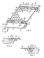
- the multi-level shield plate 10 consists of electrically conductive material, for example aluminum, and is provided with ventilation holes 12.
- the single-level screen plate 10 is supported by means of its support area 14 or 16 on a shoulder 18 or 20 of the front or rear cross rail 6 or 8. The shoulder 18 or 20 is lowered relative to the top 22 or 24 of the front or rear cross rails 6 or 8 in such a way that the tiered shield plate is approximately flush with the top 22 or 24.
- a plurality of rectangular holes 26 are arranged next to one another in a row 28 or 30 along the support area 14 or 16.
- the rectangular holes 26 are arranged next to one another with their narrow sides 32. Some of these rectangular holes 26 are provided with fastening spring 34. V-shaped springs made of electrically conductive material are provided as fastening springs 34.
- the fastening springs 34 of the rectangular row of holes 28 are in a latched position and the fastening springs 34 of the rectangular row of holes 30 are in a free position. So that the fastening springs 34 do not fall into the interior of the subrack 2 after being inserted into the rectangular holes 26 in the tiered shield plate 10, they are each provided with lateral projections 36.
- FIG. 2 shows a section along the broken line II-II.
- This sectional view shows a fastening spring 34 inserted in a rectangular hole 26.
- the arrow A indicates the direction in which the fastening spring 34 is inserted. 1 and by means of the free end of its first leg 38 on the multi-level shield plate 10.
- the multi-level shield plate 10 is supported on the shoulder 20 of the rear cross rail 8 by means of the support area 16.
- the second leg 40 of the fastening spring 34 is designed in accordance with the corresponding paragraph 20, the free end of this leg 40 being designed as a latching hook 42.
- the free end of the first leg 38 is provided with a bevel 44.
- FIG. 3 shows a section along the broken line III-III according to FIG. 1.
- This sectional view shows a fastening spring 34 latched in a rectangular hole 26.
- the fastening spring 34 moves from the position shown in FIG. 2 to the position shown.
- the latching hook 42 of the second leg 40 of the fastening spring 34 slides along a sliding surface 46 of the shoulder 18 of the front cross rail 6 until the latching position is reached.
- the latching hook 42 snaps into a notch 48 in the shoulder 18.
- the fold 44 of the first leg 38 scratches on the tiered shield plate 10, as a result of which oxide layers formed in the contact zone area are removed.
- the one-level shield plate 10 is mechanically captively connected to the cross rails 6 and 8 of the subrack 2 and, on the other hand, interference currents can be quickly diverted from the one-piece shield plate 10 to parts of the subrack 2.
Landscapes
- Engineering & Computer Science (AREA)
- Microelectronics & Electronic Packaging (AREA)
- Shielding Devices Or Components To Electric Or Magnetic Fields (AREA)
- Cooling Or The Like Of Electrical Apparatus (AREA)
- Mounting Of Printed Circuit Boards And The Like (AREA)
Priority Applications (1)
| Application Number | Priority Date | Filing Date | Title |
|---|---|---|---|
| AT88117259T ATE85182T1 (de) | 1987-10-30 | 1988-10-17 | Etagenschirmblech fuer einen baugruppentraeger. |
Applications Claiming Priority (2)
| Application Number | Priority Date | Filing Date | Title |
|---|---|---|---|
| DE8714497U DE8714497U1 (de) | 1987-10-30 | 1987-10-30 | Etagenschirmblech für einen Baugruppenträger |
| DE8714497U | 1987-10-30 |
Publications (2)
| Publication Number | Publication Date |
|---|---|
| EP0315798A1 EP0315798A1 (de) | 1989-05-17 |
| EP0315798B1 true EP0315798B1 (de) | 1993-01-27 |
Family
ID=6813608
Family Applications (1)
| Application Number | Title | Priority Date | Filing Date |
|---|---|---|---|
| EP88117259A Expired - Lifetime EP0315798B1 (de) | 1987-10-30 | 1988-10-17 | Etagenschirmblech für einen Baugruppenträger |
Country Status (7)
| Country | Link |
|---|---|
| US (1) | US4879434A (enExample) |
| EP (1) | EP0315798B1 (enExample) |
| JP (1) | JPH0639510Y2 (enExample) |
| AT (1) | ATE85182T1 (enExample) |
| CA (1) | CA1310394C (enExample) |
| DE (2) | DE8714497U1 (enExample) |
| IN (1) | IN170256B (enExample) |
Families Citing this family (33)
| Publication number | Priority date | Publication date | Assignee | Title |
|---|---|---|---|---|
| DE3928461C3 (de) * | 1989-08-29 | 1997-10-16 | Aeg Intermas Gmbh | Baugruppenträger |
| US5218518A (en) * | 1989-09-25 | 1993-06-08 | Siemens Aktiengesellschaft | Rack mountable box shaped module with conical positioning elements |
| DE8911405U1 (de) * | 1989-09-25 | 1989-11-16 | Siemens AG, 1000 Berlin und 8000 München | Etagenschirmblech für einen Baugruppenträger |
| US5307012A (en) * | 1991-12-03 | 1994-04-26 | Intel Corporation | Test substation for testing semi-conductor packages |
| DE4205478C1 (enExample) * | 1992-02-22 | 1993-07-29 | Rittal-Werk Rudolf Loh Gmbh & Co Kg, 6348 Herborn, De | |
| DE4205893C1 (en) * | 1992-02-26 | 1993-05-27 | Rittal-Werk Rudolf Loh Gmbh & Co Kg, 6348 Herborn, De | Module carrier allowing HF screening for all sides - has transverse bars with screw channels for front and rear grooves with threaded bores accepting plates with flanges |
| DE4215182C2 (de) * | 1992-05-08 | 1995-04-20 | Siemens Ag | Verfahren zur Herstellung einer elektromagnetisch dichten Halterung von zwei metallischen Bauteilen, und abgeschirmter Baugruppenträger mit derartigen Bauteilen |
| DE4237447A1 (de) * | 1992-11-06 | 1994-05-11 | Licentia Gmbh | Baugruppenträger |
| DK0627876T3 (da) * | 1993-06-01 | 1996-07-22 | Siemens Ag | Fremgangsmåde til oprettelse af en elektromagnetisk tæt fastgørelse af to metalliske dele, og afskærmede jodulrammer med sådanne dele |
| CH688907A5 (de) | 1993-08-30 | 1998-05-15 | Elma Electronic Ag | Baugruppentraeger mit Profilleisten und mit Deckplatten. |
| DE4336071A1 (de) * | 1993-10-22 | 1995-04-27 | Philips Patentverwaltung | Baugruppenträger |
| US5920984A (en) * | 1993-12-10 | 1999-07-13 | Ericsson Ge Mobile Communications Inc. | Method for the suppression of electromagnetic interference in an electronic system |
| SE503484C2 (sv) * | 1994-04-11 | 1996-06-24 | Ericsson Telefon Ab L M | Kontaktfjäder |
| JP3442398B2 (ja) * | 1995-07-15 | 2003-09-02 | リッタル−ヴェルク ルードルフ ロー ゲゼルシャフト ミット ベシュレンクテル ハフツング ウント コンパニー コマンディトゲゼルシャフト | フレーム及び被覆部材を備えた配電盤 |
| DE29604599U1 (de) | 1996-03-12 | 1997-04-10 | Siemens AG, 80333 München | Elektromagnetisch abgeschirmtes Gehäuse mit über eine Kontaktfederleiste verrastbaren metallischen Gehäuseteilen |
| DE29619565U1 (de) * | 1996-11-11 | 1997-12-18 | Siemens AG, 80333 München | Baugruppenträger für Leiterplatten mit abgeschirmter Front- und Rückseite |
| US5858509A (en) * | 1996-11-15 | 1999-01-12 | Digital Equipment Corporation | Attenuating vibrations in a mounting shelf for multiple disk drives |
| US5926366A (en) * | 1996-11-15 | 1999-07-20 | Digital Equipment Corporation | Tab and slot disk drive vibration reduction structure |
| US6018125A (en) * | 1996-11-15 | 2000-01-25 | Collins; Pat Eliot | High frequency EMI shield with air flow for electronic device enclosure |
| ATE243911T1 (de) * | 1997-03-22 | 2003-07-15 | Intermas Elcom Gmbh | Anordnung zur hochfrequenzdichten abschirmung |
| DE29806284U1 (de) | 1998-04-06 | 1998-07-23 | Knürr-Mechanik für die Elektronik AG, 81829 München | Einrichtung zur Kabelführung |
| DE29818497U1 (de) | 1998-10-16 | 1999-02-04 | Rational GmbH, 86899 Landsberg | Kühlplatte mit zumindest einem integrierten elektronischen Bauelement |
| FR2815778B1 (fr) * | 2000-10-23 | 2002-12-06 | Alstom | Dispositif de protection d'un connecteur electrique pour plaque de circuit imprime contre les perturbations electromagnetiques |
| US6900383B2 (en) * | 2001-03-19 | 2005-05-31 | Hewlett-Packard Development Company, L.P. | Board-level EMI shield that adheres to and conforms with printed circuit board component and board surfaces |
| US20050095410A1 (en) * | 2001-03-19 | 2005-05-05 | Mazurkiewicz Paul H. | Board-level conformal EMI shield having an electrically-conductive polymer coating over a thermally-conductive dielectric coating |
| DE10142497B9 (de) * | 2001-08-30 | 2005-11-17 | Siemens Ag | Gerätegehäuse eines elektronischen Gerätes zum stationären Einsatz |
| US6610922B1 (en) | 2001-12-20 | 2003-08-26 | Cisco Technology, Inc. | Apparatus for securing an electromagnetic shield in a conductive casing |
| EP2404352A4 (en) * | 2009-03-06 | 2014-06-11 | Saint Gobain Performance Plast | ELECTRICAL CONNECTOR ASSEMBLY WITH LINEAR MOTION |
| CN102356706A (zh) * | 2009-03-06 | 2012-02-15 | 美国圣戈班性能塑料公司 | 重叠的螺旋导电弹簧 |
| SG179014A1 (en) * | 2009-10-02 | 2012-04-27 | Saint Gobain Performance Plast | Modular polymeric emi/rfi seal |
| US10192846B2 (en) | 2014-11-05 | 2019-01-29 | Infineon Technologies Austria Ag | Method of inserting an electronic component into a slot in a circuit board |
| US10064287B2 (en) | 2014-11-05 | 2018-08-28 | Infineon Technologies Austria Ag | System and method of providing a semiconductor carrier and redistribution structure |
| US10553557B2 (en) * | 2014-11-05 | 2020-02-04 | Infineon Technologies Austria Ag | Electronic component, system and method |
Family Cites Families (5)
| Publication number | Priority date | Publication date | Assignee | Title |
|---|---|---|---|---|
| GB802586A (en) * | 1956-02-17 | 1958-10-08 | Ft Products Ltd | Improvements relating to fasteners |
| US3340587A (en) * | 1965-11-26 | 1967-09-12 | Herbert K Beyer | Method of fabricating shielding enclosures |
| US3502784A (en) * | 1968-09-11 | 1970-03-24 | Scanbe Mfg Corp | Gasket |
| US4114848A (en) * | 1975-01-03 | 1978-09-19 | La Telemecanique Electrique | Mounting plate |
| US4716493A (en) * | 1985-05-21 | 1987-12-29 | Philip Zelkowitz | Electronic instrument housing |
-
1987
- 1987-10-30 DE DE8714497U patent/DE8714497U1/de not_active Expired
-
1988
- 1988-09-29 IN IN809/CAL/88A patent/IN170256B/en unknown
- 1988-10-11 US US07/256,047 patent/US4879434A/en not_active Expired - Fee Related
- 1988-10-17 EP EP88117259A patent/EP0315798B1/de not_active Expired - Lifetime
- 1988-10-17 AT AT88117259T patent/ATE85182T1/de not_active IP Right Cessation
- 1988-10-17 DE DE8888117259T patent/DE3877900D1/de not_active Expired - Fee Related
- 1988-10-28 CA CA000581562A patent/CA1310394C/en not_active Expired - Lifetime
- 1988-10-28 JP JP1988141877U patent/JPH0639510Y2/ja not_active Expired - Lifetime
Also Published As
| Publication number | Publication date |
|---|---|
| DE3877900D1 (de) | 1993-03-11 |
| EP0315798A1 (de) | 1989-05-17 |
| JPH0639510Y2 (ja) | 1994-10-12 |
| DE8714497U1 (de) | 1987-12-10 |
| US4879434A (en) | 1989-11-07 |
| CA1310394C (en) | 1992-11-17 |
| JPH0173990U (enExample) | 1989-05-18 |
| ATE85182T1 (de) | 1993-02-15 |
| IN170256B (enExample) | 1992-03-07 |
Similar Documents
| Publication | Publication Date | Title |
|---|---|---|
| EP0315798B1 (de) | Etagenschirmblech für einen Baugruppenträger | |
| DE69508396T2 (de) | Schieneneinheit | |
| DE2833313C2 (de) | Klemmenblock für gedruckte Schaltungen | |
| DE2701518A1 (de) | Mit eingebautem umformer ausgestattete haltevorrichtung fuer leuchtstoffroehren, insbesondere zur beleuchtung von fahrzeugen | |
| EP0105150B1 (de) | Führungsschiene für elektronische Baugruppenträger | |
| DE69103362T2 (de) | Beförderungsschutz- und Einfügungsgerät für mehradrige Kabel. | |
| EP0838987B1 (de) | Baugruppenträger | |
| EP0447942B1 (de) | Kontaktleiste für eine störstrahlungsdichte Verbindung benachbarter metallischer Wandelemente | |
| DE8803544U1 (de) | Baugruppenträger mit abgeschirmten Steckbaugruppen | |
| DE9309768U1 (de) | Kontaktiereinrichtung für ein Leiterplattengestell einer Galvanikanlage | |
| EP0116909B1 (de) | Halterung einer absenkbaren Leuchtenabdeckung | |
| EP0838989B1 (de) | Abgeschirmter Baugruppenträger | |
| DE3634462C2 (enExample) | ||
| DE9209519U1 (de) | HF-dichter Baugruppenträger | |
| EP0148334B1 (de) | Anordnung zur Halterung von Zubehör an einer Leuchtenwand | |
| DE3330984A1 (de) | Vorrichtung zum elektrisch leitenden verbinden von zwei oder mehreren elektrisch leitenden stiften | |
| DE29802727U1 (de) | Anschlußleiste und auf eine Anschlußleiste aufsteckbares Überspannungsschutzmagazin | |
| DE29720511U1 (de) | Einbaugehäuse für Leiterplatten und Elektronikbausteine | |
| DE3014172C2 (de) | Elektrische Verbindungseinrichtung | |
| DE19833248A1 (de) | Vorrichtung zum Führen und Massekontaktieren von Leiterplatten | |
| DE3200729C2 (de) | Einrichtung zur Befestigung von Leiterplatten in einem Trägerrahmen | |
| DE102012101829A1 (de) | Induktionskochfeld | |
| DE2834728A1 (de) | Anordnung zum anschluss von in rahmenartigen baugruppentraegern einschiebbaren elektronischen baugruppen | |
| DE19523257C1 (de) | Baugruppenträger | |
| DE3112505C2 (de) | Rahmen für einschiebbare elektrische Baugruppen |
Legal Events
| Date | Code | Title | Description |
|---|---|---|---|
| PUAI | Public reference made under article 153(3) epc to a published international application that has entered the european phase |
Free format text: ORIGINAL CODE: 0009012 |
|
| AK | Designated contracting states |
Kind code of ref document: A1 Designated state(s): AT CH DE FR GB IT LI NL SE |
|
| 17P | Request for examination filed |
Effective date: 19890608 |
|
| 17Q | First examination report despatched |
Effective date: 19910823 |
|
| GRAA | (expected) grant |
Free format text: ORIGINAL CODE: 0009210 |
|
| AK | Designated contracting states |
Kind code of ref document: B1 Designated state(s): AT CH DE FR GB IT LI NL SE |
|
| REF | Corresponds to: |
Ref document number: 85182 Country of ref document: AT Date of ref document: 19930215 Kind code of ref document: T |
|
| REF | Corresponds to: |
Ref document number: 3877900 Country of ref document: DE Date of ref document: 19930311 |
|
| ET | Fr: translation filed | ||
| ITF | It: translation for a ep patent filed | ||
| GBT | Gb: translation of ep patent filed (gb section 77(6)(a)/1977) |
Effective date: 19930401 |
|
| PLBE | No opposition filed within time limit |
Free format text: ORIGINAL CODE: 0009261 |
|
| STAA | Information on the status of an ep patent application or granted ep patent |
Free format text: STATUS: NO OPPOSITION FILED WITHIN TIME LIMIT |
|
| 26N | No opposition filed | ||
| EAL | Se: european patent in force in sweden |
Ref document number: 88117259.7 |
|
| PGFP | Annual fee paid to national office [announced via postgrant information from national office to epo] |
Ref country code: DE Payment date: 19971218 Year of fee payment: 10 |
|
| PGFP | Annual fee paid to national office [announced via postgrant information from national office to epo] |
Ref country code: CH Payment date: 19980120 Year of fee payment: 10 |
|
| PGFP | Annual fee paid to national office [announced via postgrant information from national office to epo] |
Ref country code: GB Payment date: 19980909 Year of fee payment: 11 |
|
| PGFP | Annual fee paid to national office [announced via postgrant information from national office to epo] |
Ref country code: AT Payment date: 19980929 Year of fee payment: 11 |
|
| PGFP | Annual fee paid to national office [announced via postgrant information from national office to epo] |
Ref country code: FR Payment date: 19981023 Year of fee payment: 11 |
|
| PGFP | Annual fee paid to national office [announced via postgrant information from national office to epo] |
Ref country code: SE Payment date: 19981027 Year of fee payment: 11 |
|
| PGFP | Annual fee paid to national office [announced via postgrant information from national office to epo] |
Ref country code: NL Payment date: 19981030 Year of fee payment: 11 |
|
| PG25 | Lapsed in a contracting state [announced via postgrant information from national office to epo] |
Ref country code: LI Free format text: LAPSE BECAUSE OF NON-PAYMENT OF DUE FEES Effective date: 19981031 Ref country code: CH Free format text: LAPSE BECAUSE OF NON-PAYMENT OF DUE FEES Effective date: 19981031 |
|
| REG | Reference to a national code |
Ref country code: CH Ref legal event code: PL |
|
| PG25 | Lapsed in a contracting state [announced via postgrant information from national office to epo] |
Ref country code: DE Free format text: LAPSE BECAUSE OF NON-PAYMENT OF DUE FEES Effective date: 19990803 |
|
| PG25 | Lapsed in a contracting state [announced via postgrant information from national office to epo] |
Ref country code: GB Free format text: LAPSE BECAUSE OF NON-PAYMENT OF DUE FEES Effective date: 19991017 Ref country code: AT Free format text: LAPSE BECAUSE OF NON-PAYMENT OF DUE FEES Effective date: 19991017 |
|
| PG25 | Lapsed in a contracting state [announced via postgrant information from national office to epo] |
Ref country code: SE Free format text: THE PATENT HAS BEEN ANNULLED BY A DECISION OF A NATIONAL AUTHORITY Effective date: 19991030 |
|
| PG25 | Lapsed in a contracting state [announced via postgrant information from national office to epo] |
Ref country code: NL Free format text: LAPSE BECAUSE OF NON-PAYMENT OF DUE FEES Effective date: 20000501 |
|
| GBPC | Gb: european patent ceased through non-payment of renewal fee |
Effective date: 19991017 |
|
| EUG | Se: european patent has lapsed |
Ref document number: 88117259.7 |
|
| PG25 | Lapsed in a contracting state [announced via postgrant information from national office to epo] |
Ref country code: FR Free format text: LAPSE BECAUSE OF NON-PAYMENT OF DUE FEES Effective date: 20000630 |
|
| NLV4 | Nl: lapsed or anulled due to non-payment of the annual fee |
Effective date: 20000501 |
|
| REG | Reference to a national code |
Ref country code: FR Ref legal event code: ST |
|
| PG25 | Lapsed in a contracting state [announced via postgrant information from national office to epo] |
Ref country code: IT Free format text: LAPSE BECAUSE OF NON-PAYMENT OF DUE FEES;WARNING: LAPSES OF ITALIAN PATENTS WITH EFFECTIVE DATE BEFORE 2007 MAY HAVE OCCURRED AT ANY TIME BEFORE 2007. THE CORRECT EFFECTIVE DATE MAY BE DIFFERENT FROM THE ONE RECORDED. Effective date: 20051017 |