EP0308178A2 - Schwungrad mit Torsionsschwingungsdämpfer - Google Patents
Schwungrad mit Torsionsschwingungsdämpfer Download PDFInfo
- Publication number
- EP0308178A2 EP0308178A2 EP88308457A EP88308457A EP0308178A2 EP 0308178 A2 EP0308178 A2 EP 0308178A2 EP 88308457 A EP88308457 A EP 88308457A EP 88308457 A EP88308457 A EP 88308457A EP 0308178 A2 EP0308178 A2 EP 0308178A2
- Authority
- EP
- European Patent Office
- Prior art keywords
- spring
- flywheel
- driving
- spring mechanism
- flywheel device
- Prior art date
- Legal status (The legal status is an assumption and is not a legal conclusion. Google has not performed a legal analysis and makes no representation as to the accuracy of the status listed.)
- Granted
Links
Images


Classifications
-
- F—MECHANICAL ENGINEERING; LIGHTING; HEATING; WEAPONS; BLASTING
- F16—ENGINEERING ELEMENTS AND UNITS; GENERAL MEASURES FOR PRODUCING AND MAINTAINING EFFECTIVE FUNCTIONING OF MACHINES OR INSTALLATIONS; THERMAL INSULATION IN GENERAL
- F16F—SPRINGS; SHOCK-ABSORBERS; MEANS FOR DAMPING VIBRATION
- F16F15/00—Suppression of vibrations in systems; Means or arrangements for avoiding or reducing out-of-balance forces, e.g. due to motion
- F16F15/10—Suppression of vibrations in rotating systems by making use of members moving with the system
- F16F15/12—Suppression of vibrations in rotating systems by making use of members moving with the system using elastic members or friction-damping members, e.g. between a rotating shaft and a gyratory mass mounted thereon
- F16F15/131—Suppression of vibrations in rotating systems by making use of members moving with the system using elastic members or friction-damping members, e.g. between a rotating shaft and a gyratory mass mounted thereon the rotating system comprising two or more gyratory masses
- F16F15/139—Suppression of vibrations in rotating systems by making use of members moving with the system using elastic members or friction-damping members, e.g. between a rotating shaft and a gyratory mass mounted thereon the rotating system comprising two or more gyratory masses characterised by friction-damping means
-
- F—MECHANICAL ENGINEERING; LIGHTING; HEATING; WEAPONS; BLASTING
- F16—ENGINEERING ELEMENTS AND UNITS; GENERAL MEASURES FOR PRODUCING AND MAINTAINING EFFECTIVE FUNCTIONING OF MACHINES OR INSTALLATIONS; THERMAL INSULATION IN GENERAL
- F16F—SPRINGS; SHOCK-ABSORBERS; MEANS FOR DAMPING VIBRATION
- F16F15/00—Suppression of vibrations in systems; Means or arrangements for avoiding or reducing out-of-balance forces, e.g. due to motion
- F16F15/10—Suppression of vibrations in rotating systems by making use of members moving with the system
- F16F15/12—Suppression of vibrations in rotating systems by making use of members moving with the system using elastic members or friction-damping members, e.g. between a rotating shaft and a gyratory mass mounted thereon
- F16F15/131—Suppression of vibrations in rotating systems by making use of members moving with the system using elastic members or friction-damping members, e.g. between a rotating shaft and a gyratory mass mounted thereon the rotating system comprising two or more gyratory masses
- F16F15/133—Suppression of vibrations in rotating systems by making use of members moving with the system using elastic members or friction-damping members, e.g. between a rotating shaft and a gyratory mass mounted thereon the rotating system comprising two or more gyratory masses using springs as elastic members, e.g. metallic springs
- F16F15/134—Wound springs
- F16F15/13469—Combinations of dampers, e.g. with multiple plates, multiple spring sets, i.e. complex configurations
- F16F15/13476—Combinations of dampers, e.g. with multiple plates, multiple spring sets, i.e. complex configurations resulting in a staged spring characteristic, e.g. with multiple intermediate plates
- F16F15/13484—Combinations of dampers, e.g. with multiple plates, multiple spring sets, i.e. complex configurations resulting in a staged spring characteristic, e.g. with multiple intermediate plates acting on multiple sets of springs
- F16F15/13492—Combinations of dampers, e.g. with multiple plates, multiple spring sets, i.e. complex configurations resulting in a staged spring characteristic, e.g. with multiple intermediate plates acting on multiple sets of springs the sets of springs being arranged at substantially the same radius
Definitions
- the present invention relates to flywheels and, more particularly, to a flywheel that can change vibrational behavior between two kinds of characteristics, thereby suppressing resonance and improving torque variation absorbing effects.
- Flywheels which comprise driving and driven side flywheels, a spring mechanism for connecting the driving and driven side flywheels, and a friction mechanism are well known, as shown, for example, in U.S. Patent Nos. 4,468,207, 4,274,524, 4,351,168, 2,042,570, 4,445,876, 2,729,079, 2,437,537, 4,663,983, 4,220,233, 4,002,043; GB-A-2,000,257; DE-A-2,926,012; Automotive Engineering, vol.
- the prior art flywheels have a single kind of vibrational characteristic generated by a single kind of spring mechanism, even if the spring mechanism itself includes a plurality of coil springs arranged in series or in parallel with each other.
- the single kind of vibrational characteristic causes the flywheel to have a single first mode resonance speed throughout the entire range of engine speeds.
- the resonance speed is usually set lower than the idling speed of the engine.
- a continuously sliding friction mechanism (often called as a hysteresis mechanism) which continuously slides through the entire range of the engine speeds is disposed between the driving and driven side flywheels.
- An object of the invention is to provide a flywheel device with two kinds of vibrational characteristics having different resonance speeds so that the vibrational system of the flywheel device can momentarily change its vibrational characteristic from one characteristic to the other characteristic while passing through the resonance speed of the one characteristic of the vibrational system to thereby suppress the resonance during passing through the resonance speed of the one characteristic without using a continuously sliding friction mechanism.
- Another object of the invention is to provide a flywheel device which improves its torque variation absorbing effect to a great extent at a standard range of engine speeds because it does not use a continuously sliding friction mechanism.
- a flywheel device in accordance with the present invention which comprises: a driving side flywheel; a driven side flywheel arranged coaxial with respect to the driving side flywheel and rotatable relative to the driving side flywheel; a first spring mechanism directly connecting the driving and driven side flywheels with a predetermined torsional angular gap; and a second spring mechanism provided in parallel to the first spring mechanism as a spring arrangement so as to connect the driving and driven side flywheels via a friction mechanism which is arranged in series with the second spring mechanism as a vibrational system.
- the first spring mechanism when a torsional angle generated between the driving and driven side flywheels is less than or equal to the predetermined angular gap, for,example, ⁇ P between the first spring mechanism and the driven plate, the first spring mechanism does not operate and only the second spring mechanism operates.
- the spring constant of the vibrational system of the flywheel device is equal to the synthetic spring constant K1 of the second spring mechanism.
- the first spring mechanism when the torsional angle generated between the driving and driven side flywheels exceeds the angular gap ⁇ P , the first spring mechanism operates and the friction mechanism begins to slip. The slippage of the friction mechanism makes the second spring mechanism substantially ineffective and, as a result, a spring constant of the vibrational system of the flywheel device momentarily changes to the synthetic spring constant K of the first spring mechanism.
- the rotational speed of the flywheel device passes through the resonance speed of the system having the spring constant K1 of the second spring mechanism and, when the rotational speed of the flywheel device approaches the resonance speed of the characteristic of spring constant K1, the amplitude of relative rotation between the driving and driven side flywheels will increase.
- the friction mechanism begins to slip to make the second spring mechanism ineffective and the first spring mechanism begins to operate.
- the vibrational system of the flywheel device has a synthetic spring constant K of the first spring mechanism which naturally differs from the synthetic spring constant K1 of the second spring mechanism.
- the vibrational system changes its characteristic from the characteristic of spring constant K1 to the characteristic of spring constant K while passing through the resonance speed of the characteristic of spring constant K1 to thereby greatly suppress the resonance.
- the rotational speed of the flywheel device has passed through the resonance speed of the characteristic of spring constant K1 and changes from the resonance speed, the amplitude of relative rotation gradually decreases.
- the friction mechanism ceases slipping and the second spring mechanism again operates. This means that the flywheel device has no notable resonance speed throughout the entire range of engine speeds and that the flywheel device can pass through the resonance speed without being greatly amplified in vibration.
- FIG. 3 which illustrates the vibrational system of the flywheel device according to the first embodiment of the present invention
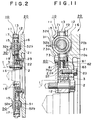
- the flywheel device is generally divided into a driving side flywheel 10 defining a moment of inertia I1 and a driven side flywheel 20 defining a moment of inertia I2.
- the two inertia moments I1 and I2 are compatible.
- Driving side flywheel 10 and driven side flywheel 20 are arranged coaxially with respect to each other and rotatable relative to each other.
- Driving side flywheel 10 and driven side flywheel 20 are connected to each other in the rotational direction via a first spring mechanism 30 which directly connects driving side flywheel 10 and driven side flywheel 20 with a first predetermined torsional angular gap ⁇ P .
- Diriving side flywheel 10 and driven side flywheel 20 are also connected by a second spring mechanism 40 which is disposed in parallel to first spring mechanism 30 and which connects driving side flywheel 10 and driven side flywheel 20 via a friction mechanism 60.
- Friction mechanism 60 is arranged in series with second spring mechanism 40 as a vibrational system.
- first and second spring mechanisms 30 and 40 K and K1
- a predetermined frictional force of friction mechanism 60 Fr
- the spring constant K of first spring mechanism 30 is selected so as to be less than the spring constant K1 of second spring mechanism 40.
- the ratio of the spring constant K1 of second spring mechanism 40 to the spring constant K of first spring mechanism 30 is 3 - 4.
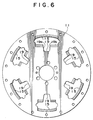
- the first spring mechanism 30 comprises at least one first coil spring 31 and spring seats 32 disposed at each end of first coil spring 31.
- each spring seat 32 includes a seat portion 32a constructed of hard synthetic resin and a cushion 32b constructed of elastic rubber. Cushions 32b of spring seats 32 disposed at each end of first coil spring 31 face each other so that when first coil spring 31 is greatly compressed, the facing cushions 32b are brought into contact with each other and are deformed.
- Second spring mechanism 40 comprises at least one second coil spring 41 and spring seats 42 disposed at each end of second coil spring 41.
- Each spring seat 42 includes a seat portion 42a constructed of hard synthetic resin and a cushion 42b constructed of elastic rubber. Cushions 42b of spring seats 42 disposed at each end of each second coil spring 41 face each other so that when second coil spring 41 is greatly compressed, the facing cushions 42b are brought into contact with each other and are deformed.
- the flywheel device may further comprise a third spring mechanism 50 connecting driving and driven side flywheels 10 and 20 with a second predetermined torsional angular gap ⁇ R larger than the first torsional angular gap ⁇ P with which first spring mechanism 30 connects the driving and driven side flywheels 10 and 20.
- Third spring mechanism 50 has a synthetic spring constant K2.
- third spring mechanism 50 comprises at least one third coil spring 51 and spring seats 52 disposed at each end of each third coil spring 51.
- Each spring seat 52 includes a seat portion 52a constructed of hard synthetic resin and a cushion 52b constructed of elastic rubber. Cushions 52b disposed at each end of each third coil spring 51 face each other so that when the third coil spring 51 is greatly compressed, the facing cushions 52b are brought into contact with each and are deformed.
- first spring mechanism 30 has one first coil spring 31 and second spring mechanism 40 has three second coil springs 41.
- third spring mechanism 50 has two third coil springs 51.
- These spring mechanisms are arranged at a substantially common circumference and extend in a circumferential direction of the flywheel device. These spring mechanisms compose torsional dampers of the flywheel device which dampen relative rotations between driving and driven side flywheels 10 and 20 through vibration suppressing effects due to the springs.
- Synthetic spring constants K, K1 and K2 of first, second and third spring mechanisms 30, 40 and 50, respectively are determined as synthetic spring constants of first, second and third coil springs 31, 41 and 51, respectively.
- each second coil spring 41 has a spring constant K1/3 so that the parallel combination of the three second coil springs 41 causes the synthetic spring constant K1 of second spring mechanism 40.
- friction mechanism 60 comprises a thrust lining 61 constructed of abrasive material, a thrust plate 62, and a cone spring 63 for generating the predetermined frictional force Fr of friction mechanism 60.
- Thrust lining 61, thrust plate 62 and cone spring 63 are disposed between driving and driven side flywheels 10 and 20 in the axial direction of the flywheel device.
- Thrust plate 62 is an annular member having a plurality of protrusions protruding radially outward where slots 62a are formed. Slots 62a engage with rivets connecting control plate elements of a control plate so as to rotate together with the control plate, as described more fully below.
- driving side flywheel 10 is coupled to a crankshaft 1 by bolts 2.
- Driving side flywheel 10 comprises a ring gear 13, an inner ring 14 disposed radially inside and radially spaced from ring gear 13, and a pair of driving plates 11 and 12 fixedly coupled to ring gear 13 by rivets 17.
- Inner ring 14 is fixedly coupled to one of the driving plates 11 by screws 18 or bolts.
- one of the driving plates 11 has circumferentially elongated openings 15. Ends of elongated openings 15 detachably engage with the first, second and third spring mechanisms 30, 40 and 50. As shown in FIG. 7, the other of the driving plates 12 has circumferentially prolonged slots 16. Ends of elongated slots 16 detachably engage with the first, second and third spring mechanisms 30, 40 and 50.
- driven side flywheel 20 is supported by inner ring 14 of driving side flywheel 10 via a bearing 3 so as to be rotatable relative to driving side flywheel 10.
- side flywheel 20 is coupled to a power train of a vehicle via a clutch mechanism (not shown).
- Driven side flywheel 20 comprises a flywheel body 21 arranged so as to oppose driving side flywheel 10 in the axial direction of the flywheel device and a driven plate 22 fixedly coupled to the flywheel body 21 by a bolt 23.
- driven plate 22 comprises an annular portion 22a and a plurality of arms 22b extending radially outwardly from annular portion 22a.
- Annular portion 22a of driving plate 22 slidably engages friction mechanism 60 and arms 22b of driven plate 22 detachably engage first spring mechanism 30 with the predetermined torsional angular gap ⁇ P .
- Arms 22b of driven plate 22 also detachably engage third spring mechanism 50 with the second torsional angular gap ⁇ R larger than the angular gap ⁇ P with which first spring mechanism 30 connects driving and driven side flywheels 10 and 20.
- the flywheel device further comprises a control plate 70 arranged between driving and driven side flywheels 10 and 20 as a vibrational system so as to be rotatable relative to driving and driven side flywheels 10 and 20 and so as to connect second spring mechanism 40 and friction mechanism 60.
- control plate 70 comprises a pair of control plate elements 71 and 72 disposed substantially in parallel to each other and coupled to each other by a rivet 73.
- Control plate 70 includes an annular portion 70a and a plurality of arms 70b extending radially outwardly from annular portion 70a. Annular portion 70a of control plate 70 slidably engages friction mechanism 60 and arms 70b of control plate 70 detachably engage second spring mechanism 40.
- the flywheel device operates according to the torsional angle-torque characteristic illustrated in FIG. 4 and according to the engine speeds-torque transmittance rate characteristic illustrated in FIG. 5.
- the vibrational system of the flywheel device generally has two vibrational characteristics, that is, a characteristic (K characteristic) having the synthetic spring constant K of first spring mechanism 30 and a characteristic (K1 characteristic) having the synthetic spring constant K1 of second spring mechanism 40.
- the two characteristics have resonance speeds different from each other.
- relative rotation that is, the torsional angle between driving and driven side flywheels 10 and 20 is less than the predetermined angular gap ⁇ P , friction mechanism 60 does not slip and the flywheel device operates according to the K1 characteristic.
- the K characteristic has a resonance speed different from the K1 characteristic and the vibrational system having changed its characteristic to the K characteristic is no longer amplified in vibration while passing through the resonance speed of the K1 characteristic.
- the engine speed changes from the resonance speed of the K1 characteristic being accompanied with a slippage of friction mechanism 60
- the amplitude of vibration decreases and the torsional angle between driving and driven side flywheels 10 and 20 decreases to a torsional angle less than the predetermined angular gap ⁇ P .
- friction mechanism 60 stops slipping to make second spring mechanism 40 effective and first spring mechanism 30 stops operating. In this way, the flywheel device again operates according to the original characteristic K1.
- friction mechanism 60 slips only momentarily while passing through the resonance speed of the K1 characteristic for the purpose of changing the resonance speed of the vibrational system from the resonance speed of the K1 characteristic to the resonance speed of the K characteristic to thereby suppress resonance.
- the resonance suppression due to a change in spring constant is usually more effective than the resonance suppression due to a continuously sliding friction mechanism, and therefore, an improvement in resonance suppression is also obtained according to the present invention as shown in FIG. 5.
- the flywheel device of the second embodiment has substantially the same elements as those of the flywheel device according to the first embodiment except for the friction mechanism forcibly sliding members.
- Thefore a discussion of the portions of the flywheel device according to the second embodiment which are the same as those of the flywheel device according to the first embodiment will be omitted, and only the elements different from those of the first embodiment will be explained below.
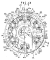
- the flywheel device further comprises members H, provided against a torque transmitting path comprising the series combination of second spring mechanism 40 and friction mechanism 60, for forcibly sliding friction mechanism 60 at torsional angles larger than the torsional angle ⁇ P of the predetermined angular gap with which first spring mechanism 30 connects driving and driven side flywheels 10 and 20.
- rivet 73 connecting control plate elements 71 and 72 of control plate 70 extends in the axial direction of the flywheel device and further extends from one control plate element 71 toward one driving plate 11 to form a rivet head 73a.
- Rivet head 73a may be integral with rivet 73 itself as shown in FIG.
- one driving plate 11 has a radially extending slot 19 which opens to circumferentially elongated opening 15.
- Radially extending slot 19 is defined by sides 19a and 19b such that a torsional angular gap equal in gap size to the angular gap ⁇ P is provided between each side 19a, 19b of radially extending slot 19 and rivet head 73a, as shown in FIG. 13.
- the members H for forcibly sliding friction mechanism 60 comprise rivet head 73a and sides 19a and 19b of radially extending slot 19 formed in driving plate 11.
- FIG. 14 illustrates the vibrational system of the second embodiment where the members H for forcibly sliding friction mechanism 60 are added in comparison with the vibrational system of the first embodiment illustrated in FIG. 3.
- flywheel device according to the third embodiment of the present invention will be discussed with reference to FIGS. 18 and 19.
- the flywheel device of the third embodiment has substantially the same elements as those of the flywheel device according to the second embodiment except for the second spring mechanism forcibly operating member.
- Thefore a discussion of the portions of the flywheel device according to the third embodiment which are the same as those of the flywheel devices according to the first and second embodiments will be omitted and only the elements different from those of the first and second embodiments will be explained below.
- the flywheel device further comprises a member L, provided in a torque transmitting path comprising the series combination of second spring mechanism 40 and friction mechanism 60, for forcibly and again operating second spring mechanism 40 at torsional angles not less than a predetermined second torsional angle ⁇ R which is larger than the torsional angle ⁇ P .
- each arm 22b of driven plate 22 has sides 24 and 25.
- a predetermined torsional angular gap with a torsional angle equal to the difference between the second predetermined torsional angle ⁇ R and the torsional angle ⁇ P is provided between second spring mechanism 40 and the side 24, 25 of the arm 22b which circumferentially opposes second spring mechanim 40.
- Member L comprises sides 24 and 25 of arms 22b of driven plate 22.
- the torsional angle of the second angular gap ⁇ R provided between third spring mechanism 50 and driven side flywheel 20 is equal to the angle provided between side 24, 25 of arm 22b of driven plate 22 and second spring mechanism 40.
- second spring mechanism 40 is again made effective in operation at range C of FIG. 4, even if friction mechanism 60 is slipping, and all spring mechanisms 30 and 40 (and 50 when third spring mechanism 50 is provided) operate effectively at range C of FIG. 4. As a result, a high torque can be transmitted at a large torsional angle range such as range C.
- the flywheel device according to the third embodiment can be used for a flywheel device for receiving a large torque.
- the torque variation absorbing effect is improved at a standard range of engine speeds because no slippage of friction mechanism 60 occurs at the standard range of engine speeds.
- the flywheel device has no notable resonance speed throughout the entire range of engine speeds because the flywheel device has two characteristics and changes its characteristic from the K1 characteristic to the K characteristic while passing through the resonance speed of the K1 characteristic.
- first spring mechanism 30 is only needed to operate at torsional angles larger than the predetermined torsional angle ⁇ P , first spring mechanism 30 can be made smaller than second spring mechanism 40 and a space for providing first spring mechanism 30 can be made small. This enables compact design of the flywheel device and easily provides a space for mounting a third spring mechanism 50 when a third spring mechanism 50 is provided. Provision of third spring mechanism 50 increases the torque transmitting capacity of the flywheel device.
Applications Claiming Priority (6)
| Application Number | Priority Date | Filing Date | Title |
|---|---|---|---|
| JP140916/87 | 1987-06-05 | ||
| JP13936787U JPH0620916Y2 (ja) | 1987-09-14 | 1987-09-14 | トーショナルダンパ付フライホイール |
| JP139367/87 | 1987-09-14 | ||
| JP140058/87 | 1987-09-16 | ||
| JP14005887U JPH0620920Y2 (ja) | 1987-09-16 | 1987-09-16 | トーショナルダンパ付フライホイール |
| JP14091687U JPH0620917Y2 (ja) | 1987-09-17 | 1987-09-17 | ト−ショナルダンパ付フライホイ−ル |
Publications (3)
| Publication Number | Publication Date |
|---|---|
| EP0308178A2 true EP0308178A2 (de) | 1989-03-22 |
| EP0308178A3 EP0308178A3 (en) | 1989-08-16 |
| EP0308178B1 EP0308178B1 (de) | 1992-12-09 |
Family
ID=27317851
Family Applications (1)
| Application Number | Title | Priority Date | Filing Date |
|---|---|---|---|
| EP88308457A Expired EP0308178B1 (de) | 1987-09-14 | 1988-09-13 | Schwungrad mit Torsionsschwingungsdämpfer |
Country Status (3)
| Country | Link |
|---|---|
| US (1) | US4950205A (de) |
| EP (1) | EP0308178B1 (de) |
| DE (1) | DE3876559T2 (de) |
Cited By (8)
| Publication number | Priority date | Publication date | Assignee | Title |
|---|---|---|---|---|
| EP0339805A2 (de) * | 1988-04-01 | 1989-11-02 | Toyota Jidosha Kabushiki Kaisha | Schwungrad vom Typ mit einem Drehschwingungsdämpfer mit einem Dämpfungsmechanismus mit Flüssigkeit |
| US5156067A (en) * | 1988-04-01 | 1992-10-20 | Toyota Jidosha Kabushiki Kaisha | Torsional damper type flywheel device |
| US5269199A (en) * | 1988-04-01 | 1993-12-14 | Toyota Jidosha Kabushiki Kaisha | Torional damper type flywheel device |
| FR2714440A1 (fr) * | 1993-12-23 | 1995-06-30 | Valeo | Dispositif amortisseur de torsion, notamment pour véhicule automobile. |
| FR2732425A1 (fr) * | 1995-03-31 | 1996-10-04 | Valeo | Dispositif amortisseur de torsion a sieges basculants de structure composite pour les ressorts, notamment pour vehicule automobile |
| FR2732426A1 (fr) * | 1995-03-31 | 1996-10-04 | Valeo | Dispositif amortisseur de torsion a sieges metalliques pour les ressorts, notamment pour vehicule automobile |
| WO2010043301A1 (en) * | 2008-10-17 | 2010-04-22 | Luk Lamellen Und Kupplungsbau Beteiligungs Kg | Double path torsional damper |
| EP2711576A1 (de) * | 2012-09-24 | 2014-03-26 | Valeo Embrayages | Momentübertragungsvorrichtung für ein Fahrzeug |
Families Citing this family (16)
| Publication number | Priority date | Publication date | Assignee | Title |
|---|---|---|---|---|
| EP0361669B1 (de) * | 1988-09-28 | 1993-05-12 | Toyota Jidosha Kabushiki Kaisha | Schwungradvorrichtung mit Torsionsdämpfer |
| JPH0248637U (de) * | 1988-09-30 | 1990-04-04 | ||
| US5111714A (en) * | 1989-09-11 | 1992-05-12 | Toyota Jidosha Kabushiki Kaisha | Torsional damper type flywheel device |
| FR2698934B1 (fr) * | 1992-12-09 | 1995-01-20 | Valeo | Amortisseur de torsion, notamment pour véhicule automobile. |
| FR2698933B1 (fr) * | 1992-12-09 | 1995-03-10 | Valeo | Amortisseur de torsion, notamment pour véhicule automobile. |
| JP3262241B2 (ja) * | 1993-09-07 | 2002-03-04 | ヴァレオユニシアトランスミッション株式会社 | トーショナルダンパの振動減衰装置 |
| FR2714948B1 (fr) * | 1993-11-15 | 1996-03-08 | Valeo | Volant amortisseur notamment pour véhicule automobile. |
| DE69507091T3 (de) * | 1994-07-29 | 2004-07-22 | Aisin Seiki K.K., Kariya | Drehmoment-absorbierende Scheibe |
| JPH1182582A (ja) * | 1997-09-08 | 1999-03-26 | Exedy Corp | ロックアップダンパー用コイルスプリング組立体 |
| JP2003278836A (ja) * | 2002-03-26 | 2003-10-02 | Aisin Seiki Co Ltd | トルク変動吸収装置 |
| DE102004040886A1 (de) * | 2004-08-24 | 2006-03-02 | Volkswagen Ag | Bedienvorrichtung für ein Kraftfahrzeug |
| US10010983B2 (en) | 2008-03-07 | 2018-07-03 | Fatigue Technology, Inc. | Expandable member with wave inhibitor and methods of using the same |
| DE102008031489B4 (de) * | 2008-07-03 | 2010-06-02 | Saf-Holland Gmbh | Einrichtung zur Lagerung einer Nockenwelle |
| US8523685B2 (en) * | 2010-09-24 | 2013-09-03 | Aisin Seiki Kabushiki Kaisha | Torque fluctuation absorber |
| JP5789944B2 (ja) * | 2010-09-24 | 2015-10-07 | アイシン精機株式会社 | トルク変動吸収装置 |
| KR101284342B1 (ko) * | 2011-12-09 | 2013-07-08 | 현대자동차주식회사 | 토크 컨버터의 댐퍼 클러치 |
Citations (4)
| Publication number | Priority date | Publication date | Assignee | Title |
|---|---|---|---|---|
| GB2163524A (en) * | 1984-08-18 | 1986-02-26 | Daimler Benz Ag | A device for reducing the transmission of vibrations |
| FR2593252A1 (fr) * | 1986-01-22 | 1987-07-24 | Valeo | Volant amortisseur pour transmission, notamment pour vehicule automobile |
| GB2186344A (en) * | 1986-02-06 | 1987-08-12 | Aisin Seiki | Torque variation absorbing devices |
| EP0259173A2 (de) * | 1986-09-05 | 1988-03-09 | Toyota Jidosha Kabushiki Kaisha | Schwungrad mit einem Drehmomentschwingungsdämpfer |
Family Cites Families (33)
| Publication number | Priority date | Publication date | Assignee | Title |
|---|---|---|---|---|
| US2042570A (en) * | 1935-01-28 | 1936-06-02 | Ernest E Wemp | Vibration dampener |
| US2437537A (en) * | 1946-02-27 | 1948-03-09 | Ira Saks | Clutch plate |
| US3266271A (en) * | 1964-06-08 | 1966-08-16 | Borg Warner | Vibration dampener assembly |
| US4002043A (en) * | 1973-07-10 | 1977-01-11 | Toyota Jidosha Kogyo Kabushiki Kaisha | Apparatus for absorbing torque fluctuations produced by an internal combustion engine |
| JPS547008A (en) * | 1977-06-16 | 1979-01-19 | Aisin Seiki Co Ltd | Torsion-damer-added-flywheel |
| JPS601497B2 (ja) * | 1978-08-03 | 1985-01-16 | アイシン精機株式会社 | 回転トルク伝達装置 |
| JPS6038577B2 (ja) * | 1979-03-30 | 1985-09-02 | トヨタ自動車株式会社 | 車輛用内燃機関の回転振動吸収装置 |
| JPS5932993B2 (ja) * | 1979-06-25 | 1984-08-13 | 株式会社明電舎 | 多相インバ−タの電圧制御装置 |
| US4351168A (en) * | 1980-12-29 | 1982-09-28 | Allis-Chalmers Corporation | Torsion vibration damper |
| DE3132045A1 (de) * | 1981-08-13 | 1983-03-03 | Fichtel & Sachs Ag, 8720 Schweinfurt | Torsionsschwingungsdaempfer mit abschaltbarem leerlaufdaemper |
| US4485909A (en) * | 1982-06-14 | 1984-12-04 | Borg-Warner Corporation | Multiple stage vibration damper |
| US4618048A (en) * | 1982-06-29 | 1986-10-21 | Aisin Seiki Kabushiki Kaisha | Clutch disk assembly |
| JPS59108848A (ja) * | 1982-12-14 | 1984-06-23 | Nissan Motor Co Ltd | 内燃機関のシリンダヘツド |
| JPS59113548A (ja) * | 1982-12-20 | 1984-06-30 | Sanyo Electric Co Ltd | ビデオテ−プレコ−ダ |
| DE3322944A1 (de) * | 1983-06-25 | 1985-01-10 | Eumuco Aktiengesellschaft für Maschinenbau, 5090 Leverkusen | Matrizenauswerfer-vorrichtung fuer mehrstufen-umformmaschinen |
| DE3418671C2 (de) * | 1983-10-24 | 1996-05-23 | Luk Lamellen & Kupplungsbau | Dämpfungseinrichtung zum Aufnehmen bzw. Ausgleichen von Drehstößen |
| DE3410953A1 (de) * | 1983-11-10 | 1985-05-23 | LuK Lamellen und Kupplungsbau GmbH, 7580 Bühl | Daempfungseinrichtung zum aufnehmen bzw. ausgleichen von drehstoessen |
| US4611701A (en) * | 1984-03-05 | 1986-09-16 | Luk Lamellen Und Kupplungsbau Gmbh | Torsion damping assembly for use in motor vehicles |
| GB2157801B (en) * | 1984-04-06 | 1987-02-25 | Fichtel & Sachs Ag | Motor vehicle friction disc clutch |
| FR2565650B1 (fr) * | 1984-06-12 | 1990-04-27 | Luk Lamellen & Kupplungsbau | Dispositif pour compenser des a-coups de rotation |
| JPS6123543A (ja) * | 1984-07-12 | 1986-02-01 | Hitachi Ltd | 熱間圧延用スラブ材の鍛造装置 |
| JPS6123542A (ja) * | 1984-07-13 | 1986-02-01 | Tanaka Seisakusho:Kk | オ−ステナイト系ステンレス鋼製ボルトおよびその製造方法 |
| US4663983A (en) * | 1984-07-19 | 1987-05-12 | Aisin Seiki Kabushiki Kaisha | Torque variation absorbing device |
| JPS6159040A (ja) * | 1984-08-21 | 1986-03-26 | Aisin Seiki Co Ltd | トルク変動吸収装置 |
| DE3529816A1 (de) * | 1984-08-21 | 1986-03-06 | Aisin Seiki K.K., Kariya, Aichi | Vorrichtung zur absorption einer drehmomentaenderung |
| JPS6152423A (ja) * | 1984-08-21 | 1986-03-15 | Aisin Seiki Co Ltd | トルク変動吸収装置 |
| JPS6159024A (ja) * | 1984-08-21 | 1986-03-26 | Aisin Seiki Co Ltd | トルク変動吸収装置 |
| DE3505069C1 (de) * | 1985-02-14 | 1986-02-13 | Daimler-Benz Ag, 7000 Stuttgart | Vorrichtung zur Verringerung von motorseitig erregten Schwingungen eines Antriebsstranges |
| DE3519912A1 (de) * | 1985-06-04 | 1986-12-04 | Daimler-Benz Ag, 7000 Stuttgart | Vorrichtung zur verringerung von motorseitig erregten schwingungen eines antriebsstranges |
| US5139124A (en) * | 1985-09-07 | 1992-08-18 | Luk Lamellen Und Kupplungsbau Gmbh | Apparatus for compensating for fluctuations of torque between the engine and the transmission of a motor vehicle |
| DE3642877C2 (de) * | 1985-12-19 | 1996-02-08 | Luk Lamellen & Kupplungsbau | Dämpfungseinrichtung |
| DE3703123C2 (de) * | 1986-02-27 | 1998-06-04 | Luk Lamellen & Kupplungsbau | Dämpfungseinrichtung |
| DE3627784A1 (de) * | 1986-08-16 | 1987-07-02 | Daimler Benz Ag | Geteiltes schwungrad |
-
1988
- 1988-09-13 US US07/243,843 patent/US4950205A/en not_active Expired - Lifetime
- 1988-09-13 EP EP88308457A patent/EP0308178B1/de not_active Expired
- 1988-09-13 DE DE8888308457T patent/DE3876559T2/de not_active Expired - Fee Related
Patent Citations (4)
| Publication number | Priority date | Publication date | Assignee | Title |
|---|---|---|---|---|
| GB2163524A (en) * | 1984-08-18 | 1986-02-26 | Daimler Benz Ag | A device for reducing the transmission of vibrations |
| FR2593252A1 (fr) * | 1986-01-22 | 1987-07-24 | Valeo | Volant amortisseur pour transmission, notamment pour vehicule automobile |
| GB2186344A (en) * | 1986-02-06 | 1987-08-12 | Aisin Seiki | Torque variation absorbing devices |
| EP0259173A2 (de) * | 1986-09-05 | 1988-03-09 | Toyota Jidosha Kabushiki Kaisha | Schwungrad mit einem Drehmomentschwingungsdämpfer |
Cited By (15)
| Publication number | Priority date | Publication date | Assignee | Title |
|---|---|---|---|---|
| EP0339805A2 (de) * | 1988-04-01 | 1989-11-02 | Toyota Jidosha Kabushiki Kaisha | Schwungrad vom Typ mit einem Drehschwingungsdämpfer mit einem Dämpfungsmechanismus mit Flüssigkeit |
| EP0339805A3 (en) * | 1988-04-01 | 1990-05-23 | Toyota Jidosha Kabushiki Kaisha | Torsional damper type flywheel device with a viscous damping mechanism |
| US5156067A (en) * | 1988-04-01 | 1992-10-20 | Toyota Jidosha Kabushiki Kaisha | Torsional damper type flywheel device |
| US5269199A (en) * | 1988-04-01 | 1993-12-14 | Toyota Jidosha Kabushiki Kaisha | Torional damper type flywheel device |
| FR2714440A1 (fr) * | 1993-12-23 | 1995-06-30 | Valeo | Dispositif amortisseur de torsion, notamment pour véhicule automobile. |
| FR2732425A1 (fr) * | 1995-03-31 | 1996-10-04 | Valeo | Dispositif amortisseur de torsion a sieges basculants de structure composite pour les ressorts, notamment pour vehicule automobile |
| FR2732426A1 (fr) * | 1995-03-31 | 1996-10-04 | Valeo | Dispositif amortisseur de torsion a sieges metalliques pour les ressorts, notamment pour vehicule automobile |
| US5803442A (en) * | 1995-03-31 | 1998-09-08 | Valeo | Torsion damping device having tiltable spring seats of composite structure, especially for motor vehicles |
| US5823516A (en) * | 1995-03-31 | 1998-10-20 | Valeo | Torsion damping device having metallic seats for its springs, especially for a motor vehicle |
| WO2010043301A1 (en) * | 2008-10-17 | 2010-04-22 | Luk Lamellen Und Kupplungsbau Beteiligungs Kg | Double path torsional damper |
| US8276720B2 (en) | 2008-10-17 | 2012-10-02 | Schaeffler Technologies AG & Co. KG | Double path torsional damper |
| EP2711576A1 (de) * | 2012-09-24 | 2014-03-26 | Valeo Embrayages | Momentübertragungsvorrichtung für ein Fahrzeug |
| FR2995953A1 (fr) * | 2012-09-24 | 2014-03-28 | Valeo Embrayages | Dispositif de transmission de couple pour un vehicule automobile |
| US9115765B2 (en) | 2012-09-24 | 2015-08-25 | Valeo Embrayages | Torque transmission device for a motor vehicle |
| US9909643B2 (en) | 2012-09-24 | 2018-03-06 | Valeo Embrayages | Torque transmission device for a motor vehicle |
Also Published As
| Publication number | Publication date |
|---|---|
| EP0308178A3 (en) | 1989-08-16 |
| EP0308178B1 (de) | 1992-12-09 |
| DE3876559D1 (de) | 1993-01-21 |
| DE3876559T2 (de) | 1993-06-24 |
| US4950205A (en) | 1990-08-21 |
Similar Documents
| Publication | Publication Date | Title |
|---|---|---|
| EP0308178B1 (de) | Schwungrad mit Torsionsschwingungsdämpfer | |
| US4724719A (en) | Flywheels with vibration damping means | |
| JP2556529B2 (ja) | 振動を緩衝するための装置 | |
| EP0321121B1 (de) | Schwungrad mit einem Schwingungsdämpfer | |
| US4714449A (en) | Apparatus for reducing vehicle drive train vibrations | |
| US5557984A (en) | Twin mass flywheel | |
| US7229357B2 (en) | Flywheel assembly | |
| US7343832B2 (en) | Torsional vibration damper | |
| JPH10503578A (ja) | 二質量フライホイール | |
| GB2318169A (en) | Torsional vibration damper | |
| EP0305189B1 (de) | Schwungrad mit Torsionsdämpfer | |
| JPS58113637A (ja) | 直列ダンパ−の回転及び力のベクトルの遅延制御装置 | |
| US3223214A (en) | Torsional vibration dampener assembly | |
| JP3558462B2 (ja) | フライホイール組立体 | |
| US4669593A (en) | Clutch disc for a motor vehicle friction clutch | |
| US5176233A (en) | Apparatus for reducing vehicle drive train vibrations | |
| US4499981A (en) | Damper disc with concentric springs including hourglass-shaped springs to reduce the effect of centrifugal forces | |
| JPS6162624A (ja) | 回転振動緩衝器 | |
| EP0361732B1 (de) | Schwungradvorrichtung mit Drehschwingungsdämpfer | |
| US5269199A (en) | Torional damper type flywheel device | |
| WO2005071282A1 (ja) | フライホイール組立体 | |
| WO2005071283A1 (ja) | フライホイール組立体 | |
| EP0339805B1 (de) | Schwungrad vom Typ mit einem Drehschwingungsdämpfer mit einem Dämpfungsmechanismus mit Flüssigkeit | |
| JPH0235080Y2 (de) | ||
| JPH0620915Y2 (ja) | ト−ショナルダンパ付フライホイ−ル |
Legal Events
| Date | Code | Title | Description |
|---|---|---|---|
| PUAI | Public reference made under article 153(3) epc to a published international application that has entered the european phase |
Free format text: ORIGINAL CODE: 0009012 |
|
| AK | Designated contracting states |
Kind code of ref document: A2 Designated state(s): DE FR GB |
|
| PUAL | Search report despatched |
Free format text: ORIGINAL CODE: 0009013 |
|
| AK | Designated contracting states |
Kind code of ref document: A3 Designated state(s): DE FR GB |
|
| 17P | Request for examination filed |
Effective date: 19890714 |
|
| 17Q | First examination report despatched |
Effective date: 19911031 |
|
| GRAA | (expected) grant |
Free format text: ORIGINAL CODE: 0009210 |
|
| AK | Designated contracting states |
Kind code of ref document: B1 Designated state(s): DE FR GB |
|
| ET | Fr: translation filed | ||
| REF | Corresponds to: |
Ref document number: 3876559 Country of ref document: DE Date of ref document: 19930121 |
|
| PLBE | No opposition filed within time limit |
Free format text: ORIGINAL CODE: 0009261 |
|
| STAA | Information on the status of an ep patent application or granted ep patent |
Free format text: STATUS: NO OPPOSITION FILED WITHIN TIME LIMIT |
|
| 26N | No opposition filed | ||
| PGFP | Annual fee paid to national office [announced via postgrant information from national office to epo] |
Ref country code: FR Payment date: 20010911 Year of fee payment: 14 |
|
| PGFP | Annual fee paid to national office [announced via postgrant information from national office to epo] |
Ref country code: GB Payment date: 20010912 Year of fee payment: 14 |
|
| PGFP | Annual fee paid to national office [announced via postgrant information from national office to epo] |
Ref country code: DE Payment date: 20011001 Year of fee payment: 14 |
|
| REG | Reference to a national code |
Ref country code: GB Ref legal event code: IF02 |
|
| PG25 | Lapsed in a contracting state [announced via postgrant information from national office to epo] |
Ref country code: GB Free format text: LAPSE BECAUSE OF NON-PAYMENT OF DUE FEES Effective date: 20020913 |
|
| PG25 | Lapsed in a contracting state [announced via postgrant information from national office to epo] |
Ref country code: DE Free format text: LAPSE BECAUSE OF NON-PAYMENT OF DUE FEES Effective date: 20030401 |
|
| GBPC | Gb: european patent ceased through non-payment of renewal fee |
Effective date: 20020913 |
|
| PG25 | Lapsed in a contracting state [announced via postgrant information from national office to epo] |
Ref country code: FR Free format text: LAPSE BECAUSE OF NON-PAYMENT OF DUE FEES Effective date: 20030603 |
|
| REG | Reference to a national code |
Ref country code: FR Ref legal event code: ST |