EP0306986B1 - Plaque à imprimer pour l'impression rotative - Google Patents
Plaque à imprimer pour l'impression rotative Download PDFInfo
- Publication number
- EP0306986B1 EP0306986B1 EP88114808A EP88114808A EP0306986B1 EP 0306986 B1 EP0306986 B1 EP 0306986B1 EP 88114808 A EP88114808 A EP 88114808A EP 88114808 A EP88114808 A EP 88114808A EP 0306986 B1 EP0306986 B1 EP 0306986B1
- Authority
- EP
- European Patent Office
- Prior art keywords
- plate
- printing
- printing plate
- cylinder
- join
- Prior art date
- Legal status (The legal status is an assumption and is not a legal conclusion. Google has not performed a legal analysis and makes no representation as to the accuracy of the status listed.)
- Expired - Lifetime
Links
Images

Classifications
-
- B—PERFORMING OPERATIONS; TRANSPORTING
- B41—PRINTING; LINING MACHINES; TYPEWRITERS; STAMPS
- B41F—PRINTING MACHINES OR PRESSES
- B41F27/00—Devices for attaching printing elements or formes to supports
- B41F27/12—Devices for attaching printing elements or formes to supports for attaching flexible printing formes
- B41F27/1293—Devices for filling up the cylinder gap; Devices for removing the filler
-
- B—PERFORMING OPERATIONS; TRANSPORTING
- B41—PRINTING; LINING MACHINES; TYPEWRITERS; STAMPS
- B41F—PRINTING MACHINES OR PRESSES
- B41F27/00—Devices for attaching printing elements or formes to supports
- B41F27/12—Devices for attaching printing elements or formes to supports for attaching flexible printing formes
- B41F27/1281—Devices for attaching printing elements or formes to supports for attaching flexible printing formes details of the printing plate ends
-
- Y—GENERAL TAGGING OF NEW TECHNOLOGICAL DEVELOPMENTS; GENERAL TAGGING OF CROSS-SECTIONAL TECHNOLOGIES SPANNING OVER SEVERAL SECTIONS OF THE IPC; TECHNICAL SUBJECTS COVERED BY FORMER USPC CROSS-REFERENCE ART COLLECTIONS [XRACs] AND DIGESTS
- Y10—TECHNICAL SUBJECTS COVERED BY FORMER USPC
- Y10T—TECHNICAL SUBJECTS COVERED BY FORMER US CLASSIFICATION
- Y10T29/00—Metal working
- Y10T29/49—Method of mechanical manufacture
- Y10T29/49826—Assembling or joining
- Y10T29/49908—Joining by deforming
- Y10T29/49936—Surface interlocking
Definitions
- the above invention relates to a printing plate for rotary printing.
- a printing plate according to the preamble of claim 1 is already known from document EP-A-0 096 275.
- This known type of plate connection has several disadvantages. On the one hand, a special and, above all, highly precise machining of the two plate ends (punching process) is required in order to enable a positive connection of the ends. Furthermore, the punched-outs for the positive connection necessarily have considerable dimensions, which considerably restrict the usable area for applying the printed image to the plate. Furthermore, the pressure plate described can only be used together with a cylinder to be specially trained. The known plates are not interchangeable and mostly the positive connection is to be made directly on the printing cylinder on which the printing plate is used.
- the object of the above invention is to avoid the disadvantages of the prior art and to create a new one Propose printing plate for rotary printing machines.
- connection joint between the plate ends can be inclined at a certain angle to the radius of the cylinder or can be arranged completely bent.
- connection joint can be made as a permanent connection by filling an adhesive between the bent and joined plate ends.
- the printing plate can also be made detachable in order to be able to return to its original, flat shape after the printing process.
- FIG. 1 shows a printing plate 1 of a known type for use in a rotary printing press.
- the pressure plate 1 is only partially shown and has ends 2 and 3.
- the plate 1 shown has already been deformed in such a way that an elastic body with a cylindrical shape is formed.
- the plate ends 2 and 3 are not yet connected to one another in FIG. 1.
- the length or development of the plate 1 is larger than the circumference of the printing cylinder used, since two opposite edge strips 2 and 3 must be available for the production of the plate joint.
- Fig. 2 shows a partial section of the edge 3, which shows the structure of the printing plate.
- the plate consists of a metallic Carrier layer 4, for example made of sheet steel, on which a photosensitive coating 5 made of polymer material is applied. This coating is then processed photochemically in a known manner in order to create the printed image on the printing plate.
- FIG. 2 shows the right end piece of the plate, which has already been stripped of the photosensitive coating along the strip 14.
- the strip 14 is later used to make the butt joint between the two plate ends.
- the photosensitive layer 5 can be removed by photochemical means or by machining, as shown in FIG. 2.
- FIG. 3 another exemplary embodiment of a printing plate is shown in section.
- the plate consists of a metallic carrier material 4, a photosensitive layer 5 and a thin intermediate layer 6, which has the task of ensuring better anchoring of the photosensitive layer on the carrier material 4.
- a strip 15 was stripped of the photosensitive coating. This can e.g. also take place photochemically, leaving the intermediate strip 6.
- the preparation of the strip 15 can also be done by mechanical material removal. In this case, the intermediate layer 6 would also be removed in an advantageous manner.
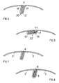
- the end strip 2 is provided with a bevel 12 in order to produce a butt connection, this by bending the strip 2 by approximately 90 ° and through Execution of two further turns in immediate succession (U-shaped).
- the angled end 11, which was also bent through 90 ° in 18 of the strip 3, is introduced into this crank.
- the butt joint which is shown schematically in FIG. 4, is aligned in the radial direction and represents a butt joint with a large space requirement inside the pressure plate.
- a corresponding groove with a suitable depth must therefore be provided in the pressure cylinder. If the depth of this groove is to be reduced, it is advantageous to use the embodiment according to FIG. 5, for the description of which the same reference numerals have been used.
- the bending angle 17 of the crank 12 is less than 90 ° (with reference to the flat starting surface).
- the bending angle 18 of the end piece 11 is also less than 90 ° and essentially equal to the angle 17 of the crank 12. In this way the connection is inclined with respect to the radial direction of the pressure cylinder and the corresponding groove for the insertion of the connection point is in depth ( radial) smaller.
- FIG. 6 shows a further embodiment in which the connection point is completely towards the inner surface of the pressure plate is folded.
- the bend 17 of the angle is approximately 90 °.
- a further bend 19 by 90 ° is provided, and the bend 18 takes place over an angle of 180. In this way, the butt joint 20 is made flat and requires little space on the inside of the pressure plate.
- the butt joints which are shown schematically in FIGS. 4-6, are closed by at least one seam made of hardening filler material or adhesive along the groove between two adjacent folds 17, 18 of the edges 2, 3. This creates a butt joint for the pressure plate, which ensures continuity on the outer circumference of the pressure plate. Irregularities when using the pressure plate, unwanted wear of the pressure plate and other troublesome side effects are avoided.
- a filler seam 8 i.e. a connection in the circumferential direction by means of self-hardening material or by means of an adhesive for producing a smooth and continuous peripheral surface of the plate, can be used for all the butt joints described.
- the pressure plate is not permanently deformed as a cylinder.
- the connecting seam made of adhesive or filler 8 can be destroyed or generally removed.
- an adhesive or a hardening filling material 9 can also be provided inside the crank.
- a connection is thus obtained in the axial direction, which is not a detachable mechanical connection, but instead leads to the establishment of a permanent connection between the cranked plate ends.
- This type of connection which can also be used in other embodiments, leads to the formation of a permanently cylindrical pressure plate.
- the proposed objects are achieved by the invention.
- the butt joint allows the entire usable area of the printing cylinder to be used for recording the print image in practice.
- the plate and the associated butt joint are simple and cheap, the connection can be detached if desired so that the plate again takes the form of a flat plate.
- a limited space requirement for the butt joint in the interior of the plate can be achieved, space that can be created in a simple manner by providing a groove or a recess in the surface of the pressure cylinder.
Landscapes
- Engineering & Computer Science (AREA)
- Mechanical Engineering (AREA)
- Printing Plates And Materials Therefor (AREA)
- Supply, Installation And Extraction Of Printed Sheets Or Plates (AREA)
- Manufacture Or Reproduction Of Printing Formes (AREA)
- Laminated Bodies (AREA)
- Lining Or Joining Of Plastics Or The Like (AREA)
- Replacement Of Web Rolls (AREA)
- Discharging, Photosensitive Material Shape In Electrophotography (AREA)
Claims (4)
- Plaque à imprimer (1) pour l'impression rotative, constituée d'un matériau de support métallique (4) et d'une couche photosensible (5) appliquée sur celui-ci pour la réception d'une image d'impression, la couche photosensible (5) étant enlevée aux deux extrémités opposées (14) de la plaque à imprimer (1) et les deux extrémités coudées (14) de la plaque à imprimer sont reçues par une rainure dans le cylindre d'impression, caractérisée en ce qu il est prévu à une extrémité de plaque (3) un coude (11) de forme angulaire qui peut être inséré dans un coude (12) réalisé en forme de U prévu à l' autre extrémité de plaque (2), et que le joint (20) ainsi obtenu, faisant saillie vers l'intérieur, est fermé par une matière de remplissage (9) pour former une surface de pour tour continue.
- Plaque à imprimer pour l'impression rotative selon la revendication 1, caractérisée en ce que le coude (11,12) s'étend radialement depuis le pourtour de la plaque à imprimer (2,3) vers l'intérieur.
- Plaque à imprimer selon la revendication 1, caractérisée en ce que le coude (11,12) est disposé de façon inclinée par rapport au rayon de plaque.
- Plaque à imprimer selon la revendication 1, caractérisée en ce que le coude (11,12) s'étend tangentiellement au pourtour de plaque (2,3).
Priority Applications (1)
| Application Number | Priority Date | Filing Date | Title |
|---|---|---|---|
| AT88114808T ATE91972T1 (de) | 1987-09-11 | 1988-09-09 | Druckplatte fuer den rotationsdruck. |
Applications Claiming Priority (2)
| Application Number | Priority Date | Filing Date | Title |
|---|---|---|---|
| IT2189887 | 1987-09-11 | ||
| IT8721898A IT1231223B (it) | 1987-09-11 | 1987-09-11 | Metodo per giuntare le estremita' di una lastra per la stampa rotativa e giunzione cosi' ottenuta |
Publications (3)
| Publication Number | Publication Date |
|---|---|
| EP0306986A2 EP0306986A2 (fr) | 1989-03-15 |
| EP0306986A3 EP0306986A3 (en) | 1989-11-15 |
| EP0306986B1 true EP0306986B1 (fr) | 1993-07-28 |
Family
ID=11188415
Family Applications (1)
| Application Number | Title | Priority Date | Filing Date |
|---|---|---|---|
| EP88114808A Expired - Lifetime EP0306986B1 (fr) | 1987-09-11 | 1988-09-09 | Plaque à imprimer pour l'impression rotative |
Country Status (5)
| Country | Link |
|---|---|
| US (1) | US4964338A (fr) |
| EP (1) | EP0306986B1 (fr) |
| AT (1) | ATE91972T1 (fr) |
| DE (1) | DE3882625D1 (fr) |
| IT (1) | IT1231223B (fr) |
Families Citing this family (19)
| Publication number | Priority date | Publication date | Assignee | Title |
|---|---|---|---|---|
| IT1231223B (it) * | 1987-09-11 | 1991-11-26 | Cerutti Spa Off Mec | Metodo per giuntare le estremita' di una lastra per la stampa rotativa e giunzione cosi' ottenuta |
| DE4102858A1 (de) * | 1990-03-08 | 1991-09-12 | Heidelberger Druckmasch Ag | Druckwerkszylinder fuer rotationsdruckmaschinen |
| DE4140768C2 (de) * | 1991-12-11 | 1994-08-18 | Roland Man Druckmasch | Offset-Druckform |
| US5267550A (en) * | 1992-06-04 | 1993-12-07 | Jang Sun Sing | Assembly structure for an external body of a kitchen soot extractor |
| DE4315996C1 (de) * | 1993-05-13 | 1994-08-04 | Roland Man Druckmasch | Registereinrichtung für eine hülsenförmige Offset-Druckform |
| DE4404758C2 (de) * | 1994-02-15 | 1996-06-27 | Roland Man Druckmasch | Verfahren und Vorrichtung zum Wechseln der Bespannung eines Zylinders einer Rollenrotationsdruckmaschine |
| US6779449B1 (en) * | 1994-09-15 | 2004-08-24 | Man Roland Druckmaschinen Ag | Carrying sleeve for printing and transfer forms and a process for production of such a carrying sleeve |
| US5687647A (en) * | 1996-04-26 | 1997-11-18 | Heidelberger Druckmaschinen Ag | Plate cylinder with fixed tensioning plate mounting device |
| FR2763888B1 (fr) * | 1997-05-28 | 1999-07-16 | Rollin Sa | Manchon perfectionne pour cylindre de machine d'impression ou analogue et procede de mise en place de ce manchon |
| US7412924B2 (en) * | 2002-12-16 | 2008-08-19 | Koenig & Bauer Aktiengesellschaft | Printing blanket assembly for a blanket cylinder including filler material at blanket ends |
| JP4298702B2 (ja) * | 2002-12-16 | 2009-07-22 | ケーニッヒ ウント バウエル アクチエンゲゼルシャフト | 印刷機における印刷ブランケットシリンダのための印刷ブランケット装置および印刷ブランケット装置の製造方法 |
| JP3878622B2 (ja) * | 2004-05-19 | 2007-02-07 | 株式会社東京機械製作所 | ブランケット胴の埋め部材 |
| JP4684685B2 (ja) * | 2005-03-03 | 2011-05-18 | 富士フイルム株式会社 | 感光性平版印刷版及びその製造方法 |
| US20060287112A1 (en) * | 2005-06-15 | 2006-12-21 | Mallory Chester L | Gaming machine with a coin collector |
| JP2009285861A (ja) * | 2008-05-27 | 2009-12-10 | Masayuki Izume | 印刷機用版および印刷機 |
| KR20120130517A (ko) * | 2011-05-23 | 2012-12-03 | 삼성디스플레이 주식회사 | 러빙 장치 |
| DE102011084205B4 (de) | 2011-10-10 | 2022-12-08 | Koenig & Bauer Ag | Verfahren zur Herstellung einer Drucktucheinheit |
| JP5942325B2 (ja) * | 2012-09-14 | 2016-06-29 | 富士フイルム株式会社 | 円筒状印刷原版及びその製造方法、並びに、円筒状印刷版及びその製版方法 |
| DE102019111749B4 (de) | 2019-05-07 | 2025-06-12 | Te Connectivity Germany Gmbh | Elektrische Steckverbindung sowie elektrische Entität |
Family Cites Families (13)
| Publication number | Priority date | Publication date | Assignee | Title |
|---|---|---|---|---|
| US3125056A (en) * | 1964-03-17 | kaiser | ||
| GB367436A (en) * | 1930-11-20 | 1932-02-22 | Leslie Thomas Albert Robinson | Improvements in or relating to printing cylinders |
| US2322845A (en) * | 1940-07-03 | 1943-06-29 | Continental Can Co | Method of making black iron sheet metal containers |
| US2685129A (en) * | 1949-11-19 | 1954-08-03 | Jr Robert R Myers | Method for making arcuate printing plates |
| US4332197A (en) * | 1980-05-22 | 1982-06-01 | Beach Manufacturing Corp. | Self-tensioning printing cylinder lock |
| DE3221206A1 (de) * | 1982-06-04 | 1983-12-08 | Basf Ag, 6700 Ludwigshafen | Tiefdruckplatte zum aufspannen auf einen tiefdruck-spannzylinder und verfahren zu ihrer herstellung |
| DK159251C (da) * | 1983-03-12 | 1991-02-18 | Basf Ag | Fremgangsmaade til lukning af spalten mellem en paa et dybtrykapparats trykformcylinder opspaendt dybtrykplades ender, samt indretning ved dybtryksapparatet, til udoevelse af fremgangsmaaden |
| IT1184342B (it) * | 1985-02-27 | 1987-10-28 | G Cerruti Spa Off Mec | Procedimento per il bloccaggio di una lastra da stampa su un cilindro da stampa,dispositivo di bloccaggio nonche' relativa lastra |
| EP0199520A3 (fr) * | 1985-04-19 | 1989-02-08 | Vickers Plc | Presse d'impression en creux et sa méthode de fabrication |
| US4727806A (en) * | 1985-08-26 | 1988-03-01 | Wilson Engraving Company, Inc. | Pin register system for flexographic printing plates |
| DE3600774C1 (de) * | 1986-01-14 | 1987-05-07 | Du Pont Deutschland | Verfahren zum Verkleben von photopolymerisierbaren Druckplatten oder Druckformen fuer den Flexodruck |
| IT1231223B (it) * | 1987-09-11 | 1991-11-26 | Cerutti Spa Off Mec | Metodo per giuntare le estremita' di una lastra per la stampa rotativa e giunzione cosi' ottenuta |
| JP3419896B2 (ja) * | 1994-07-20 | 2003-06-23 | ソニー株式会社 | ディスク装置 |
-
1987
- 1987-09-11 IT IT8721898A patent/IT1231223B/it active
-
1988
- 1988-09-09 AT AT88114808T patent/ATE91972T1/de not_active IP Right Cessation
- 1988-09-09 EP EP88114808A patent/EP0306986B1/fr not_active Expired - Lifetime
- 1988-09-09 DE DE8888114808T patent/DE3882625D1/de not_active Expired - Fee Related
-
1989
- 1989-01-25 US US07/301,654 patent/US4964338A/en not_active Expired - Fee Related
Also Published As
| Publication number | Publication date |
|---|---|
| IT1231223B (it) | 1991-11-26 |
| EP0306986A3 (en) | 1989-11-15 |
| DE3882625D1 (de) | 1993-09-02 |
| US4964338A (en) | 1990-10-23 |
| ATE91972T1 (de) | 1993-08-15 |
| EP0306986A2 (fr) | 1989-03-15 |
| IT8721898A0 (it) | 1987-09-11 |
Similar Documents
| Publication | Publication Date | Title |
|---|---|---|
| EP0306986B1 (fr) | Plaque à imprimer pour l'impression rotative | |
| DE2925058C2 (de) | Drehfeste Preßfüge-Verbindung zweier Bauteile zur Übertragung von Drehmomenten | |
| EP1005401B1 (fr) | Procede pour assembler deux elements de maniere detachable et systemes d'assemblage pour mettre ledit procede en oeuvre | |
| DE19803229B4 (de) | Druckbild-Positionierung | |
| DE1540154B2 (de) | In dem loch einer platte aus hartem, sproedem und nur schwach elastischem werkstoff befestigter elektrischer anschlusstift | |
| DE2857614C2 (de) | Formzylinder fuer Rotationstiofdruckmaschinen | |
| DE3326215A1 (de) | Zylinder fuer eine rotationsdruckmaschine | |
| DE69617614T2 (de) | Ein werkzeug zur herstellung von verbindungsstellen zwischen plattenförmigen teilen | |
| DE3221066A1 (de) | Verfahren und einrichtung zum passgenauen aufziehen von flexiblen klischees auf druckwalzen | |
| EP1289712A1 (fr) | Procede de rectification et rectifieuse | |
| DD295123A5 (de) | Verfahren und vorrichtung zum befestigen von druckplatten auf dem plattenzylinder einer stichtiefdruckmaschine | |
| DE2042937A1 (de) | Verpackungsbehälter | |
| DE19840780A1 (de) | Verfahren und Vorrichtung zum Verbinden von plattenförmigen Bauteilen | |
| EP1572461B1 (fr) | Ensemble blanchet pour cylindre a blanchet et son procede de production | |
| DE2511302C3 (de) | Verfahren zur Herstellung eines Wellendichtringes | |
| DE2820090C2 (fr) | ||
| CH677006A5 (fr) | ||
| DE431764C (de) | Vorrichtung zum Befestigen biegsamer Tiefdruckplatten bei Rotationsdruckmaschinen | |
| DE2626781A1 (de) | Waschmaschine, verfahren zu deren herstellung und vorrichtung zur durchfuehrung des verfahrens | |
| DE3302532C2 (fr) | ||
| EP1578608B1 (fr) | Ensemble blanchet et son procede de production | |
| EP0170956A2 (fr) | Procédé pour fixer des clichés flexibles sur le cylindre de forme d'une machine à imprimer | |
| DE1536975B1 (de) | Einrichtung zum Befestigen von Druckplatten am Plattenzylinder von Rotationsdruckmaschinen,insbesondere Tiefdruckmaschinen | |
| DE2141299C3 (de) | Tietdruckformzylinder | |
| EP4039992B1 (fr) | Pièce de liaison et procédé de fabrication d'une pièce de liaison |
Legal Events
| Date | Code | Title | Description |
|---|---|---|---|
| PUAI | Public reference made under article 153(3) epc to a published international application that has entered the european phase |
Free format text: ORIGINAL CODE: 0009012 |
|
| AK | Designated contracting states |
Kind code of ref document: A2 Designated state(s): AT BE CH DE ES FR GB GR IT LI LU NL SE |
|
| PUAL | Search report despatched |
Free format text: ORIGINAL CODE: 0009013 |
|
| AK | Designated contracting states |
Kind code of ref document: A3 Designated state(s): AT BE CH DE ES FR GB GR IT LI LU NL SE |
|
| 17P | Request for examination filed |
Effective date: 19900418 |
|
| 17Q | First examination report despatched |
Effective date: 19920117 |
|
| GRAA | (expected) grant |
Free format text: ORIGINAL CODE: 0009210 |
|
| ITF | It: translation for a ep patent filed | ||
| AK | Designated contracting states |
Kind code of ref document: B1 Designated state(s): AT BE CH DE ES FR GB GR IT LI LU NL SE |
|
| PG25 | Lapsed in a contracting state [announced via postgrant information from national office to epo] |
Ref country code: SE Effective date: 19930728 Ref country code: NL Effective date: 19930728 Ref country code: GR Free format text: LAPSE BECAUSE OF FAILURE TO SUBMIT A TRANSLATION OF THE DESCRIPTION OR TO PAY THE FEE WITHIN THE PRESCRIBED TIME-LIMIT Effective date: 19930728 Ref country code: FR Effective date: 19930728 Ref country code: ES Free format text: THE PATENT HAS BEEN ANNULLED BY A DECISION OF A NATIONAL AUTHORITY Effective date: 19930728 Ref country code: BE Effective date: 19930728 |
|
| REF | Corresponds to: |
Ref document number: 91972 Country of ref document: AT Date of ref document: 19930815 Kind code of ref document: T |
|
| GBT | Gb: translation of ep patent filed (gb section 77(6)(a)/1977) |
Effective date: 19930727 |
|
| REF | Corresponds to: |
Ref document number: 3882625 Country of ref document: DE Date of ref document: 19930902 |
|
| PG25 | Lapsed in a contracting state [announced via postgrant information from national office to epo] |
Ref country code: AT Effective date: 19930909 |
|
| PG25 | Lapsed in a contracting state [announced via postgrant information from national office to epo] |
Ref country code: LU Free format text: LAPSE BECAUSE OF NON-PAYMENT OF DUE FEES Effective date: 19930930 Ref country code: LI Effective date: 19930930 Ref country code: CH Effective date: 19930930 |
|
| PG25 | Lapsed in a contracting state [announced via postgrant information from national office to epo] |
Ref country code: GB Effective date: 19931028 |
|
| EN | Fr: translation not filed | ||
| NLV1 | Nl: lapsed or annulled due to failure to fulfill the requirements of art. 29p and 29m of the patents act | ||
| REG | Reference to a national code |
Ref country code: CH Ref legal event code: PL |
|
| PLBE | No opposition filed within time limit |
Free format text: ORIGINAL CODE: 0009261 |
|
| STAA | Information on the status of an ep patent application or granted ep patent |
Free format text: STATUS: NO OPPOSITION FILED WITHIN TIME LIMIT |
|
| GBPC | Gb: european patent ceased through non-payment of renewal fee |
Effective date: 19931028 |
|
| PG25 | Lapsed in a contracting state [announced via postgrant information from national office to epo] |
Ref country code: DE Effective date: 19940701 |
|
| 26N | No opposition filed | ||
| PG25 | Lapsed in a contracting state [announced via postgrant information from national office to epo] |
Ref country code: IT Free format text: LAPSE BECAUSE OF NON-PAYMENT OF DUE FEES Effective date: 20050909 |