EP0170956A2 - Procédé pour fixer des clichés flexibles sur le cylindre de forme d'une machine à imprimer - Google Patents
Procédé pour fixer des clichés flexibles sur le cylindre de forme d'une machine à imprimer Download PDFInfo
- Publication number
- EP0170956A2 EP0170956A2 EP85109052A EP85109052A EP0170956A2 EP 0170956 A2 EP0170956 A2 EP 0170956A2 EP 85109052 A EP85109052 A EP 85109052A EP 85109052 A EP85109052 A EP 85109052A EP 0170956 A2 EP0170956 A2 EP 0170956A2
- Authority
- EP
- European Patent Office
- Prior art keywords
- cylinder
- base
- plates
- circumferential direction
- forme cylinder
- Prior art date
- Legal status (The legal status is an assumption and is not a legal conclusion. Google has not performed a legal analysis and makes no representation as to the accuracy of the status listed.)
- Withdrawn
Links
Images

Classifications
-
- B—PERFORMING OPERATIONS; TRANSPORTING
- B41—PRINTING; LINING MACHINES; TYPEWRITERS; STAMPS
- B41F—PRINTING MACHINES OR PRESSES
- B41F27/00—Devices for attaching printing elements or formes to supports
- B41F27/12—Devices for attaching printing elements or formes to supports for attaching flexible printing formes
- B41F27/1262—Devices for attaching printing elements or formes to supports for attaching flexible printing formes without tensioning means
- B41F27/1275—Devices for attaching printing elements or formes to supports for attaching flexible printing formes without tensioning means by means of adhesives, staples
-
- B—PERFORMING OPERATIONS; TRANSPORTING
- B41—PRINTING; LINING MACHINES; TYPEWRITERS; STAMPS
- B41N—PRINTING PLATES OR FOILS; MATERIALS FOR SURFACES USED IN PRINTING MACHINES FOR PRINTING, INKING, DAMPING, OR THE LIKE; PREPARING SUCH SURFACES FOR USE AND CONSERVING THEM
- B41N6/00—Mounting boards; Sleeves Make-ready devices, e.g. underlays, overlays; Attaching by chemical means, e.g. vulcanising
- B41N6/02—Chemical means for fastening printing formes on mounting boards
Definitions
- the present invention relates to a method for clamping flexible printing plates on the forme cylinder of a printing press and a forme cylinder produced by this method with clamped printing plates.
- the forme cylinder with built-in clamping mechanism for the printing plates is complex in construction and therefore also correspondingly expensive.
- the pressure plates themselves, which have to be manufactured very precisely so that the required tightness at the butt edges can be achieved, are also relatively expensive.
- printing plates are also known which consist entirely or at least predominantly of plastic. These plastic plates are only used for a single print job however inexpensive to manufacture. To date, however, no satisfactory solution has been found for clamping such printing plates.
- the present invention has for its object to provide a method of the type mentioned, which allows easy clamping of flexible printing plates, especially those made of plastic.
- the base which is releasably supported on the forme cylinder, and the pressure plates, which are preferably firmly connected to it by gluing, form an annular, practically rigid unit which is stuck on the forme cylinder without the need for an expensive clamping mechanism.
- the printing plates, including the base can be detached from the forme cylinder in a simple manner by cutting along a butt joint of the printing plates. Since there is no adhesive layer between the base and the forme cylinder, a new base can be applied to the forme cylinder after detaching a printing plate together with the base, without the time-consuming machining of the cylinder surface being necessary beforehand.
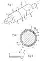
- FIG. 1 shows a perspective view of a printing cylinder 1 which has a forme cylinder 2 on which printing plates 3, 3 ', 3''are clamped, which form three plate tracks 4, 4', 4 '' arranged next to one another.
- the pressure plates 3, 3 ', 3''are as shown in the sectional figure 2, arranged on a base 6, which rests removably on the forme cylinder 2.
- the pressure plates 3, 3 ', 3''are glued to the base 6.
- an adhesive layer is indicated on the outside of the base 6 and designated 7.
- the base 6 is (F ig. 5) by one or more, in the direction of the axis 2a of the plate cylinder 2 arranged side by side carrier webs 8, 9, 10, 11, 12 are formed.
- the length of these carrier webs 8-12 corresponds essentially to the circumferential length of the forme cylinder 2. This means that the ends 8a, 8b (FIG. 2) of the carrier webs 8-12 lie adjacent to one another and define a butt joint or butt joint 13 which extends in the axial direction of the Forme cylinder 2 runs.
- the width of the carrier webs 8-12 can be the same as the width of the printing plates 3, 3 ', 3''. However, it is also possible to make the carrier webs less wide than the printing plates, as is shown in the upper half of FIG.
- FIG. 5 which shows in section a printing cylinder 1 with two plate webs 4, 4 'lying next to one another.
- the carrier webs 9 and 10 or 11 and 12 are half as wide as the overlying printing plates 3, 3 '.
- the carrier web can also be twice as wide as the printing plates 3, 3 '. In the exemplary embodiment according to FIG. 5, this means that the carrier web 8 is essentially the same width as the forme cylinder 2.
- FIGS. 1, 2 and 5 there is only one per plate web 4, 4 ', 4'' Pressure plate 3, 3 'or 3 "is present, which also extends practically over the entire circumferential length of the forme cylinder 2.
- the ends 3a and 3b of the pressure plates 3, 3', 3"' are close together and form a butt joint or butt joint 14, which also extends in the direction of the axis 2a of the forme cylinder 2.
- the butt joint of the pressure plates 3, 3 ', 3'' is now opposite the butt joint 13 of the carrier webs 8 - 12 offset in the circumferential direction of the forme cylinder 2.
- the butt joints 13 and 14 lie diametrically opposite one another. This staggering of the butt joints 13, 14 prevents the pressure plates 3, 3 ', 3''from moving during operation. or can remove the pad 6.
- the base 6 or the carrier webs 8-12 preferably consist of a suitable plastic material.
- the pressure plates 3, 3A, 3 ', 3' ' which must be flexible, have a thin metallic carrier 16, to which a plastic layer 17 is applied (FIG. 3).
- a plastic layer 17 is applied (FIG. 3).
- printing plates 3 made of plastic which have a different structure.
- the butt joints 14 and 15 of the pressure plates 3, 3A, 3 ', 3' ' are filled with a suitable material, preferably a plastic material.
- a suitable material preferably a plastic material.
- the base 6 (or the carrier webs 8 - 12) is placed in the circumferential direction on the forme cylinder 2 and held there detachably but snugly.
- This application of the support 6 takes place with the forme cylinder 2 rotating in the direction of arrow A.
- the adhesive layer 7 Before the application of the support 6, it has already been provided with the adhesive layer 7 on its outside.
- the printing plate 3 is now mounted on the support 6 resting on the forme cylinder 2 in a second operation.
- a conveyor device which is represented by a pair of conveyor rollers 19
- the pressure plate 6 is moved against the forme cylinder 2 rotating in the direction of arrow A and passed between the latter and a pressure roller 20 which rotates in the direction of arrow B.
- this pressure roller 20 By means of this pressure roller 20, the pressure plate 3 is pressed in the direction of arrow C against the forme cylinder 2 and against the base 6, as a result of which the pressure plate 3 is properly bonded to the base 6.
- the pressure plate 3 is applied to the forme cylinder 2 in such a way that the leading end 3a of the pressure plate 3 runs onto the base 6 at a point which is offset in relation to the abutment 13 of this base 6 in the circumferential direction of the forme cylinder 2.
- the joint between the ends 3a and 3b of the pressure plate 3 is, as already described, filled with a plastic filling compound fills.
- the base 6 and the pressure plates 3, 3A, 3 ', 3' 'firmly connected to it form an essentially rigid ring which maintains its ring shape during the printing process, i.e. that doesn't deform.
- the pressure plates 3, 3A, 3 ', 3' ' cannot expand because of the firm adhesive connection to the base 6, since the tensile base 6 does not allow such expansion.
- the pressure plates 3, 3A, 3 ', 3' 'including the base 6 can be detached in a simple manner by cutting along the butt joints 14, 15, 18, 18'. After the printing plates 3, 3A, 3 ', 3' 'and the support 6 have been detached, a new support 6 can be applied to the surface of the forme cylinder 2 without prior extensive cleaning of this surface, since there is no adhesive connection between the support 6 and the forme cylinder 2 must be, which would result in contamination of the cylinder surface.
- the adhesive layer 7 can be formed, for example, by an adhesive film applied to the base 6, the adhesive properties of which are then applied by applying pressure and Heat activated.
- the carrier 17 of the pressure plates 3, 3A, 3 ', 3' 'carrying the plastic layer 17 can also be made of a suitable material other than metal, e.g. made of a reinforced plastic.
Landscapes
- Engineering & Computer Science (AREA)
- Mechanical Engineering (AREA)
- Chemical & Material Sciences (AREA)
- Chemical Kinetics & Catalysis (AREA)
- General Chemical & Material Sciences (AREA)
- Printing Plates And Materials Therefor (AREA)
- Supply, Installation And Extraction Of Printed Sheets Or Plates (AREA)
Applications Claiming Priority (2)
| Application Number | Priority Date | Filing Date | Title |
|---|---|---|---|
| CH3805/84 | 1984-08-08 | ||
| CH380584A CH666863A5 (de) | 1984-08-08 | 1984-08-08 | Verfahren zum aufspannen mindestens einer biegsamen druckplatte auf den formzylinder einer druckmaschine. |
Publications (2)
| Publication Number | Publication Date |
|---|---|
| EP0170956A2 true EP0170956A2 (fr) | 1986-02-12 |
| EP0170956A3 EP0170956A3 (fr) | 1987-11-19 |
Family
ID=4263824
Family Applications (1)
| Application Number | Title | Priority Date | Filing Date |
|---|---|---|---|
| EP85109052A Withdrawn EP0170956A3 (fr) | 1984-08-08 | 1985-07-19 | Procédé pour fixer des clichés flexibles sur le cylindre de forme d'une machine à imprimer |
Country Status (2)
| Country | Link |
|---|---|
| EP (1) | EP0170956A3 (fr) |
| CH (1) | CH666863A5 (fr) |
Cited By (6)
| Publication number | Priority date | Publication date | Assignee | Title |
|---|---|---|---|---|
| AU577627B2 (en) * | 1984-06-29 | 1988-09-29 | Asahi Chemical Industry (U.K.) Limited | Butt joint of flexographic printing plate |
| EP0286020A2 (fr) * | 1987-04-09 | 1988-10-12 | BASF Aktiengesellschaft | Méthode pour relier les bords façonnés de formes flexographiques photopolymérisées |
| FR2707554A1 (fr) * | 1993-07-15 | 1995-01-20 | Roland Man Druckmasch | Bloc d'impression offset et procédé pour sa fabrication. |
| FR2764842A1 (fr) * | 1997-06-24 | 1998-12-24 | Jean Francille | Dispositif de guidage integre pour manchon ou cylindre d'impression et manchon ou cylindre equipe de ce dispositif |
| EP1224076A1 (fr) * | 1999-10-15 | 2002-07-24 | Rotation Dynamics Corporation | Blanchet a manchon cousu et son procede de fabrication et d'utilisation |
| EP1310362A1 (fr) * | 1999-12-02 | 2003-05-14 | Koenig & Bauer Aktiengesellschaft | Cylindre de blanchet d'une machine d'impression |
Families Citing this family (1)
| Publication number | Priority date | Publication date | Assignee | Title |
|---|---|---|---|---|
| DE10016409B4 (de) * | 1999-12-02 | 2007-03-15 | Koenig & Bauer Ag | Druckeinheit einer Rotationsdruckmaschine |
Citations (4)
| Publication number | Priority date | Publication date | Assignee | Title |
|---|---|---|---|---|
| US3085507A (en) * | 1962-03-22 | 1963-04-16 | Lawrence S Kunetka | Rubber printing plate with built-in curvature |
| FR1488594A (fr) * | 1966-08-02 | 1967-07-13 | Procédé pour monter des clichés sur un cylindre de machine à imprimer, et ensemble en résultant | |
| DE2249195A1 (de) * | 1971-01-22 | 1974-04-18 | Jay Morton | Zusammengesetzte druckplatte zum anbringen auf dem plattenzylinder einer offsetdruckmaschine |
| US4047481A (en) * | 1976-03-01 | 1977-09-13 | Container Graphics Corporation | Apparatus for printing indicia on corrugated board and the like |
-
1984
- 1984-08-08 CH CH380584A patent/CH666863A5/de not_active IP Right Cessation
-
1985
- 1985-07-19 EP EP85109052A patent/EP0170956A3/fr not_active Withdrawn
Patent Citations (4)
| Publication number | Priority date | Publication date | Assignee | Title |
|---|---|---|---|---|
| US3085507A (en) * | 1962-03-22 | 1963-04-16 | Lawrence S Kunetka | Rubber printing plate with built-in curvature |
| FR1488594A (fr) * | 1966-08-02 | 1967-07-13 | Procédé pour monter des clichés sur un cylindre de machine à imprimer, et ensemble en résultant | |
| DE2249195A1 (de) * | 1971-01-22 | 1974-04-18 | Jay Morton | Zusammengesetzte druckplatte zum anbringen auf dem plattenzylinder einer offsetdruckmaschine |
| US4047481A (en) * | 1976-03-01 | 1977-09-13 | Container Graphics Corporation | Apparatus for printing indicia on corrugated board and the like |
Cited By (17)
| Publication number | Priority date | Publication date | Assignee | Title |
|---|---|---|---|---|
| AU577627B2 (en) * | 1984-06-29 | 1988-09-29 | Asahi Chemical Industry (U.K.) Limited | Butt joint of flexographic printing plate |
| EP0286020A2 (fr) * | 1987-04-09 | 1988-10-12 | BASF Aktiengesellschaft | Méthode pour relier les bords façonnés de formes flexographiques photopolymérisées |
| EP0286020A3 (en) * | 1987-04-09 | 1989-04-26 | Basf Aktiengesellschaft | Method of joining the cut-up edges of photopolymerised flexographic formes |
| FR2707554A1 (fr) * | 1993-07-15 | 1995-01-20 | Roland Man Druckmasch | Bloc d'impression offset et procédé pour sa fabrication. |
| FR2764842A1 (fr) * | 1997-06-24 | 1998-12-24 | Jean Francille | Dispositif de guidage integre pour manchon ou cylindre d'impression et manchon ou cylindre equipe de ce dispositif |
| WO1998058803A1 (fr) * | 1997-06-24 | 1998-12-30 | Seites | Dispositif de guidage integre pour manchon ou cylindre d'impression et manchon ou cylindre equipe de ce dispositif |
| US6371023B1 (en) * | 1997-06-24 | 2002-04-16 | Societe Seites | Integrated guiding device for printing ferrule or roller and ferrule or roller equipped therewith |
| EP1224076A4 (fr) * | 1999-10-15 | 2006-07-05 | Mlp U S A Inc | Blanchet a manchon cousu et son procede de fabrication et d'utilisation |
| EP1224076A1 (fr) * | 1999-10-15 | 2002-07-24 | Rotation Dynamics Corporation | Blanchet a manchon cousu et son procede de fabrication et d'utilisation |
| US7287470B2 (en) | 1999-10-15 | 2007-10-30 | Mlp U.S.A., Inc. | Offset lithographic printing press having seamed sleeved printing blanket |
| US7530306B2 (en) | 1999-10-15 | 2009-05-12 | Mlp U.S.A., Inc. | Offset lithographic printing press having seamed sleeved printing blanket |
| EP1310362A1 (fr) * | 1999-12-02 | 2003-05-14 | Koenig & Bauer Aktiengesellschaft | Cylindre de blanchet d'une machine d'impression |
| EP1310363A1 (fr) * | 1999-12-02 | 2003-05-14 | Koenig & Bauer Aktiengesellschaft | Groupe d'impression d'une machine d'impression |
| US6920824B2 (en) | 1999-12-02 | 2005-07-26 | Koenig & Bauer Aktiengesellschaft | Printing group of a rotary printing press |
| US7066090B2 (en) | 1999-12-02 | 2006-06-27 | Koenig & Bauer Aktiengesellschaft | Printing group of a rotary printing press |
| US7246557B2 (en) | 1999-12-02 | 2007-07-24 | Koenig & Bauer Aktiengesellschaft | Printing group of a rotary printing press |
| US7523703B2 (en) | 1999-12-02 | 2009-04-28 | Koenig & Bauer Aktiengesellschaft | Printing group of a rotary printing press |
Also Published As
| Publication number | Publication date |
|---|---|
| EP0170956A3 (fr) | 1987-11-19 |
| CH666863A5 (de) | 1988-08-31 |
Similar Documents
| Publication | Publication Date | Title |
|---|---|---|
| DE4217793C1 (de) | Offset-Gummituch und Verfahren zu dessen Herstellung | |
| EP0554542B1 (fr) | Elément pour impression en offset | |
| EP0819550B1 (fr) | Manchon à base de caoutchouc pour machines rotatives offset | |
| EP1157855B1 (fr) | Manchon à base de caoutchouc, notamment pour machines rotatives offset | |
| DE2857614C2 (de) | Formzylinder fuer Rotationstiofdruckmaschinen | |
| DE4323750C2 (de) | Offset-Druckform und Verfahren zur Herstellung einer solchen Offset-Druckform | |
| EP0270485B1 (fr) | Dispositif pour sérigraphie avec des écrans plats et flexibles | |
| DE69705717T2 (de) | Druckzylinder mit fester vorrichtung zum befestigen von druckplatten | |
| CH693589A5 (de) | Verfahren und Vorrichtung zum Aufbringen einer Druckform auf einen Formzylinder. | |
| DE3539586A1 (de) | Verfahren zum aufbringen eines schutzbelages auf einen druckwerkzylinder mit vorrichtungen zur durchfuehrung des verfahrens | |
| DE3125300A1 (de) | Verfahren zur herstellung des aufzuges eines offset-druckzylinders sowie aufzug fuer einen offset-druckzylinder | |
| DE4320464C2 (de) | Übertragungszylinder für Rotationsdruckmaschinen | |
| EP1093915B1 (fr) | Blanchet d'impression avec des entailles pour repérage et méthode pour aligner le blanchet d'impression. | |
| DE4307320C1 (de) | Druckmaschine für indirekte Druckverfahren und Verfahren zur Herstellung einer mit einer Gummischicht oder einem Gummituch versehenen Hülse oder Platte | |
| EP0170956A2 (fr) | Procédé pour fixer des clichés flexibles sur le cylindre de forme d'une machine à imprimer | |
| DE2844426C2 (de) | Verfahren zur Kantenverbindung von lichthärtbaren, thermoplastischen, elastomeren Druckplatten | |
| DE60217124T2 (de) | Verfahren und vorrichtung zum zusammenfügen von kernen | |
| DE19820357C1 (de) | Verfahren und Vorrichtung zum Bearbeiten einer Schweißnaht an eine Trägerhülse | |
| DE2716305A1 (de) | Siebdruck-rahmen | |
| DE19950643B4 (de) | Gummizylinderhülse, insbesondere für Offset-Rollenrotationsdruckmaschinen | |
| DE2948744C2 (de) | Vorrichtung zum Befestigen von Formatplatten zum formatgenauen Übertragen von Klebstoffaufträgen auf Formatwalzen | |
| DD248546A5 (de) | Verfahren und vorrichtung zur befestigung von druckplatten auf dem plattenzylinder einer rollendruckmaschine fuer den stichtiefdruck | |
| DD295123A5 (de) | Verfahren und vorrichtung zum befestigen von druckplatten auf dem plattenzylinder einer stichtiefdruckmaschine | |
| DE3401501A1 (de) | Vorrichtung zum verschliessen des spaltes zwischen den enden einer auf einen formzylinder aufgespannten tiefdruckplatte | |
| DE3614554A1 (de) | Verfahren zum montieren von klischees auf druckzylindern sowie druckwerk |
Legal Events
| Date | Code | Title | Description |
|---|---|---|---|
| PUAI | Public reference made under article 153(3) epc to a published international application that has entered the european phase |
Free format text: ORIGINAL CODE: 0009012 |
|
| AK | Designated contracting states |
Designated state(s): DE FR GB IT NL SE |
|
| PUAL | Search report despatched |
Free format text: ORIGINAL CODE: 0009013 |
|
| AK | Designated contracting states |
Kind code of ref document: A3 Designated state(s): DE FR GB IT NL SE |
|
| 17P | Request for examination filed |
Effective date: 19880517 |
|
| 17Q | First examination report despatched |
Effective date: 19890824 |
|
| STAA | Information on the status of an ep patent application or granted ep patent |
Free format text: STATUS: THE APPLICATION IS DEEMED TO BE WITHDRAWN |
|
| 18D | Application deemed to be withdrawn |
Effective date: 19900103 |