EP0170956A2 - Process for attaching flexible printing plates to the forme cylinder of a printing machine - Google Patents
Process for attaching flexible printing plates to the forme cylinder of a printing machine Download PDFInfo
- Publication number
- EP0170956A2 EP0170956A2 EP85109052A EP85109052A EP0170956A2 EP 0170956 A2 EP0170956 A2 EP 0170956A2 EP 85109052 A EP85109052 A EP 85109052A EP 85109052 A EP85109052 A EP 85109052A EP 0170956 A2 EP0170956 A2 EP 0170956A2
- Authority
- EP
- European Patent Office
- Prior art keywords
- cylinder
- base
- plates
- circumferential direction
- forme cylinder
- Prior art date
- Legal status (The legal status is an assumption and is not a legal conclusion. Google has not performed a legal analysis and makes no representation as to the accuracy of the status listed.)
- Withdrawn
Links
Images

Classifications
-
- B—PERFORMING OPERATIONS; TRANSPORTING
- B41—PRINTING; LINING MACHINES; TYPEWRITERS; STAMPS
- B41F—PRINTING MACHINES OR PRESSES
- B41F27/00—Devices for attaching printing elements or formes to supports
- B41F27/12—Devices for attaching printing elements or formes to supports for attaching flexible printing formes
- B41F27/1262—Devices for attaching printing elements or formes to supports for attaching flexible printing formes without tensioning means
- B41F27/1275—Devices for attaching printing elements or formes to supports for attaching flexible printing formes without tensioning means by means of adhesives, staples
-
- B—PERFORMING OPERATIONS; TRANSPORTING
- B41—PRINTING; LINING MACHINES; TYPEWRITERS; STAMPS
- B41N—PRINTING PLATES OR FOILS; MATERIALS FOR SURFACES USED IN PRINTING MACHINES FOR PRINTING, INKING, DAMPING, OR THE LIKE; PREPARING SUCH SURFACES FOR USE AND CONSERVING THEM
- B41N6/00—Mounting boards; Sleeves Make-ready devices, e.g. underlays, overlays; Attaching by chemical means, e.g. vulcanising
- B41N6/02—Chemical means for fastening printing formes on mounting boards
Definitions
- the present invention relates to a method for clamping flexible printing plates on the forme cylinder of a printing press and a forme cylinder produced by this method with clamped printing plates.
- the forme cylinder with built-in clamping mechanism for the printing plates is complex in construction and therefore also correspondingly expensive.
- the pressure plates themselves, which have to be manufactured very precisely so that the required tightness at the butt edges can be achieved, are also relatively expensive.
- printing plates are also known which consist entirely or at least predominantly of plastic. These plastic plates are only used for a single print job however inexpensive to manufacture. To date, however, no satisfactory solution has been found for clamping such printing plates.
- the present invention has for its object to provide a method of the type mentioned, which allows easy clamping of flexible printing plates, especially those made of plastic.
- the base which is releasably supported on the forme cylinder, and the pressure plates, which are preferably firmly connected to it by gluing, form an annular, practically rigid unit which is stuck on the forme cylinder without the need for an expensive clamping mechanism.
- the printing plates, including the base can be detached from the forme cylinder in a simple manner by cutting along a butt joint of the printing plates. Since there is no adhesive layer between the base and the forme cylinder, a new base can be applied to the forme cylinder after detaching a printing plate together with the base, without the time-consuming machining of the cylinder surface being necessary beforehand.
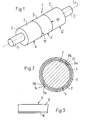
- FIG. 1 shows a perspective view of a printing cylinder 1 which has a forme cylinder 2 on which printing plates 3, 3 ', 3''are clamped, which form three plate tracks 4, 4', 4 '' arranged next to one another.
- the pressure plates 3, 3 ', 3''are as shown in the sectional figure 2, arranged on a base 6, which rests removably on the forme cylinder 2.
- the pressure plates 3, 3 ', 3''are glued to the base 6.
- an adhesive layer is indicated on the outside of the base 6 and designated 7.
- the base 6 is (F ig. 5) by one or more, in the direction of the axis 2a of the plate cylinder 2 arranged side by side carrier webs 8, 9, 10, 11, 12 are formed.
- the length of these carrier webs 8-12 corresponds essentially to the circumferential length of the forme cylinder 2. This means that the ends 8a, 8b (FIG. 2) of the carrier webs 8-12 lie adjacent to one another and define a butt joint or butt joint 13 which extends in the axial direction of the Forme cylinder 2 runs.
- the width of the carrier webs 8-12 can be the same as the width of the printing plates 3, 3 ', 3''. However, it is also possible to make the carrier webs less wide than the printing plates, as is shown in the upper half of FIG.
- FIG. 5 which shows in section a printing cylinder 1 with two plate webs 4, 4 'lying next to one another.
- the carrier webs 9 and 10 or 11 and 12 are half as wide as the overlying printing plates 3, 3 '.
- the carrier web can also be twice as wide as the printing plates 3, 3 '. In the exemplary embodiment according to FIG. 5, this means that the carrier web 8 is essentially the same width as the forme cylinder 2.
- FIGS. 1, 2 and 5 there is only one per plate web 4, 4 ', 4'' Pressure plate 3, 3 'or 3 "is present, which also extends practically over the entire circumferential length of the forme cylinder 2.
- the ends 3a and 3b of the pressure plates 3, 3', 3"' are close together and form a butt joint or butt joint 14, which also extends in the direction of the axis 2a of the forme cylinder 2.
- the butt joint of the pressure plates 3, 3 ', 3'' is now opposite the butt joint 13 of the carrier webs 8 - 12 offset in the circumferential direction of the forme cylinder 2.
- the butt joints 13 and 14 lie diametrically opposite one another. This staggering of the butt joints 13, 14 prevents the pressure plates 3, 3 ', 3''from moving during operation. or can remove the pad 6.
- the base 6 or the carrier webs 8-12 preferably consist of a suitable plastic material.
- the pressure plates 3, 3A, 3 ', 3' ' which must be flexible, have a thin metallic carrier 16, to which a plastic layer 17 is applied (FIG. 3).
- a plastic layer 17 is applied (FIG. 3).
- printing plates 3 made of plastic which have a different structure.
- the butt joints 14 and 15 of the pressure plates 3, 3A, 3 ', 3' ' are filled with a suitable material, preferably a plastic material.
- a suitable material preferably a plastic material.
- the base 6 (or the carrier webs 8 - 12) is placed in the circumferential direction on the forme cylinder 2 and held there detachably but snugly.
- This application of the support 6 takes place with the forme cylinder 2 rotating in the direction of arrow A.
- the adhesive layer 7 Before the application of the support 6, it has already been provided with the adhesive layer 7 on its outside.
- the printing plate 3 is now mounted on the support 6 resting on the forme cylinder 2 in a second operation.
- a conveyor device which is represented by a pair of conveyor rollers 19
- the pressure plate 6 is moved against the forme cylinder 2 rotating in the direction of arrow A and passed between the latter and a pressure roller 20 which rotates in the direction of arrow B.
- this pressure roller 20 By means of this pressure roller 20, the pressure plate 3 is pressed in the direction of arrow C against the forme cylinder 2 and against the base 6, as a result of which the pressure plate 3 is properly bonded to the base 6.
- the pressure plate 3 is applied to the forme cylinder 2 in such a way that the leading end 3a of the pressure plate 3 runs onto the base 6 at a point which is offset in relation to the abutment 13 of this base 6 in the circumferential direction of the forme cylinder 2.
- the joint between the ends 3a and 3b of the pressure plate 3 is, as already described, filled with a plastic filling compound fills.
- the base 6 and the pressure plates 3, 3A, 3 ', 3' 'firmly connected to it form an essentially rigid ring which maintains its ring shape during the printing process, i.e. that doesn't deform.
- the pressure plates 3, 3A, 3 ', 3' ' cannot expand because of the firm adhesive connection to the base 6, since the tensile base 6 does not allow such expansion.
- the pressure plates 3, 3A, 3 ', 3' 'including the base 6 can be detached in a simple manner by cutting along the butt joints 14, 15, 18, 18'. After the printing plates 3, 3A, 3 ', 3' 'and the support 6 have been detached, a new support 6 can be applied to the surface of the forme cylinder 2 without prior extensive cleaning of this surface, since there is no adhesive connection between the support 6 and the forme cylinder 2 must be, which would result in contamination of the cylinder surface.
- the adhesive layer 7 can be formed, for example, by an adhesive film applied to the base 6, the adhesive properties of which are then applied by applying pressure and Heat activated.
- the carrier 17 of the pressure plates 3, 3A, 3 ', 3' 'carrying the plastic layer 17 can also be made of a suitable material other than metal, e.g. made of a reinforced plastic.
Abstract
Description
Die vorliegende Erfindung betrifft ein Verfahren zum Aufspannen von biegsamen Druckplatten auf den Formzylinder einer Druckmaschine sowie ein nach diesem Verfahren hergestellter Formzylinder mit aufgespannten Druckplatten.The present invention relates to a method for clamping flexible printing plates on the forme cylinder of a printing press and a forme cylinder produced by this method with clamped printing plates.
Zum Aufspannen von Druckplatten auf Formzylinder ist es bekannt, im Innern des Formzylinders eine Spannvorrichtung vorzusehen, die an an den Druckplatten angeordneten, in Achsrichtung des Formzylinders verlaufenden Spannleisten angreift (DE-OS 28 04 304 und entsprechende US-PS 4,157,067). Mittels der Spannvorrichtung werden die Druckplatten in Zylinderumfangsrichtung unter Zug gesetzt, was bewirkt, dass die Druckplatten an der Zylinderoberfläche anliegen. Nach Abschluss eines Druckauftrages können die Druckplatten durch Lösen der Spannvorrichtung wieder vom Formzylinder abgenommen und erneut verwendet werden.To clamp printing plates on forme cylinders, it is known to provide a clamping device in the interior of the forme cylinder, which acts on clamping plates arranged on the printing plates and extending in the axial direction of the forme cylinder (DE-OS 28 04 304 and corresponding US Pat. No. 4,157,067). By means of the tensioning device, the pressure plates are placed under tension in the cylinder circumferential direction, which causes the pressure plates to lie against the cylinder surface. After completing a print job, the printing plates can be removed from the forme cylinder again by releasing the clamping device and used again.
Der Formzylinder mit eingebautem Spannmechanismus für die Druckplatten ist aufwendig in der Konstruktion und damit auch entsprechend teuer. Die Druckplatten selbst, welche sehr genau gefertigt werden müssen, damit die erforderliche Dichtheit an den Stosskanten erreicht werden kann, sind ebenfalls verhältnismässig teuer.The forme cylinder with built-in clamping mechanism for the printing plates is complex in construction and therefore also correspondingly expensive. The pressure plates themselves, which have to be manufactured very precisely so that the required tightness at the butt edges can be achieved, are also relatively expensive.
Daneben sind auch Druckplatten bekannt, die ganz oder zumindest zum überwiegenden Teil aus Kunststoff bestehen. Diese Kunststoffplatten werden zwar nur für einen einzigen Druckauftrag verwendet, sind jedoch kostengünstig herstellbar. Doch ist bis heute noch keine zufriedenstellende Lösung zum Aufspannen solcher Druckplatten gefunden worden.In addition, printing plates are also known which consist entirely or at least predominantly of plastic. These plastic plates are only used for a single print job however inexpensive to manufacture. To date, however, no satisfactory solution has been found for clamping such printing plates.
Der vorliegenden Erfindung liegt nun die Aufgabe zugrunde, ein Verfahren der eingangs genannten Art zu schaffen, welches ein einfaches Aufspannen von biegsamen Druckplatten, insbesondere von solchen aus Kunststoff, erlaubt.The present invention has for its object to provide a method of the type mentioned, which allows easy clamping of flexible printing plates, especially those made of plastic.
Diese Aufgabe wird erfindungsgemäss durch die Merkmale des kennzeichnenden Teils des Anspruches 1 gelöst.According to the invention, this object is achieved by the features of the characterizing part of
Die lösbar auf dem Formzylinder aufliegende Unterlage und die mit dieser vorzugsweise durch Klebung fest verbundenen Druckplatten bilden eine ringförmige, praktisch starre Einheit, die auf dem Formzylinder festsitzt, ohne dass ein aufwendiger Spannmechanismus nötig ist. Das Ablösen der Druckplatten samt Unterlage vom Formzylinder kann auf einfache Weise durch Durchtrennen entlang einer Stossfuge der Druckplatten erfolgen. Da zwischen Unterlage und Formzylinder keine Klebstoffschicht vorhanden ist, kann nach Ablösen einer Druckplatte samt Unterlage eine neue Unterlage auf den Formzylinder aufgebracht werden, ohne dass vorgängig eine zeitaufwendige Bearbeitung der Zylinderoberfläche nötig ist.The base, which is releasably supported on the forme cylinder, and the pressure plates, which are preferably firmly connected to it by gluing, form an annular, practically rigid unit which is stuck on the forme cylinder without the need for an expensive clamping mechanism. The printing plates, including the base, can be detached from the forme cylinder in a simple manner by cutting along a butt joint of the printing plates. Since there is no adhesive layer between the base and the forme cylinder, a new base can be applied to the forme cylinder after detaching a printing plate together with the base, without the time-consuming machining of the cylinder surface being necessary beforehand.
Bei einer bevorzugten Weiterausbildung des erfindungsgemässen Verfahrens gemäss Anspruch 2 ist sowohl das Aufbringen der Unterlage wie auch der Druckplatten möglich, ohne das hiefür der Formzylinder aus der Druckmaschine entfernt werden muss. Durch die Versetzung der Stossstellen von Unterlage und Druckplatten in Zylinderumfangsrichtung wird sichergestellt, dass im Betrieb sich weder die Unterlage noch die Druckplatte ablösen können.In a preferred further development of the method according to the invention, it is possible to apply both the base and the printing plates without having to remove the forme cylinder from the printing press. By relocating the joints between the base and the print plates in the circumferential direction of the cylinder ensures that neither the support nor the pressure plate can come off during operation.
Im folgenden wird an Hand der Zeichnung der Erfindungsgegenstand näher erläutert. Es zeigt rein schematisch:
- Fig. 1 perspektivisch ein Druckzylinder mit auf einem Formzylinder aufgespannten Kunststoff-Druckplatten,
- Fig. 2 einen Schnitt durch den Druckzylinder gemäss Fig. 1 in einer rechtwinklig zur Druckzylinderachse stehenden Ebene,
- Fig. 3 einen Teil einer Druckplatte in Seitenansicht,
- Fig. 4 in einer der Fig. 2 entsprechenden Schnittdarstellung eine Variante eines Druckzylinders,
- Fig. 5 einen Längsschnitt durch eine weitere Ausführungsform eines Druckzylinders, und
- Fig. 6 in Seitenansicht einen Formzylinder während des Aufbringens einer Druckplatte auf die Unterlage.
- 1 is a perspective view of a printing cylinder with plastic printing plates clamped on a forme cylinder,
- 2 shows a section through the impression cylinder according to FIG. 1 in a plane perpendicular to the impression cylinder axis,
- 3 shows a part of a printing plate in side view,
- 4 in a sectional view corresponding to FIG. 2 shows a variant of a printing cylinder,
- 5 shows a longitudinal section through a further embodiment of a printing cylinder, and
- Fig. 6 in side view of a forme cylinder during the application of a printing plate to the base.
In Fig. 1 ist in perspektivischer Ansicht ein Druckzylinder 1 gezeigt, der einen Formzylinder 2 aufweist, auf den Druckplatten 3, 3', 3'' aufgespannt sind, die drei nebeneinander angeordnete Plattenbahnen 4, 4', 4'' bilden. Die Druckplatten 3, 3', 3'' sind, wie das die Schnittfigur 2 zeigt, auf einer Unterlage 6 angeordnet, die wegnehmbar auf dem Formzylinder 2 aufliegt. Die Druckplatten 3, 3', 3'' sind mit der Unterlage 6 verklebt. In der Fig. 2 ist auf der Aussenseite der Unterlage 6 eine Klebstoffschicht angedeutet und mit 7 bezeichnet.1 shows a perspective view of a
Die Unterlage 6 wird durch eine oder mehrere, in Richtung der Achse 2a des Formzylinders 2 nebeneinander angeordnete Trägerbahnen 8, 9, 10, 11, 12 (Fig. 5) gebildet. Die Länge dieser Trägerbahnen 8 - 12 entspricht im wesentlichen der Umfangslänge des Formzylinders 2. Das bedeutet, dass die Enden 8a, 8b (Fig. 2) der Trägerbahnen 8 - 12 benachbart zueinander liegen und eine Stossstelle oder Stossfuge 13 festlegen, welche in Achsrichtung des Formzylinders 2 verläuft. Die Breite der Trägerbahnen 8 - 12 kann gleich sein wie die Breite der Druckplatten 3, 3', 3''. Es ist jedoch auch möglich, die Trägerbahnen weniger breit auszubilden, als die Druckplatten, wie das in der oberen Hälfte der Fig. 5 dargestellt ist, welche im Schnitt einen Druckzylinder 1 mit zwei nebeneinanderliegenden Plattenbahnen 4, 4' zeigt. Die Trägerbahnen 9 und 10 bzw. 11 und 12 sind halb so breit wie die darüberliegenden Druckplatten 3, 3'. Wie aus der unteren Hälfte der Fig. 5 hervorgeht, kann die Trägerbahn auch doppelt so breit sein, wie die Druckplatten 3, 3'. Das bedeutet beim Ausführungsbeispiel gemäss Fig. 5, dass die Trägerbahn 8 im wesentlichen gleich breit ist, wie der Formzylinder 2.The
Bei den in den Fig. 1, 2 und 5 gezeigten Ausführungsformen ist pro Plattenbahn 4, 4', 4'' nur eine einzige Druckplatte 3, 3' bzw. 3" vorhanden, welche sich ebenfalls praktisch über die gesamte Umfangslänge des Formzylinders 2 erstreckt. Gleich wie bei den Trägerbahnen 8 - 12 liegen somit die Enden 3a und 3b der Druckplatten 3, 3', 3'' nahe beieinander und bilden zusammen eine Stossstelle oder Stossfuge 14, welche ebenfalls in Richtung der Achse 2a des Formzylinders 2 verläuft. Wie aus Fig. 2 hervorgeht, ist nun die Stossstelle der Druckplatten 3, 3', 3'' gegenüber der Stossstelle 13 der Trägerbahnen 8 - 12 in Umfangsrichtung des Formzylinders 2 versetzt. Beim Ausführungsbeispiel gemäss Fig. 2 liegen sich die Stossfugen 13 und 14 diametral gegenüber. Durch dieses Versetzen der Stossfugen 13, 14 wird verhindert, dass sich im Betrieb die Druckplatten 3, 3', 3'' oder die Unterlage 6 ablösen können.In the embodiments shown in FIGS. 1, 2 and 5, there is only one per
Es ist jedoch auch möglich, pro Plattenbahn 4, 4', 4'' statt nur eine Druckplatte 3, 3', 3'' mehrere Druckplatten 3, 3A vorzusehen, die in Umfangsrichtung des Formzylinders 2 aneinander anschliessen. In Fig. 4 ist eine derartige Ausführungsform gezeigt, bei der pro Plattenbahn 4, 4', 4" zwei Druckplatten 3 und 3A vorgesehen sind. Die beiden Druckplatten 3, 3A schliessen entlang zweier Stossstellen oder Stossfugen 14 und 15 aneinander an, die durch die Plattenenden 3a, 3b der beiden Druckplatten 3, 3A gebildet werden und in Achsrichtung des Formzylinders 2 verlaufen. Wie bereits an Hand der Fig. 2 erläutert, sind diese Stossstellen 14, 15 gegenüber der Stossstelle 13 der Unterlage 6 in Umfangsrichtung des Formzylinders 2 versetzt. Es versteht sich, dass jede Plattenbahn 4, 4', 4" auch aus mehr als zwei Druckplatten 3, 3A gebildet werden kann.However, it is also possible to provide a plurality of
Die Unterlage 6 bzw. die Trägerbahnen 8 - 12 bestehen vorzugsweise aus einem geeigneten Kunststoffmaterial. Zur Erhöhung der Zugfestigkeit in Richtung des Umfanges des Formzylinders 2 kann es erforderlich sein, die Unterlage 6 bzw. die Trägerbahnen 8, 9, 10,11, 12, zu verstärken. Dies kann beispielsweise durch Einbetten von Glas- oder Kohlenstofffasern erfolgen.The
Die Druckplatten 3, 3A, 3', 3'', welche biegsam sein müssen, weisen einen dünnen metallischen Träger 16 auf, auf den eine Kunststoffschicht 17 aufgebracht ist (Fig. 3). Es ist jedoch auch denkbar, Druckplatten 3 aus Kunststoff zu verwenden, die einen anderen Aufbau haben.The
Die Stossfugen 14 und 15 der Druckplatten 3, 3A, 3', 3'' sind mit einem geeigneten Werkstoff, vorzugsweise einem Kunststoffmaterial, ausgegossen. Dasselbe trifft auf die seitlichen Stossfugen 18 und 18' (Fig. 1 und 5) zwischen den Druckplatten 3, 3', 3" benachbarter Plattenbahnen 4, 4', 4" zu.The
Es ist selbstverständlich möglich, auf dem Formzylinder 2 nur eine einzige Plattenbahn 4 vorzusehen, die aus einer oder mehreren Druckplatten 3, 3A gebildet ist. Im weiteren können auch mehr als drei Plattenbahnen 4, 4', 4'' nebeneinander angeordnet werden.It is of course possible to provide only a
Im folgenden wird nun an Hand der Fig. 6 das Aufspannen der Druckplatten 3 auf den Formzylinder 2 erläutert.The clamping of the
In einem ersten Arbeitsgang wird die Unterlage 6 (bzw. die Trägerbahnen 8 - 12) in Umfangsrichtung auf den Formzylinder 2 aufgelegt und auf diesem lösbar, jedoch satt anliegend festgehalten. Dieses Auflegen der Unterlage 6 erfolgt bei sich in Richtung des Pfeiles A drehendem Formzylinder 2. Vor dem Auflegen der Unterlage 6 ist diese auf ihrer Aussenseite bereits mit der Klebstoffschicht 7 versehen worden.In a first operation, the base 6 (or the carrier webs 8 - 12) is placed in the circumferential direction on the
Auf die auf dem Formzylinder 2 aufliegende Unterlage 6 wird nun in einem zweiten Arbeitsgang die Druckplatte 3 aufgezogen. Mittels einer Fördervorrichtung, welche durch ein Förderrollenpaar 19 dargestellt ist, wird die Druckplatte 6 gegen den in Richtung des Pfeiles A drehenden Formzylinder 2 bewegt und zwischen diesem und einer Anpressrolle 20 hindurchgeführt, welche in Richtung des Pfeiles B dreht. Durch diese Anpressrolle 20 wird die Druckplatte 3 in Richtung des Pfeiles C gegen den Formzylinder 2 und an die Unterlage 6 angedrückt, wodurch eine einwandfreie Verklebung der Druckplatte 3 mit der Unterlage 6 erfolgt.The
Das Aufbringen der Druckplatte 3 auf den Formzylinder 2 erfolgt derart, dass das vorlaufende Ende 3a der Druckplatte 3 an einer Stelle auf die Unterlage 6 aufläuft, welche gegenüber der Stossstelle 13 dieser Unterlage 6 in Umfangsrichtung des Formzylinders 2 versetzt ist.The
Nach erfolgtem Aufspannen der Druckplatte 3 auf die Unterlage 6 wird die Stossstelle zwischen den Enden 3a und 3b der Druckplatte 3 wie bereits beschrieben mit einer Füllmasse aus Kunststoff ausgefüllt.After the
Die Unterlage 6 und die mit dieser fest verbundenen Druckplatten 3, 3A, 3', 3'' bilden einen im wesentlichen starren Ring, der während des Druckvorganges seine Ringform beibehält, d.h. der sich nicht deformiert. Die Druckplatten 3, 3A, 3', 3'' können sich wegen der festen Klebeverbindung mit der Unterlage 6 nicht aufweiten, da die zugfeste Unterlage 6 ein solches Aufweiten nicht zulässt.The
Das Ablösen der Druckplatten 3, 3A, 3', 3'' samt Unterlage 6 kann auf einfache Weise durch Durchtrennen entlang der Stossfugen 14, 15, 18, 18' erfolgen. Nach Ablösen der Druckplatten 3, 3A, 3', 3'' und der Unterlage 6 kann auf die Oberfläche des Formzylinders 2 ohne vorherige grosse Reinigung dieser Oberfläche eine neue Unterlage 6 aufgezogen werden, da zwischen der Unterlage 6 und dem Formzylinder 2 keine Klebverbindung vorhanden sein muss, welche eine Verschmutzung der Zylinderoberfläche zur Folge haben würde.The
Im folgenden wird auf einige Varianten hingewiesen:
- Durch Wärmeeinwirkung kann der nach dem
Aufbringen der Druckplatten Unterlage 6 stattfindende Verklebungsprozess beschleunigt werden.
- The bonding process taking place after the
printing plates base 6 can be accelerated by the action of heat.
Im weiteren ist es auch denkbar, die Unterlage 6 erst nach dem Aufbringen auf den Zylinder 2 mit der Klebstoffschicht 7 zu versehen. Die Klebstoffschicht 7 kann beispielsweise durch eine auf die Unterlage 6 aufgebrachte Klebefolie gebildet werden, deren Klebeeigenschaften dann durch Anwendung von Druck und Wärme aktiviert werden.Furthermore, it is also conceivable to provide the
Statt einer Klebverbindung zwischen Unterlage 6 und Druckplatten 3, 3A, 3', 3'' kann auch auf andere geeignete Weise eine feste Verbindung zwischen diesen Teilen hergestellt werden.Instead of an adhesive connection between the
Der die Kunststoffschicht 17 tragende Träger 17 der Druckplatten 3, 3A, 3', 3'' kann auch aus einem anderen geeigneten Werkstoff sein als Metall, so z.B. aus einem verstärkten Kunststoff.The
Das beschriebene Aufspannen von Druckplatten 3, 3A, 3', 3'' eignet sich insbesondere für Tiefdruckzylinder. Doch ist es ebenfalls möglich, auf die beschriebene Weise Druckplatten auf Hochdruck- oder Offsetdruckzylinder aufzuspannen.The described clamping of
Claims (13)
Applications Claiming Priority (2)
| Application Number | Priority Date | Filing Date | Title |
|---|---|---|---|
| CH380584A CH666863A5 (en) | 1984-08-08 | 1984-08-08 | METHOD FOR CLAMPING AT LEAST ONE BENDING PRINT PLATE ON THE FORM CYLINDER OF A PRINTING MACHINE. |
| CH3805/84 | 1984-08-08 |
Publications (2)
| Publication Number | Publication Date |
|---|---|
| EP0170956A2 true EP0170956A2 (en) | 1986-02-12 |
| EP0170956A3 EP0170956A3 (en) | 1987-11-19 |
Family
ID=4263824
Family Applications (1)
| Application Number | Title | Priority Date | Filing Date |
|---|---|---|---|
| EP85109052A Withdrawn EP0170956A3 (en) | 1984-08-08 | 1985-07-19 | Process for attaching flexible printing plates to the forme cylinder of a printing machine |
Country Status (2)
| Country | Link |
|---|---|
| EP (1) | EP0170956A3 (en) |
| CH (1) | CH666863A5 (en) |
Cited By (6)
| Publication number | Priority date | Publication date | Assignee | Title |
|---|---|---|---|---|
| AU577627B2 (en) * | 1984-06-29 | 1988-09-29 | Asahi Chemical Industry (U.K.) Limited | Butt joint of flexographic printing plate |
| EP0286020A2 (en) * | 1987-04-09 | 1988-10-12 | BASF Aktiengesellschaft | Method of joining the cut-up edges of photopolymerised flexographic formes |
| FR2707554A1 (en) * | 1993-07-15 | 1995-01-20 | Roland Man Druckmasch | Offset printing block and process for its manufacture. |
| FR2764842A1 (en) * | 1997-06-24 | 1998-12-24 | Jean Francille | INTEGRATED GUIDANCE DEVICE FOR PRINT SLEEVE OR CYLINDER AND SLEEVE OR CYLINDER EQUIPPED WITH SUCH DEVICE |
| EP1224076A1 (en) * | 1999-10-15 | 2002-07-24 | Rotation Dynamics Corporation | Seamed sleeved blanket and method for making and using same |
| EP1310362A1 (en) * | 1999-12-02 | 2003-05-14 | Koenig & Bauer Aktiengesellschaft | Blanket cylinder of a printing machine |
Families Citing this family (1)
| Publication number | Priority date | Publication date | Assignee | Title |
|---|---|---|---|---|
| DE10016409B4 (en) * | 1999-12-02 | 2007-03-15 | Koenig & Bauer Ag | Printing unit of a rotary printing machine |
Citations (4)
| Publication number | Priority date | Publication date | Assignee | Title |
|---|---|---|---|---|
| US3085507A (en) * | 1962-03-22 | 1963-04-16 | Lawrence S Kunetka | Rubber printing plate with built-in curvature |
| FR1488594A (en) * | 1966-08-02 | 1967-07-13 | Process for mounting clichés on a printing machine cylinder, and resulting assembly | |
| DE2249195A1 (en) * | 1971-01-22 | 1974-04-18 | Jay Morton | COMPOSITE PRINTING PLATE FOR ATTACHING ON THE PLATE CYLINDER OF AN OFFSET PRINTING MACHINE |
| US4047481A (en) * | 1976-03-01 | 1977-09-13 | Container Graphics Corporation | Apparatus for printing indicia on corrugated board and the like |
-
1984
- 1984-08-08 CH CH380584A patent/CH666863A5/en not_active IP Right Cessation
-
1985
- 1985-07-19 EP EP85109052A patent/EP0170956A3/en not_active Withdrawn
Patent Citations (4)
| Publication number | Priority date | Publication date | Assignee | Title |
|---|---|---|---|---|
| US3085507A (en) * | 1962-03-22 | 1963-04-16 | Lawrence S Kunetka | Rubber printing plate with built-in curvature |
| FR1488594A (en) * | 1966-08-02 | 1967-07-13 | Process for mounting clichés on a printing machine cylinder, and resulting assembly | |
| DE2249195A1 (en) * | 1971-01-22 | 1974-04-18 | Jay Morton | COMPOSITE PRINTING PLATE FOR ATTACHING ON THE PLATE CYLINDER OF AN OFFSET PRINTING MACHINE |
| US4047481A (en) * | 1976-03-01 | 1977-09-13 | Container Graphics Corporation | Apparatus for printing indicia on corrugated board and the like |
Cited By (17)
| Publication number | Priority date | Publication date | Assignee | Title |
|---|---|---|---|---|
| AU577627B2 (en) * | 1984-06-29 | 1988-09-29 | Asahi Chemical Industry (U.K.) Limited | Butt joint of flexographic printing plate |
| EP0286020A2 (en) * | 1987-04-09 | 1988-10-12 | BASF Aktiengesellschaft | Method of joining the cut-up edges of photopolymerised flexographic formes |
| EP0286020A3 (en) * | 1987-04-09 | 1989-04-26 | Basf Aktiengesellschaft | Method of joining the cut-up edges of photopolymerised flexographic formes |
| FR2707554A1 (en) * | 1993-07-15 | 1995-01-20 | Roland Man Druckmasch | Offset printing block and process for its manufacture. |
| FR2764842A1 (en) * | 1997-06-24 | 1998-12-24 | Jean Francille | INTEGRATED GUIDANCE DEVICE FOR PRINT SLEEVE OR CYLINDER AND SLEEVE OR CYLINDER EQUIPPED WITH SUCH DEVICE |
| WO1998058803A1 (en) * | 1997-06-24 | 1998-12-30 | Seites | Integrated guiding device for printing ferrule or roller and ferrule or roller equipped therewith |
| US6371023B1 (en) * | 1997-06-24 | 2002-04-16 | Societe Seites | Integrated guiding device for printing ferrule or roller and ferrule or roller equipped therewith |
| EP1224076A4 (en) * | 1999-10-15 | 2006-07-05 | Mlp U S A Inc | Seamed sleeved blanket and method for making and using same |
| EP1224076A1 (en) * | 1999-10-15 | 2002-07-24 | Rotation Dynamics Corporation | Seamed sleeved blanket and method for making and using same |
| US7287470B2 (en) | 1999-10-15 | 2007-10-30 | Mlp U.S.A., Inc. | Offset lithographic printing press having seamed sleeved printing blanket |
| US7530306B2 (en) | 1999-10-15 | 2009-05-12 | Mlp U.S.A., Inc. | Offset lithographic printing press having seamed sleeved printing blanket |
| EP1310362A1 (en) * | 1999-12-02 | 2003-05-14 | Koenig & Bauer Aktiengesellschaft | Blanket cylinder of a printing machine |
| EP1310363A1 (en) * | 1999-12-02 | 2003-05-14 | Koenig & Bauer Aktiengesellschaft | Printing unit of a printing machine |
| US6920824B2 (en) | 1999-12-02 | 2005-07-26 | Koenig & Bauer Aktiengesellschaft | Printing group of a rotary printing press |
| US7066090B2 (en) | 1999-12-02 | 2006-06-27 | Koenig & Bauer Aktiengesellschaft | Printing group of a rotary printing press |
| US7246557B2 (en) | 1999-12-02 | 2007-07-24 | Koenig & Bauer Aktiengesellschaft | Printing group of a rotary printing press |
| US7523703B2 (en) | 1999-12-02 | 2009-04-28 | Koenig & Bauer Aktiengesellschaft | Printing group of a rotary printing press |
Also Published As
| Publication number | Publication date |
|---|---|
| EP0170956A3 (en) | 1987-11-19 |
| CH666863A5 (en) | 1988-08-31 |
Similar Documents
| Publication | Publication Date | Title |
|---|---|---|
| DE4217793C1 (en) | Offset blanket and process for its manufacture | |
| EP0554542B1 (en) | Offset printing element | |
| EP0819550B1 (en) | Rubber sleeve for rotary offset printing presses | |
| EP1157855B1 (en) | Rubber sleeve, especially for rotary offset printing presses | |
| DE2857614C2 (en) | Forme cylinders for rotary printing presses | |
| DE4323750C2 (en) | Offset printing form and method for producing such an offset printing form | |
| EP0270485B1 (en) | Apparatus for a screen printing machine with flat, flexible screens | |
| CH693589A5 (en) | Method and apparatus for applying a printing plate on a forme cylinder. | |
| DE3539586A1 (en) | METHOD FOR APPLYING A PROTECTIVE COATING TO A PRINTING CYLINDER WITH DEVICES FOR CARRYING OUT THE METHOD | |
| DE3125300A1 (en) | METHOD FOR PRODUCING THE LIFT OF AN OFFSET PRINTING CYLINDER AND LIFT FOR AN OFFSET PRINTING CYLINDER | |
| DE4320464C2 (en) | Transfer cylinders for rotary printing machines | |
| EP1093915B1 (en) | Printing blanket with notches for registering and method for aligning the printing blanket | |
| DE4307320C1 (en) | Indirect printing-press with blanket cylinder | |
| EP0170956A2 (en) | Process for attaching flexible printing plates to the forme cylinder of a printing machine | |
| DE102007062791A1 (en) | Cylindrical sleeve for printing roller of printing machine, is attached on outer periphery of corpus side of base printing roller provided on printing machine with inner peripheral layer | |
| DE19820357C1 (en) | Method of welding seam in printer cylinder shell | |
| DE60217124T2 (en) | METHOD AND DEVICE FOR COMBINING NUCLEARS | |
| DE2716305A1 (en) | SCREEN PRINTED FRAME | |
| DE19950643B4 (en) | Rubber cylinder sleeve, especially for offset web presses | |
| DE2948744C2 (en) | Device for attaching format plates for exact format transfer of adhesive applications to format rollers | |
| DE4211638C2 (en) | Process and device for painting and for printing sheets in a coating unit with a printing unit | |
| DD248546A5 (en) | METHOD AND DEVICE FOR FIXING PRESSURE PLATES ON THE PLATE CYLINDER OF A ROLL PRINTING MACHINE FOR STITCH PRINTING | |
| DD295123A5 (en) | METHOD AND DEVICE FOR FIXING PRESSURE PLATES ON THE PLATE CYLINDER OF A STITCH PRINTING MACHINE | |
| DE2820090C2 (en) | ||
| DE3401501A1 (en) | DEVICE FOR CLOSING THE GAP BETWEEN THE ENDS OF A PRINTING PLATE CLAMPED ON A FORM CYLINDER |
Legal Events
| Date | Code | Title | Description |
|---|---|---|---|
| PUAI | Public reference made under article 153(3) epc to a published international application that has entered the european phase |
Free format text: ORIGINAL CODE: 0009012 |
|
| AK | Designated contracting states |
Designated state(s): DE FR GB IT NL SE |
|
| PUAL | Search report despatched |
Free format text: ORIGINAL CODE: 0009013 |
|
| AK | Designated contracting states |
Kind code of ref document: A3 Designated state(s): DE FR GB IT NL SE |
|
| 17P | Request for examination filed |
Effective date: 19880517 |
|
| 17Q | First examination report despatched |
Effective date: 19890824 |
|
| STAA | Information on the status of an ep patent application or granted ep patent |
Free format text: STATUS: THE APPLICATION IS DEEMED TO BE WITHDRAWN |
|
| 18D | Application deemed to be withdrawn |
Effective date: 19900103 |