EP0306986B1 - Printing plate for rotary printing - Google Patents
Printing plate for rotary printing Download PDFInfo
- Publication number
- EP0306986B1 EP0306986B1 EP88114808A EP88114808A EP0306986B1 EP 0306986 B1 EP0306986 B1 EP 0306986B1 EP 88114808 A EP88114808 A EP 88114808A EP 88114808 A EP88114808 A EP 88114808A EP 0306986 B1 EP0306986 B1 EP 0306986B1
- Authority
- EP
- European Patent Office
- Prior art keywords
- plate
- printing
- printing plate
- cylinder
- join
- Prior art date
- Legal status (The legal status is an assumption and is not a legal conclusion. Google has not performed a legal analysis and makes no representation as to the accuracy of the status listed.)
- Expired - Lifetime
Links
Images

Classifications
-
- B—PERFORMING OPERATIONS; TRANSPORTING
- B41—PRINTING; LINING MACHINES; TYPEWRITERS; STAMPS
- B41F—PRINTING MACHINES OR PRESSES
- B41F27/00—Devices for attaching printing elements or formes to supports
- B41F27/12—Devices for attaching printing elements or formes to supports for attaching flexible printing formes
- B41F27/1293—Devices for filling up the cylinder gap; Devices for removing the filler
-
- B—PERFORMING OPERATIONS; TRANSPORTING
- B41—PRINTING; LINING MACHINES; TYPEWRITERS; STAMPS
- B41F—PRINTING MACHINES OR PRESSES
- B41F27/00—Devices for attaching printing elements or formes to supports
- B41F27/12—Devices for attaching printing elements or formes to supports for attaching flexible printing formes
- B41F27/1281—Devices for attaching printing elements or formes to supports for attaching flexible printing formes details of the printing plate ends
-
- Y—GENERAL TAGGING OF NEW TECHNOLOGICAL DEVELOPMENTS; GENERAL TAGGING OF CROSS-SECTIONAL TECHNOLOGIES SPANNING OVER SEVERAL SECTIONS OF THE IPC; TECHNICAL SUBJECTS COVERED BY FORMER USPC CROSS-REFERENCE ART COLLECTIONS [XRACs] AND DIGESTS
- Y10—TECHNICAL SUBJECTS COVERED BY FORMER USPC
- Y10T—TECHNICAL SUBJECTS COVERED BY FORMER US CLASSIFICATION
- Y10T29/00—Metal working
- Y10T29/49—Method of mechanical manufacture
- Y10T29/49826—Assembling or joining
- Y10T29/49908—Joining by deforming
- Y10T29/49936—Surface interlocking
Definitions
- the above invention relates to a printing plate for rotary printing.
- a printing plate according to the preamble of claim 1 is already known from document EP-A-0 096 275.
- This known type of plate connection has several disadvantages. On the one hand, a special and, above all, highly precise machining of the two plate ends (punching process) is required in order to enable a positive connection of the ends. Furthermore, the punched-outs for the positive connection necessarily have considerable dimensions, which considerably restrict the usable area for applying the printed image to the plate. Furthermore, the pressure plate described can only be used together with a cylinder to be specially trained. The known plates are not interchangeable and mostly the positive connection is to be made directly on the printing cylinder on which the printing plate is used.
- the object of the above invention is to avoid the disadvantages of the prior art and to create a new one Propose printing plate for rotary printing machines.
- connection joint between the plate ends can be inclined at a certain angle to the radius of the cylinder or can be arranged completely bent.
- connection joint can be made as a permanent connection by filling an adhesive between the bent and joined plate ends.
- the printing plate can also be made detachable in order to be able to return to its original, flat shape after the printing process.
- FIG. 1 shows a printing plate 1 of a known type for use in a rotary printing press.
- the pressure plate 1 is only partially shown and has ends 2 and 3.
- the plate 1 shown has already been deformed in such a way that an elastic body with a cylindrical shape is formed.
- the plate ends 2 and 3 are not yet connected to one another in FIG. 1.
- the length or development of the plate 1 is larger than the circumference of the printing cylinder used, since two opposite edge strips 2 and 3 must be available for the production of the plate joint.
- Fig. 2 shows a partial section of the edge 3, which shows the structure of the printing plate.
- the plate consists of a metallic Carrier layer 4, for example made of sheet steel, on which a photosensitive coating 5 made of polymer material is applied. This coating is then processed photochemically in a known manner in order to create the printed image on the printing plate.
- FIG. 2 shows the right end piece of the plate, which has already been stripped of the photosensitive coating along the strip 14.
- the strip 14 is later used to make the butt joint between the two plate ends.
- the photosensitive layer 5 can be removed by photochemical means or by machining, as shown in FIG. 2.
- FIG. 3 another exemplary embodiment of a printing plate is shown in section.
- the plate consists of a metallic carrier material 4, a photosensitive layer 5 and a thin intermediate layer 6, which has the task of ensuring better anchoring of the photosensitive layer on the carrier material 4.
- a strip 15 was stripped of the photosensitive coating. This can e.g. also take place photochemically, leaving the intermediate strip 6.
- the preparation of the strip 15 can also be done by mechanical material removal. In this case, the intermediate layer 6 would also be removed in an advantageous manner.
- the end strip 2 is provided with a bevel 12 in order to produce a butt connection, this by bending the strip 2 by approximately 90 ° and through Execution of two further turns in immediate succession (U-shaped).
- the angled end 11, which was also bent through 90 ° in 18 of the strip 3, is introduced into this crank.
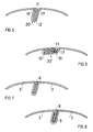
- the butt joint which is shown schematically in FIG. 4, is aligned in the radial direction and represents a butt joint with a large space requirement inside the pressure plate.
- a corresponding groove with a suitable depth must therefore be provided in the pressure cylinder. If the depth of this groove is to be reduced, it is advantageous to use the embodiment according to FIG. 5, for the description of which the same reference numerals have been used.
- the bending angle 17 of the crank 12 is less than 90 ° (with reference to the flat starting surface).
- the bending angle 18 of the end piece 11 is also less than 90 ° and essentially equal to the angle 17 of the crank 12. In this way the connection is inclined with respect to the radial direction of the pressure cylinder and the corresponding groove for the insertion of the connection point is in depth ( radial) smaller.
- FIG. 6 shows a further embodiment in which the connection point is completely towards the inner surface of the pressure plate is folded.
- the bend 17 of the angle is approximately 90 °.
- a further bend 19 by 90 ° is provided, and the bend 18 takes place over an angle of 180. In this way, the butt joint 20 is made flat and requires little space on the inside of the pressure plate.
- the butt joints which are shown schematically in FIGS. 4-6, are closed by at least one seam made of hardening filler material or adhesive along the groove between two adjacent folds 17, 18 of the edges 2, 3. This creates a butt joint for the pressure plate, which ensures continuity on the outer circumference of the pressure plate. Irregularities when using the pressure plate, unwanted wear of the pressure plate and other troublesome side effects are avoided.
- a filler seam 8 i.e. a connection in the circumferential direction by means of self-hardening material or by means of an adhesive for producing a smooth and continuous peripheral surface of the plate, can be used for all the butt joints described.
- the pressure plate is not permanently deformed as a cylinder.
- the connecting seam made of adhesive or filler 8 can be destroyed or generally removed.
- an adhesive or a hardening filling material 9 can also be provided inside the crank.
- a connection is thus obtained in the axial direction, which is not a detachable mechanical connection, but instead leads to the establishment of a permanent connection between the cranked plate ends.
- This type of connection which can also be used in other embodiments, leads to the formation of a permanently cylindrical pressure plate.
- the proposed objects are achieved by the invention.
- the butt joint allows the entire usable area of the printing cylinder to be used for recording the print image in practice.
- the plate and the associated butt joint are simple and cheap, the connection can be detached if desired so that the plate again takes the form of a flat plate.
- a limited space requirement for the butt joint in the interior of the plate can be achieved, space that can be created in a simple manner by providing a groove or a recess in the surface of the pressure cylinder.
Abstract
Description
Die vorstehende Erfindung betrifft eine Druckplatte fuer den Rotationsdruck. Eine Druckplatte gemäß dem Oberbegriff des Anspruchs 1 ist bereits aus dem Dokument EP-A-0 096 275 bekannt. Um die Produktivitaet von Rotationsdruckmaschinen zu erhoehen, wurde bereits vorgeschlagen, die Kupferbeschichtung auf dem Druckzylinder durch eine, die Druckplatte bildende Matritze zu ersetzen, deren Aussenbeschichtung aus fotoempfindlichem Material besteht.The above invention relates to a printing plate for rotary printing. A printing plate according to the preamble of
Da derartige Matritzen ueblicherweise als flache Platten hergestellt werden, besteht die Notwendigkeit, die beiden Enden der Druckplatte zusammenzufuegen, und diese Druckplatte genau und ortsfest auf dem Druckzylinder zu montieren.Since such matrices are usually manufactured as flat plates, there is a need to join the two ends of the pressure plate and to mount this pressure plate precisely and stationary on the pressure cylinder.
Es wurde bereits vorgeschlagen, die beiden Enden der Druckplatte durch einen Stanzvorgang zu bearbeiten, um somit eine formschluessige gegenseitige Verbindung der Plattenenden zu ermoeglichen. Diese Aussstanzungen, die eine formschluessige Verbindung der Plattenenden ermoeglichen, verhindern eine Trennung der Plattenenden in Tangentialrichtung des Zylinders. Bei der bekannten Ausfuehrung ist ein Kleber oder ein aushaertendes Material auf der Plattenoeberflaeche vorgesehen, um zu vermeiden, dass sich die zusammengefuegten Enden der Platte oeffnen. Ferner ist dieses Fuellmaterial vorgesehen, damit an der Stosstelle eine fuer Druckplatten notwendige Kontinuitaet und Glaette der Oberflaeche gewaehrleistet wird. Eine derartige Druckplatte findet Verwendung mit einem in Radialrichtung dehnbaren Zylinder, der magnetische Haltevorrichtungen aufweist, welche die Enden der Druckplatte auf dem Umfang des Druckzylinders festlegt.It has already been proposed to machine the two ends of the printing plate by means of a stamping process, in order to enable a form-fitting mutual connection of the plate ends. These punchings, which enable a form-fitting connection of the plate ends, prevent separation of the plate ends in Tangential direction of the cylinder. In the known embodiment, an adhesive or a hardening material is provided on the surface of the plate in order to prevent the joined ends of the plate from opening. Furthermore, this filling material is provided so that the continuity and smoothness of the surface necessary for printing plates is ensured at the butt joint. Such a printing plate is used with a radially expandable cylinder which has magnetic holding devices which fix the ends of the printing plate on the circumference of the printing cylinder.
Diese bekannte Art der Plattenverbindung hat verschiedene Nachteile. Einmal bedarf es einer besonderen und vor allem hochgenauen Bearbeitung der beiden Plattenenden (Stanzvorgang), um eine formschluessige Verbindung der Enden zu ermoeglichen. Desweiteren weisen die Ausstanzungen fuer die formschluessige Verbindung zwangsweise erhebliche Abmessungen auf, welche die nutzbare Flaeche zur Aufbringung des Druckbildes auf der Platte wesentlich einschraenken. Desweiteren kann die beschriebene Druckplatte nur gemeinsam mit einem besonders auszubildenden Zylinder verwendet werden. Die bekannten Platten sind nicht untereinander austauschbar und meistens ist die formschluessige Verbindung direkt auf dem Druckzylinder herzustellen, auf dem die Druckplatte zum Einsatz kommt.This known type of plate connection has several disadvantages. On the one hand, a special and, above all, highly precise machining of the two plate ends (punching process) is required in order to enable a positive connection of the ends. Furthermore, the punched-outs for the positive connection necessarily have considerable dimensions, which considerably restrict the usable area for applying the printed image to the plate. Furthermore, the pressure plate described can only be used together with a cylinder to be specially trained. The known plates are not interchangeable and mostly the positive connection is to be made directly on the printing cylinder on which the printing plate is used.
Aufgabe der vorstehenden Erfindung ist es, die Nachteile des Standes der Technik zu vermeiden und eine neue Druckplatte fuer Rotationsdruckmaschinen vorzuschlagen.The object of the above invention is to avoid the disadvantages of the prior art and to create a new one Propose printing plate for rotary printing machines.
Diese Aufgabe wird mit den Merkmalen im kennzeichnenden Teil des Anspruchs 1 gelöst.This object is achieved with the features in the characterizing part of
Entsprechend einer weiteren vorteilhaften Ausfuehrungsform kann der Verbindungsstoss zwischen den Plattenenden in einem bestimmten Winkel zum Radius des Zylinders geneigt oder vollkommen umgebogen angeordnet sein.According to a further advantageous embodiment, the connection joint between the plate ends can be inclined at a certain angle to the radius of the cylinder or can be arranged completely bent.
Desweiteren kann der Verbindungsstoss als dauerhafte Verbindung dadurch hergestellt werden, dass ein Kleber zwischen die abgebogenen und zusammengefuegten Plattenenden eingefuellt wird. Die Druckplatte kann auch loesbar hergestellt werden, um ihre urspruengliche, flache Form nach dem Druckvorgang wieder einnehmen zu koennen.Furthermore, the connection joint can be made as a permanent connection by filling an adhesive between the bent and joined plate ends. The printing plate can also be made detachable in order to be able to return to its original, flat shape after the printing process.
Weitere Ausfuehrungsbeispiele der Erfindung koennen den Unteranspruechen entnommen werden.Further exemplary embodiments of the invention can be found in the subclaims.
Die Erfindung kann der nun folgenden Beschreibung einiger Ausfuehrungsbeispiele entnommen werden, die in den folgenden Zeichnungen dargestellt sind.The invention can be found in the following description of some exemplary embodiments, which are shown in the following drawings.
Es zeigen:
- Fig. 1 in perspektiver Ansicht ein Teilstueck der Druckplatte vor dem Zusammenfuegen;
- Fig. 2 und 3 zwei mogliche Ausfuehrungsformen von Druckplatten im Schnitt;
- Fig. 4-6 drei moegliche Ausfuehrungsformen des Plattenstosses; und
- Fig. 7 und 8 weitere moegliche Ausfuehrungsformen des Stosses entsprechend Fig. 5.
- Figure 1 is a perspective view of a portion of the pressure plate before assembly.
- Figures 2 and 3 two possible embodiments of printing plates in section.
- Fig. 4-6 three possible embodiments of the plate joint; and
- 7 and 8 further possible embodiments of the joint corresponding to FIG. 5.
In Fig. 1 ist eine Druckplatte 1 bekannter Bauart fuer den Einsatz in einer Rotationsdruckmaschine dargestellt. Die Druckplatte 1 ist nur teilweise gezeigt und weist Enden 2 und 3 auf. Die dargestellte Platte 1 wurde bereits derartig verformt, dass ein elastischer Koerper mit zylindrischer Form gebildet wird. Die Plattenenden 2 und 3 sind in Fig. 1 noch nicht miteinander verbunden.1 shows a
Gemaess der Erfindung ist die Laenge oder Abwicklung der Platte 1 groesser als der Umfang des verwendeten Druckzylinders, da zwei gegenueberliegende Randstreifen 2 und 3 zur Herstellung des Plattenstosses zur Verfuegung stehen muessen.According to the invention, the length or development of the
Fig. 2 stellt einen Teilschnitt des Randes 3 dar, der den Aufbau der Druckplatte kenntlich macht. Die Platte besteht aus einer metallischen Traegerschicht 4, z.B. aus Stahlblech, auf dem eine fotoempfindliche Beschichtung 5 aus Polymermaterial aufgetragen ist. Diese Beschichtung wird im Anschluss in bekannter Weise fotochemisch bearbeitet um das Druckbild auf der Druckplatte zu erstellen.Fig. 2 shows a partial section of the
Fig. 2 zeigt das rechte Endstueck der Platte, das bereits von der fotoempfindlichen Beschichtung laengs des Streifens 14 befreit wurde. Der Streifen 14 wird spaeter zur Herstellung der Stossverbindung zwischen den zwei Plattenenden verwendet. Das Abtragen der fotoempfindlichen Schicht 5 kann auf fotochemischem Wege oder aber durch spanabhebende Bearbeitung, wie in Fig. 2 dargestellt ist, erfolgen.FIG. 2 shows the right end piece of the plate, which has already been stripped of the photosensitive coating along the
In Fig. 3 ist ein weiteres Ausfuehrungsbeispiel einer Druckplatte im Schnitt dargestellt. Die Platte besteht aus einem metallischen Traegermaterial 4, einer fotoempfindlichen Schicht 5 und einer duennen Zwischenschicht 6, die die Aufgabe hat, eine bessere Verankerung der fotoempfindlichen Schicht auf dem Traegermaterial 4 zu gewaehrleisten. Wie in Fig. 3 dargestellt ist, wurde ein Streifen 15 von der fotoempfindlichen Beschichtung befreit. Dies kann z.B. auch auf fotochemischem Wege erfolgen, wobei der Zwischenstreifen 6 belassen wird. Die Vorbereitung des Streifens 15 kann aber auch durch mechanische Materialabnahme erfolgen. In diesem Fall wuerde in vorteilhafter Weise auch die Zwischenschicht 6 abgetragen werden.In Fig. 3, another exemplary embodiment of a printing plate is shown in section. The plate consists of a metallic carrier material 4, a
Unter Bezugnahme auf die Fig. 4 wird zur Herstellung einer Stossverbindung der Endstreifen 2 mit einer Abkroepfung 12 versehen, dies durch Abbiegen des Streifens 2 um ca. 90° und durch Ausfuehrung von zwei weiteren Abbiegungen in unmittelbarer Folge (U-foermig). In diese Kroepfung wird das abgewinkelte Ende 11 eingefuehrt, das ebenfalls um 90° in 18 des Streifens 3 abgebogen wurde.With reference to FIG. 4, the
In Fig. 4 ist weder ein Kleber noch ein anderer aushaertender Fuellstoff vorgesehen. Das Anbringen eines Klebers oder Fuellers wird im Anschluss unter Bezugnahme auf die Figuren 7 und 8 noch beschrieben werden.In Fig. 4, neither an adhesive nor any other curing filler is provided. The application of an adhesive or filler will be described below with reference to FIGS. 7 and 8.
Die Stossverbindung, die schematisch in Fig. 4 dargestellt ist, ist in radialer Richtung ausgerichtet und stellt eine Stossverbindung mit grossem Platzbedarf im Inneren der Druckplatte dar. Daher ist im Druckzylinder eine entsprechende Nut mit geeigneter Tiefe vorzusehen. Sofern die Tiefe dieser Nut verringert werden soll, ist es vorteilhaft, die Ausfuehrungsform gemaess Fig. 5 zu verwenden, fuer deren Beschreibung die gleichen Bezugszeichen verwendet wurden.The butt joint, which is shown schematically in FIG. 4, is aligned in the radial direction and represents a butt joint with a large space requirement inside the pressure plate. A corresponding groove with a suitable depth must therefore be provided in the pressure cylinder. If the depth of this groove is to be reduced, it is advantageous to use the embodiment according to FIG. 5, for the description of which the same reference numerals have been used.
Entsprechend dieser weiteren Ausfuehrungsform ist der Biegewinkel 17 der Kroepfung 12 kleiner als 90° (unter Bezugnahme auf die ebene Ausgangsflaeche). Der Biegewinkel 18 des Endstueckes 11 ist ebenfalls kleiner als 90° und im wesentlichen gleich dem Winkel 17 der Kroepfung 12. Auf diese Weise ist die Verbindung gegenueber der Radialrichtung des Druckzylinders geneigt angeordnet und die entsprechende Nut fuer das Einfuehren der Verbindungsstelle ist in ihrer Tiefe (radial) kleiner bemessen.According to this further embodiment, the
Schliesslich zeigt die Fig. 6 eine weitere Ausfuehrungsform, in der die Verbindungsstelle vollkommen zur inneren Flaeche der Druckplatte hin abgekantet ist. Mit anderen Worten, die Abbiegung 17 des Winkels betraegt ca. 90°. Es ist aber eine weitere Abkantung 19 um 90° vorgesehen, und die Abkantung 18 erfolgt ueber einen Winkel von 180. Auf diese Weise wird die Stossverbindung 20 flach ausgefuehrt und benoetigt nur wenig Platz auf der Innenseite der Druckplatte.Finally, FIG. 6 shows a further embodiment in which the connection point is completely towards the inner surface of the pressure plate is folded. In other words, the
Die Stossverbindungen, die schematisch in den Figuren 4 - 6 dargestellt sind, werden durch wenigstens eine Naht aus haertendem Fuellmaterial oder Klebstoff laengs der Nut zwischen zwei benachbarten Abkantungen 17, 18 der Raender 2, 3 geschlossen. Somit wird eine Stossverbindung fuer die Druckplatte gebildet, die Kontinuitaet am Aussenumfang der Druckplatte gewaehrleistet. Damit werden Unregelmaessigkeiten beim Benutzen der Druckplatte, unerwuenschte Abnutzung der Druckplatte und andere stoerende Nebenerscheinungen vermieden.The butt joints, which are shown schematically in FIGS. 4-6, are closed by at least one seam made of hardening filler material or adhesive along the groove between two
Auch wenn nur in Fig. 7 die Vorsehung einer Fuellnaht fuer eine Stossverbindung gemaess der Fig. 5 dargestellt ist, ist es einleuchtend, dass eine Fuellnaht 8, d.h. eine Verbindung in Umfangsrichtung mittels selbsthaertendem Material oder durch einen Kleber zur Herstellung einer glatten und kontinuierlichen Umfangsflaeche der Platte, fuer alle beschriebenen Stossverbindungen einsetzbar ist.Even if the provision of a filler seam for a butt joint according to FIG. 5 is only shown in FIG. 7, it is obvious that a
Mit diesen Ausfuehrungsformen, die eine Stossverbindung in Axialrichtung darstellen und die ausschliesslich eine mechanische Stossverbindung zeigen, sowie durch die Verwendung eines Fuellstoffes oder eines Klebers, ist die Druckplatte nicht permanent als Zylinder verformt. Tatsaechlich kann bei Beendigung des Druckvorganges die Verbindungsnaht aus Kleber oder Fuellstoff 8 zerstoert werden oder allgemein entfernt werden. Durch Verformung der Wandbereiche 2 und 3 ist es moeglich, die Stossverbindung zu loesen und somit die Matritze erneut in ihre urspruengliche Form einer flachen Platte umzuwandeln, die eine Lagerung der Druckplatte wesentlich vereinfacht.With these embodiments, which represent a butt joint in the axial direction and which only show a mechanical butt joint, and by using a filler or an adhesive, the pressure plate is not permanently deformed as a cylinder. In fact, at the end of the printing process, the connecting seam made of adhesive or
Als Alternativvorschlag, wie in Fig. 8 dargestellt, stets unter Bezugnahme auf die schematisch dargestellte Variante in Fig. 5, kann ein Kleber oder ein aushaertendes Fuellmaterial 9 auch im Innern der Kroepfung vorgesehen sein. Man erhaelt somit eine Verbindung in Axialrichtung, die keine loesbare mechanische Verbindung darstellt, sondern zur Herstellung einer permanenten Verbindung zwischen den abgekroepften Plattenenden fuehrt. Diese Art der Verbindung, die auch bei anderen Ausfuehrungsformen Anwendung finden kann, fuehrt zur Bildung einer permanent-zylindrischen Druckplatte.As an alternative proposal, as shown in FIG. 8, always with reference to the schematically illustrated variant in FIG. 5, an adhesive or a hardening filling
Durch die Erfindung werden die vorgeschlagenen Aufgaben geloest. Die Stossverbindung erlaubt es, in der Praxis die gesamte nutzbare Flaeche des Druckzylinders fuer die Aufnahme des Druckbildes zu nutzen. Die Platte und die dazugehoerige Stossverbindung sind einfach und billig, die Verbindung kann nach Wunsch geloest werden, damit die Platte erneut die Form einer flachen Platte einnimmt. Schliesslich ist ein beschraenkter Platzbedarf fuer die Stossverbindung im Innenraum der Platte erzielbar, Platz, der in einfacher Weise ueber die Vorsehung einer Nut oder einer Ausnehmung in der Oberflaeche des Druckzylinders geschaffen werden kann.The proposed objects are achieved by the invention. The butt joint allows the entire usable area of the printing cylinder to be used for recording the print image in practice. The plate and the associated butt joint are simple and cheap, the connection can be detached if desired so that the plate again takes the form of a flat plate. Finally, a limited space requirement for the butt joint in the interior of the plate can be achieved, space that can be created in a simple manner by providing a groove or a recess in the surface of the pressure cylinder.
Da die Stossverbindung der Plattenraender bereits auf einem anderen Hilfszylinder vorbereitet werden kann und die Druckplatte im Anschluss daran auf den eigentlichen Druckzylinder rasch aufspannbar ist, wird eine wesentliche Zeiteinsparung fuer den Wechsel der Druckplatten erzielt, was zu einer erheblichen Leistungssteigerung der Maschine fuehrt.Since the butt joint of the plate edges can already be prepared on another auxiliary cylinder and the pressure plate then on the actual printing cylinder can be quickly clamped, a substantial saving in time for changing the printing plates is achieved, which leads to a considerable increase in performance of the machine.
In den Zeichnungen ist die Stossstelle entlang einer Mantellinie des Zylinders gezeigt, die Verbindung kann aber auch mit Neigung gegenueber der Mantellinie des Zylinders erfolgen, was Vorteile bringt und nur zu einer bescheidenen Einschraenkung der nutzbaren Flaeche auf dem Zylinder fuehrt.In the drawings, the joint along a surface line of the cylinder is shown, but the connection can also be made with an inclination relative to the surface line of the cylinder, which brings advantages and only leads to a modest limitation of the usable area on the cylinder.
Claims (4)
- Printing plate (1) for rotary printing, consisting of a metallic carrier material (4) and a photosensitive coating (5), mounted thereon, for receiving a printed image, the photosensitive coating (5) being removed at both opposite ends (14) of the printing plate (1) and the two bent ends (14) of the printing plate being received by a groove in the impression cylinder, characterised in that an angular bent piece (11) is provided at one end (3) of the plate, which bent piece can be inserted in a U-shaped bent piece (12) provided at the other end (2) of the plate, and the inwardly projecting joint (20), thus produced, is closed by a filler material (9) to form a continuous circumferential surface.
- Printing plate for rotary printing according to Patent Claim 1, characterised in that the bent piece (11, 12) extends radially inwards from the circumference (2, 3) of the printing plate.
- Printing plate according to Patent Claim 1, characterised in that the bent piece (11, 12) is arranged at an inclination to the radius of the plate.
- Printing plate according to Patent Claim 1, characterised in that the bent piece (11, 12) extends tangentially to the circumference (2, 3) of the plate.
Priority Applications (1)
| Application Number | Priority Date | Filing Date | Title |
|---|---|---|---|
| AT88114808T ATE91972T1 (en) | 1987-09-11 | 1988-09-09 | PRINT PLATE FOR ROTARY PRINTING. |
Applications Claiming Priority (2)
| Application Number | Priority Date | Filing Date | Title |
|---|---|---|---|
| IT8721898A IT1231223B (en) | 1987-09-11 | 1987-09-11 | METHOD FOR JOINING THE ENDS OF A SHEET FOR ROTARY PRINTING AND JOINTING SO OBTAINED |
| IT2189887 | 1987-09-11 |
Publications (3)
| Publication Number | Publication Date |
|---|---|
| EP0306986A2 EP0306986A2 (en) | 1989-03-15 |
| EP0306986A3 EP0306986A3 (en) | 1989-11-15 |
| EP0306986B1 true EP0306986B1 (en) | 1993-07-28 |
Family
ID=11188415
Family Applications (1)
| Application Number | Title | Priority Date | Filing Date |
|---|---|---|---|
| EP88114808A Expired - Lifetime EP0306986B1 (en) | 1987-09-11 | 1988-09-09 | Printing plate for rotary printing |
Country Status (5)
| Country | Link |
|---|---|
| US (1) | US4964338A (en) |
| EP (1) | EP0306986B1 (en) |
| AT (1) | ATE91972T1 (en) |
| DE (1) | DE3882625D1 (en) |
| IT (1) | IT1231223B (en) |
Families Citing this family (19)
| Publication number | Priority date | Publication date | Assignee | Title |
|---|---|---|---|---|
| IT1231223B (en) * | 1987-09-11 | 1991-11-26 | Cerutti Spa Off Mec | METHOD FOR JOINING THE ENDS OF A SHEET FOR ROTARY PRINTING AND JOINTING SO OBTAINED |
| DE4102858A1 (en) * | 1990-03-08 | 1991-09-12 | Heidelberger Druckmasch Ag | PRINTING CYLINDERS FOR ROTARY PRINTING MACHINES |
| DE4140768C2 (en) * | 1991-12-11 | 1994-08-18 | Roland Man Druckmasch | Offset printing form |
| US5267550A (en) * | 1992-06-04 | 1993-12-07 | Jang Sun Sing | Assembly structure for an external body of a kitchen soot extractor |
| DE4315996C1 (en) * | 1993-05-13 | 1994-08-04 | Roland Man Druckmasch | Register device for a sleeve-shaped offset printing form |
| DE4404758C2 (en) * | 1994-02-15 | 1996-06-27 | Roland Man Druckmasch | Method and device for changing the covering of a cylinder of a web-fed rotary printing press |
| US6779449B1 (en) * | 1994-09-15 | 2004-08-24 | Man Roland Druckmaschinen Ag | Carrying sleeve for printing and transfer forms and a process for production of such a carrying sleeve |
| US5687647A (en) * | 1996-04-26 | 1997-11-18 | Heidelberger Druckmaschinen Ag | Plate cylinder with fixed tensioning plate mounting device |
| FR2763888B1 (en) * | 1997-05-28 | 1999-07-16 | Rollin Sa | IMPROVED SLEEVE FOR A CYLINDER OF A PRINTING MACHINE OR THE LIKE AND METHOD FOR FITTING THEREOF |
| JP4309395B2 (en) * | 2002-12-16 | 2009-08-05 | ケーニッヒ ウント バウエル アクチエンゲゼルシャフト | Printing blanket device for printing blanket cylinder and manufacturing method of printing blanket device |
| US7370579B2 (en) * | 2002-12-16 | 2008-05-13 | Koenig & Bauer Aktiengesellschaft | Printing blanket assembly for a blanket cylinder and method for producing a printing blanket assembly |
| JP3878622B2 (en) * | 2004-05-19 | 2007-02-07 | 株式会社東京機械製作所 | Blanket cylinder filling material |
| JP4684685B2 (en) * | 2005-03-03 | 2011-05-18 | 富士フイルム株式会社 | Photosensitive lithographic printing plate and method for producing the same |
| US20060287112A1 (en) * | 2005-06-15 | 2006-12-21 | Mallory Chester L | Gaming machine with a coin collector |
| JP2009285861A (en) | 2008-05-27 | 2009-12-10 | Masayuki Izume | Printing plate and press |
| KR20120130517A (en) * | 2011-05-23 | 2012-12-03 | 삼성디스플레이 주식회사 | Rubbing apparatus |
| DE102011084205B4 (en) | 2011-10-10 | 2022-12-08 | Koenig & Bauer Ag | Method of manufacturing a blanket unit |
| CN104619511A (en) * | 2012-09-14 | 2015-05-13 | 富士胶片株式会社 | Cylindrical printing original plate, method for producing same, cylindrical printing plate, and method for producing same |
| DE102019111749A1 (en) | 2019-05-07 | 2020-11-12 | Te Connectivity Germany Gmbh | Electrical connector and electrical plug connection |
Family Cites Families (13)
| Publication number | Priority date | Publication date | Assignee | Title |
|---|---|---|---|---|
| US3125056A (en) * | 1964-03-17 | kaiser | ||
| GB367436A (en) * | 1930-11-20 | 1932-02-22 | Leslie Thomas Albert Robinson | Improvements in or relating to printing cylinders |
| US2322845A (en) * | 1940-07-03 | 1943-06-29 | Continental Can Co | Method of making black iron sheet metal containers |
| US2685129A (en) * | 1949-11-19 | 1954-08-03 | Jr Robert R Myers | Method for making arcuate printing plates |
| US4332197A (en) * | 1980-05-22 | 1982-06-01 | Beach Manufacturing Corp. | Self-tensioning printing cylinder lock |
| DE3221206A1 (en) * | 1982-06-04 | 1983-12-08 | Basf Ag, 6700 Ludwigshafen | LOW PRINT PLATE FOR CLAMPING ON A LOW PRINT CLAMPING CYLINDER AND METHOD FOR THEIR PRODUCTION |
| DK159251C (en) * | 1983-03-12 | 1991-02-18 | Basf Ag | PROCEDURE FOR CLOSING THE SPACE BETWEEN A END OF THE PRESSURE PRESSURE CYLINDER OPENING THE END OF THE PRESSURE PRESSURE Cylinder, AND THE FITTING OF THE DEPTH PRESSURE DEVICE |
| IT1184342B (en) * | 1985-02-27 | 1987-10-28 | G Cerruti Spa Off Mec | PROCEDURE FOR LOCKING A PRINTING SHEET ON A PRINT CYLINDER, LOCKING DEVICE AND RELATED SHEET |
| EP0199520A3 (en) * | 1985-04-19 | 1989-02-08 | Vickers Plc | Gravure printing press and method of manufacturing the same |
| US4727806A (en) * | 1985-08-26 | 1988-03-01 | Wilson Engraving Company, Inc. | Pin register system for flexographic printing plates |
| DE3600774C1 (en) * | 1986-01-14 | 1987-05-07 | Du Pont Deutschland | Process for gluing photopolymerizable printing plates or printing forms for flexographic printing |
| IT1231223B (en) * | 1987-09-11 | 1991-11-26 | Cerutti Spa Off Mec | METHOD FOR JOINING THE ENDS OF A SHEET FOR ROTARY PRINTING AND JOINTING SO OBTAINED |
| JP3419896B2 (en) * | 1994-07-20 | 2003-06-23 | ソニー株式会社 | Disk unit |
-
1987
- 1987-09-11 IT IT8721898A patent/IT1231223B/en active
-
1988
- 1988-09-09 EP EP88114808A patent/EP0306986B1/en not_active Expired - Lifetime
- 1988-09-09 DE DE8888114808T patent/DE3882625D1/en not_active Expired - Fee Related
- 1988-09-09 AT AT88114808T patent/ATE91972T1/en not_active IP Right Cessation
-
1989
- 1989-01-25 US US07/301,654 patent/US4964338A/en not_active Expired - Fee Related
Also Published As
| Publication number | Publication date |
|---|---|
| IT1231223B (en) | 1991-11-26 |
| DE3882625D1 (en) | 1993-09-02 |
| IT8721898A0 (en) | 1987-09-11 |
| ATE91972T1 (en) | 1993-08-15 |
| EP0306986A2 (en) | 1989-03-15 |
| US4964338A (en) | 1990-10-23 |
| EP0306986A3 (en) | 1989-11-15 |
Similar Documents
| Publication | Publication Date | Title |
|---|---|---|
| EP0306986B1 (en) | Printing plate for rotary printing | |
| DE2925058C2 (en) | Torsionally press-fit connection between two components for the transmission of torques | |
| EP1005401B1 (en) | Method for removably connecting two members and connection systems for realising the same | |
| DE19803229B4 (en) | Print image position | |
| DE2419293A1 (en) | METHOD OF MANUFACTURING THE ROTOR OR ARMATURE OF A DYNAMOMACHINE | |
| EP0554542A1 (en) | Offset printing element | |
| DE10013690A1 (en) | Process for the production of packages consisting of sheet metal parts | |
| DE3326215A1 (en) | CYLINDER FOR A ROTARY PRINTING MACHINE | |
| EP0306987A2 (en) | Forme cylinder for a rotary printing machine | |
| WO2001060565A1 (en) | Grinding method and grinding machine | |
| DE2042937A1 (en) | Packaging container | |
| DE19840780A1 (en) | Joining method for metal sheets uses die with aperture and press ram executing rotary conical swivel movement | |
| EP1572461B1 (en) | Printing blanket assembly for a blanket cylinder and method for producing said printing blanket assembly | |
| EP0193144A2 (en) | Method of tensioning a printing plate on a cylinder, tensioning device and printing plate for the same | |
| DD295123A5 (en) | METHOD AND DEVICE FOR FIXING PRESSURE PLATES ON THE PLATE CYLINDER OF A STITCH PRINTING MACHINE | |
| DE2511302C3 (en) | Process for the production of a shaft seal | |
| EP1578608B1 (en) | Printing blanket assembly and method for producing said printing blanket assembly | |
| DE1536975B1 (en) | Device for fastening printing plates to the plate cylinder of rotary printing machines, in particular gravure printing machines | |
| DE3302532C2 (en) | ||
| CH666863A5 (en) | METHOD FOR CLAMPING AT LEAST ONE BENDING PRINT PLATE ON THE FORM CYLINDER OF A PRINTING MACHINE. | |
| DE2141299C3 (en) | Tiet printing forme cylinder | |
| EP4039992B1 (en) | Connection piece and method for producing a connection piece | |
| EP0178536B1 (en) | Method of fitting drive elements on a cylindrical shaft by means of radially self-cutting keys, and such a fitting means | |
| DE2302191C2 (en) | Close connection | |
| DE3800739C2 (en) |
Legal Events
| Date | Code | Title | Description |
|---|---|---|---|
| PUAI | Public reference made under article 153(3) epc to a published international application that has entered the european phase |
Free format text: ORIGINAL CODE: 0009012 |
|
| AK | Designated contracting states |
Kind code of ref document: A2 Designated state(s): AT BE CH DE ES FR GB GR IT LI LU NL SE |
|
| PUAL | Search report despatched |
Free format text: ORIGINAL CODE: 0009013 |
|
| AK | Designated contracting states |
Kind code of ref document: A3 Designated state(s): AT BE CH DE ES FR GB GR IT LI LU NL SE |
|
| 17P | Request for examination filed |
Effective date: 19900418 |
|
| 17Q | First examination report despatched |
Effective date: 19920117 |
|
| GRAA | (expected) grant |
Free format text: ORIGINAL CODE: 0009210 |
|
| ITF | It: translation for a ep patent filed |
Owner name: DE DOMINICIS & MAYER S.R.L. |
|
| AK | Designated contracting states |
Kind code of ref document: B1 Designated state(s): AT BE CH DE ES FR GB GR IT LI LU NL SE |
|
| PG25 | Lapsed in a contracting state [announced via postgrant information from national office to epo] |
Ref country code: SE Effective date: 19930728 Ref country code: NL Effective date: 19930728 Ref country code: GR Free format text: LAPSE BECAUSE OF FAILURE TO SUBMIT A TRANSLATION OF THE DESCRIPTION OR TO PAY THE FEE WITHIN THE PRESCRIBED TIME-LIMIT Effective date: 19930728 Ref country code: FR Effective date: 19930728 Ref country code: ES Free format text: THE PATENT HAS BEEN ANNULLED BY A DECISION OF A NATIONAL AUTHORITY Effective date: 19930728 Ref country code: BE Effective date: 19930728 |
|
| REF | Corresponds to: |
Ref document number: 91972 Country of ref document: AT Date of ref document: 19930815 Kind code of ref document: T |
|
| GBT | Gb: translation of ep patent filed (gb section 77(6)(a)/1977) |
Effective date: 19930727 |
|
| REF | Corresponds to: |
Ref document number: 3882625 Country of ref document: DE Date of ref document: 19930902 |
|
| PG25 | Lapsed in a contracting state [announced via postgrant information from national office to epo] |
Ref country code: AT Effective date: 19930909 |
|
| PG25 | Lapsed in a contracting state [announced via postgrant information from national office to epo] |
Ref country code: LU Free format text: LAPSE BECAUSE OF NON-PAYMENT OF DUE FEES Effective date: 19930930 Ref country code: LI Effective date: 19930930 Ref country code: CH Effective date: 19930930 |
|
| PG25 | Lapsed in a contracting state [announced via postgrant information from national office to epo] |
Ref country code: GB Effective date: 19931028 |
|
| EN | Fr: translation not filed | ||
| NLV1 | Nl: lapsed or annulled due to failure to fulfill the requirements of art. 29p and 29m of the patents act | ||
| REG | Reference to a national code |
Ref country code: CH Ref legal event code: PL |
|
| PLBE | No opposition filed within time limit |
Free format text: ORIGINAL CODE: 0009261 |
|
| STAA | Information on the status of an ep patent application or granted ep patent |
Free format text: STATUS: NO OPPOSITION FILED WITHIN TIME LIMIT |
|
| GBPC | Gb: european patent ceased through non-payment of renewal fee |
Effective date: 19931028 |
|
| PG25 | Lapsed in a contracting state [announced via postgrant information from national office to epo] |
Ref country code: DE Effective date: 19940701 |
|
| 26N | No opposition filed | ||
| PG25 | Lapsed in a contracting state [announced via postgrant information from national office to epo] |
Ref country code: IT Free format text: LAPSE BECAUSE OF NON-PAYMENT OF DUE FEES Effective date: 20050909 |