EP0300967B1 - Vorrichtung zur Herstellung von fotografischen Kopien - Google Patents
Vorrichtung zur Herstellung von fotografischen Kopien Download PDFInfo
- Publication number
- EP0300967B1 EP0300967B1 EP88810482A EP88810482A EP0300967B1 EP 0300967 B1 EP0300967 B1 EP 0300967B1 EP 88810482 A EP88810482 A EP 88810482A EP 88810482 A EP88810482 A EP 88810482A EP 0300967 B1 EP0300967 B1 EP 0300967B1
- Authority
- EP
- European Patent Office
- Prior art keywords
- printer
- paper processor
- sheet
- paper
- copy material
- Prior art date
- Legal status (The legal status is an assumption and is not a legal conclusion. Google has not performed a legal analysis and makes no representation as to the accuracy of the status listed.)
- Expired - Lifetime
Links
- 239000000463 material Substances 0.000 claims description 31
- 230000008878 coupling Effects 0.000 claims description 3
- 238000010168 coupling process Methods 0.000 claims description 3
- 238000005859 coupling reaction Methods 0.000 claims description 3
- 230000001360 synchronised effect Effects 0.000 claims description 2
- 230000006870 function Effects 0.000 description 5
- 230000002349 favourable effect Effects 0.000 description 4
- 239000000126 substance Substances 0.000 description 3
- 238000003384 imaging method Methods 0.000 description 2
- 230000004888 barrier function Effects 0.000 description 1
- 238000005352 clarification Methods 0.000 description 1
- 230000001419 dependent effect Effects 0.000 description 1
- 238000011161 development Methods 0.000 description 1
- 230000018109 developmental process Effects 0.000 description 1
- 238000001035 drying Methods 0.000 description 1
- 230000000694 effects Effects 0.000 description 1
- 238000002360 preparation method Methods 0.000 description 1
- 239000002699 waste material Substances 0.000 description 1
Images

Classifications
-
- G—PHYSICS
- G03—PHOTOGRAPHY; CINEMATOGRAPHY; ANALOGOUS TECHNIQUES USING WAVES OTHER THAN OPTICAL WAVES; ELECTROGRAPHY; HOLOGRAPHY
- G03D—APPARATUS FOR PROCESSING EXPOSED PHOTOGRAPHIC MATERIALS; ACCESSORIES THEREFOR
- G03D13/00—Processing apparatus or accessories therefor, not covered by groups G11B3/00 - G11B11/00
- G03D13/003—Film feed or extraction in development apparatus
Definitions
- the invention relates to a device for producing photographic copies according to the preamble of patent claim 1.
- the prerequisites for maximum compactness with simultaneous structural simplicity and optimal functional arrangement of the individual components are to be created.
- the printer and the paper processor are at right angles to one another, which results in a particularly favorable and space-saving arrangement.
- printer and paper processor are always in line.
- a sheet turner is provided which carries out the necessary deflection of the copy material sheets to be developed.
- this sheet turner preferably also simultaneously adapts the speed of the printer and paper processor, and thus acts as a buffer.
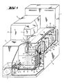
- FIG. 1 shows the outer outline of the device according to the invention, hereinafter referred to as "Minilab", and only to the extent necessary for understanding the invention.
- a copying or enlarging device P commonly referred to as a printer
- a so-called paper processor PP commonly referred to as a printer
- a film processor FP film processor
- a film and paper dryer D and a chemical supply and disposal part R are arranged in a common light-tight housing G.
- all components are per se standard. All that is new is their mutual arrangement and various details, which are explained in more detail below.
- the printer P Only the elements important for understanding the invention are shown by the printer P. These are a copying light source 1 (here physically attached to the film processor FP), a film stage 2 for positioning the film to be copied in the imaging beam path 3, an imaging optics 4, a paper stage 5 for positioning the photographic copying material K, a knife 6 for cutting off individual ones Scroll B from the copy material K located in a paper cassette 7 and rolled up into a roll.
- the paper cassette 7 is in can be coupled to and disconnected from the printer P in a known manner.
- the paper processor PP which is also conventional per se, has a series of treatment tanks 15-17, 17a arranged one behind the other, through which the individual exposed copy material sheets are passed in a known manner in a meandering path 18. Of the means of transport necessary for this, only a few transport rollers 19-23, 23a are indicated schematically in the drawing.
- the developed sheets leave the paper processor PP at its outlet 24 and from there directly into the dryer D, where they can be removed after drying.
- all functions run automatically under the control of an electronic control.
- the structure and mode of operation of the film processor FP, the dryer D and the preparation and disposal part R are irrelevant to the present invention and therefore do not require any special explanation.
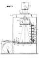
- the central point of the mini-lab according to the invention is the already mentioned sheet turner ST.
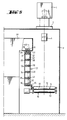
- This consists essentially of a roller rack (FIG. 3, 5) comprising (in this case) twelve rollers 31-42 arranged in pairs, which is arranged to be pivotable about a vertical axis A through an angle ⁇ 'of 90 ° (FIG. 1).
- the rollers 37-42 located on the same rack side are kinematically connected via a (toothed) belt 43.
- a swivel drive (motor or magnet) 44 is provided for pivoting the roller rack (FIG. 4).
- its rollers 31-42 are located parallel to the transport rollers 8-14 of the printer P, in the other pivot position they are parallel to the transport rollers 19-23 of the paper processor PP.
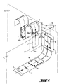
- the transport planes of the printer P and the paper processor PP are designated by t 1 and t 2.
- the transport paths of the copy material sheets are shown for clarification as (in reality, of course, nonexistent) belts b1 and b2.
- the transport planes t1 and t2 are each spanned by any movement direction vector r1 or r2 and by any normal n1 or n2 on the transport paths b1 and b2.
- r1 or r2 are each spanned by any movement direction vector r1 or r2 and by any normal n1 or n2 on the transport paths b1 and b2.
- n1 or n2 on the transport paths b1 and b2.
- there are an infinite number of transport levels but obviously all of them are parallel to t1 or t2.
- it does not depend on the absolute position, but only on the mutual orientation of the transport levels t 1 and t 2.
- the printer P and the paper processor PP are arranged substantially at right angles to one another, which means that their respective transport planes t 1 and t 2 are at exactly this right angle ⁇ to one another.
- the intersection line of the two transport planes is designated by s in FIG. 2.
- the pivot axis A of the sheet turner or roller rack ST symbolized by a rectangle is arranged parallel to the cutting line s, which results in the above-mentioned movement geometry for the rollers of the sheet turner ST in relation to those of the printer P and the paper processor PP when the rollers of the sheet turner stand perpendicular to its swivel axis A.
- rollers 31-42 of the sheet turner ST in the place of which wheels, disks or the like could also be provided without further ado, do not have their own drive. Rather, depending on the position, they are coupled to the means of transport of either the printer P or the paper processor PP and are also driven by it.
- the printer P is provided with a spring-loaded drive wheel 25 which, in the position of the roller rack shown in FIG the bottom roller 42 connected coupling wheel 45 (Fig. 4) and drives it.
- a further coupling wheel 46 is rotatably connected, which in the position of the sheet turner ST shown in FIG. 4 is in engagement with a likewise spring-loaded drive wheel 26 provided on the paper processor PP (FIG. 5).
- the two drive wheels 25 and 26 are each in kinematic connection with the transport rollers of the printer P or the paper processor PP and rotate accordingly.
- the sheet turner ST establishes the connection between the printer P and the paper processor PP. In its swivel position shown in FIGS. 1 and 3, it picks up one sheet of exposed printing material from printer P (between the transport rollers 12 and 14 vertically emerging upwards) and is in its other swivel position shown in FIGS. 4 and 5 to the paper processor PP, where it is captured and transported by means of its pair of inlet rollers 19/20.
- the ST sheet turner which is designed to be light-tight, fulfills other important functions. On the one hand, it acts as a buffer memory between the printer P and the paper processor PP and decouples these two components in terms of the work cycle. The copy material is usually transported much faster in the printer than in the paper processor.
- the input 27 of the paper processor PP is located above the copying level 5 of the printer and opens downward. This can result in any Chemical vapors are prevented from entering the sensitive printer room.
- the low-lying arrangement of the copying plane 5 enables the exposure from top to bottom with a straight, undisturbed exposure beam path, which is preferred for many reasons, and the arrangement of the paper cassette 7 on the floor desired for the operator (for reasons of weight).
- the sheet turner ST now not only effects the redirection of the exposed copy material sheets due to the right-angled arrangement of printer and paper processor, but at the same time also bridges the level difference between printer and paper processor, which is also favorable due to the high arrangement of the paper processor which is also desirable and desirable for other reasons.
- the ST sheet turner has another important function.
- the copying material K lies in the printer P with the light-sensitive layer side up, which is indicated in FIG. 2 by the full dots 50.
- the back of the copying material is symbolized by rings 51.
- the paper processor PP it has proven to be advantageous if the photographic material is guided in such a way that it lies in the individual treatment tanks with its layer side facing outwards, that is to say the layer side faces the tank walls. With conventional minilabs, both requirements could not be met at the same time. This means that if the printer was used to print from top to bottom, the copy material in the paper processor ran with the layer side inwards. However, if the copy material in the paper processor was in the desired position, the reverse beam path, i.e. from bottom to top, was required in the printer. However, the latter is disadvantageous for the reasons mentioned above.
- the sheet turner ST according to the invention now eliminates this difficulty in a very simple manner by automatically turning the copy material sheets in such a way that they pass them on to the paper processor PP in the correct orientation.
Landscapes
- Physics & Mathematics (AREA)
- General Physics & Mathematics (AREA)
- Projection-Type Copiers In General (AREA)
- Photographic Processing Devices Using Wet Methods (AREA)
Applications Claiming Priority (2)
| Application Number | Priority Date | Filing Date | Title |
|---|---|---|---|
| CH2752/87 | 1987-07-21 | ||
| CH275287 | 1987-07-21 |
Publications (2)
| Publication Number | Publication Date |
|---|---|
| EP0300967A1 EP0300967A1 (de) | 1989-01-25 |
| EP0300967B1 true EP0300967B1 (de) | 1992-08-26 |
Family
ID=4240814
Family Applications (1)
| Application Number | Title | Priority Date | Filing Date |
|---|---|---|---|
| EP88810482A Expired - Lifetime EP0300967B1 (de) | 1987-07-21 | 1988-07-14 | Vorrichtung zur Herstellung von fotografischen Kopien |
Country Status (8)
| Country | Link |
|---|---|
| US (1) | US4864355A (da) |
| EP (1) | EP0300967B1 (da) |
| JP (1) | JP2732071B2 (da) |
| BR (1) | BR8803634A (da) |
| CA (1) | CA1298127C (da) |
| DE (1) | DE3874039D1 (da) |
| DK (1) | DK168716B1 (da) |
| ES (1) | ES2034366T3 (da) |
Families Citing this family (10)
| Publication number | Priority date | Publication date | Assignee | Title |
|---|---|---|---|---|
| IT231956Y1 (it) * | 1993-02-18 | 1999-08-10 | San Marco Imaging Srl | Macchina combinata per sviluppare e stampare materiale fotografico in modo continuo ed automatico |
| JP2812143B2 (ja) * | 1993-06-15 | 1998-10-22 | ノーリツ鋼機株式会社 | 感光材料整列装置 |
| USD366272S (en) | 1994-07-08 | 1996-01-16 | Fuji Photo Film Co., Ltd. | Combined photographic printer and film processor |
| IT1278337B1 (it) * | 1994-09-19 | 1997-11-17 | Durst Phototechnik Spa | Disposizione per la messa in tensione di materiale bobinato. |
| JPH095976A (ja) * | 1995-06-20 | 1997-01-10 | Noritsu Koki Co Ltd | 写真焼付装置 |
| JP2765652B2 (ja) * | 1995-10-25 | 1998-06-18 | ノーリツ鋼機株式会社 | 感光材料整列装置 |
| JP3663821B2 (ja) * | 1997-04-11 | 2005-06-22 | ノーリツ鋼機株式会社 | 感光材料搬送装置 |
| JPH1165078A (ja) * | 1997-08-22 | 1999-03-05 | Fuji Photo Film Co Ltd | 感光材料処理装置 |
| DE29718125U1 (de) * | 1997-10-13 | 1997-11-20 | Gretag Imaging Ag, Regensdorf | Fotolabor mit Weitergabeeinrichtung |
| JP2005062285A (ja) * | 2003-08-20 | 2005-03-10 | Fuji Photo Film Co Ltd | 画像形成装置、画像形成装置のセットアップシステム、および画像形成装置のセットアップ方法 |
Family Cites Families (8)
| Publication number | Priority date | Publication date | Assignee | Title |
|---|---|---|---|---|
| US3308717A (en) * | 1964-02-19 | 1967-03-14 | Minolta Camera Kk | Enlarging and printing machine |
| CH492551A (de) * | 1967-07-06 | 1970-06-30 | Hell Rudolf Dr Ing Fa | Vorrichtung zur Steuerung des Photomaterialdurchlaufs in einem mit einer automatisch arbeitenden Entwicklungsanlage zusammenarbeitenden elektronischen Lichtsetzgerät |
| US3987465A (en) * | 1974-09-09 | 1976-10-19 | Log Etronics Inc. | Automatic camera/processor system with film turnover |
| JPS53149332A (en) * | 1977-06-01 | 1978-12-26 | Oriental Photo Ind Co Ltd | Sheettshaped photographic paper guiding device |
| US4405227A (en) * | 1979-02-09 | 1983-09-20 | Canon Kabushiki Kaisha | Photographic apparatus |
| EP0075300B1 (de) * | 1981-09-18 | 1986-01-02 | Heinrich Huss | Vorrichtung zum Zuführen fotografischer Schichtträger zu einer Entwicklungsmaschine |
| DE3205739C2 (de) * | 1981-09-18 | 1986-06-05 | Heinrich 6054 Rodgau Huss | Vorrichtung zum Zuführen fotografischer Schichtträger zu einer Entwicklungsmaschine |
| JPS603847U (ja) * | 1983-06-20 | 1985-01-12 | 日本電産コパル株式会社 | 乳剤面損傷防止用印画紙表裏面反転装置 |
-
1988
- 1988-07-14 ES ES198888810482T patent/ES2034366T3/es not_active Expired - Lifetime
- 1988-07-14 EP EP88810482A patent/EP0300967B1/de not_active Expired - Lifetime
- 1988-07-14 DE DE8888810482T patent/DE3874039D1/de not_active Expired - Fee Related
- 1988-07-19 CA CA000572395A patent/CA1298127C/en not_active Expired - Lifetime
- 1988-07-20 DK DK405688A patent/DK168716B1/da not_active IP Right Cessation
- 1988-07-20 US US07/221,741 patent/US4864355A/en not_active Expired - Lifetime
- 1988-07-20 BR BR8803634A patent/BR8803634A/pt not_active IP Right Cessation
- 1988-07-21 JP JP63182763A patent/JP2732071B2/ja not_active Expired - Fee Related
Also Published As
| Publication number | Publication date |
|---|---|
| EP0300967A1 (de) | 1989-01-25 |
| DK405688D0 (da) | 1988-07-20 |
| DE3874039D1 (de) | 1992-10-01 |
| JP2732071B2 (ja) | 1998-03-25 |
| DK405688A (da) | 1989-01-22 |
| US4864355A (en) | 1989-09-05 |
| BR8803634A (pt) | 1989-02-08 |
| ES2034366T3 (es) | 1993-04-01 |
| JPS6440945A (en) | 1989-02-13 |
| CA1298127C (en) | 1992-03-31 |
| DK168716B1 (da) | 1994-05-24 |
Similar Documents
| Publication | Publication Date | Title |
|---|---|---|
| DE69528404T2 (de) | Zubringervorrichtung von photographischem Material | |
| DE3546069C2 (da) | ||
| EP0300967B1 (de) | Vorrichtung zur Herstellung von fotografischen Kopien | |
| EP0043508B1 (de) | Vorrichtung für den Transport und die Positionierung von Druckplatten | |
| DE68901947T2 (de) | Druckapparat. | |
| DE3516746A1 (de) | Aufzeichnungsgeraet | |
| DE2164163A1 (de) | Maschinensteuerung | |
| EP0157325B1 (de) | Fotografisches Rollenkopiergerät | |
| DE2760089C2 (de) | Kopierpapierzufuhrvorrichtung für ein photographisches Kopiergerät | |
| DE69414302T2 (de) | Photographische Verarbeitungsvorrichtung | |
| CH623939A5 (da) | ||
| DE69426949T2 (de) | Verfahren und Vorrichtung zur Entwicklung von lichtempfindlichem Material | |
| DE4317918C2 (de) | Bildabzugsvorrichtung | |
| DE69226428T2 (de) | Automatische vergrösserung- und entwicklungsvorrichtung für 3d stereoskopische und normale bildern | |
| EP1229396A1 (de) | Vorrichtung zum Ausrichten von flexiblen blattförmigen Bedruckstoffen | |
| DE1447917C3 (de) | Vorrichtung zur Flüssigkeitsbehandlung von belichteten Offset-Druckplatten | |
| EP0011851B1 (de) | Vorrichtung zum Belichten und Entwickeln von lichtempfindlichem Material | |
| DE2652069B2 (de) | Vorrichtung zum elektrographischen Herstellen einer Platte für den Offsetdruck | |
| DE1597083C3 (de) | Belichtungsvorrichtung | |
| DE69418809T2 (de) | Fotografische Entwicklungsmaschine | |
| DE69530560T2 (de) | Vorratsbehälter für Filmpatronen | |
| DE3782400T2 (de) | Photographisches geraet mit filmfoerder- und behandlungsvorrichtung. | |
| DE4038307C2 (de) | Einrichtung zum Transportieren von Aufzeichnungsblättern in einer Bilderzeugungseinrichtung zum Herstellen einer beidseitigen Kopie | |
| DE2105237C3 (de) | Elektrophotographische Kopiermaschine und in einer solchen Maschine anzuwendendes, schachteiförmiges Magazin | |
| DE1182951B (de) | Vorrichtung zum Entladen und Beladen von Filmkassetten |
Legal Events
| Date | Code | Title | Description |
|---|---|---|---|
| PUAI | Public reference made under article 153(3) epc to a published international application that has entered the european phase |
Free format text: ORIGINAL CODE: 0009012 |
|
| 17P | Request for examination filed |
Effective date: 19880716 |
|
| AK | Designated contracting states |
Kind code of ref document: A1 Designated state(s): CH DE ES FR GB IT LI |
|
| 17Q | First examination report despatched |
Effective date: 19911121 |
|
| GRAA | (expected) grant |
Free format text: ORIGINAL CODE: 0009210 |
|
| AK | Designated contracting states |
Kind code of ref document: B1 Designated state(s): CH DE ES FR GB IT LI |
|
| REF | Corresponds to: |
Ref document number: 3874039 Country of ref document: DE Date of ref document: 19921001 |
|
| ET | Fr: translation filed | ||
| ITF | It: translation for a ep patent filed | ||
| GBT | Gb: translation of ep patent filed (gb section 77(6)(a)/1977) | ||
| REG | Reference to a national code |
Ref country code: ES Ref legal event code: FG2A Ref document number: 2034366 Country of ref document: ES Kind code of ref document: T3 |
|
| PLBE | No opposition filed within time limit |
Free format text: ORIGINAL CODE: 0009261 |
|
| STAA | Information on the status of an ep patent application or granted ep patent |
Free format text: STATUS: NO OPPOSITION FILED WITHIN TIME LIMIT |
|
| ITTA | It: last paid annual fee | ||
| 26N | No opposition filed | ||
| REG | Reference to a national code |
Ref country code: CH Ref legal event code: PVP Owner name: QUALEX INC. |
|
| REG | Reference to a national code |
Ref country code: CH Ref legal event code: PUE Owner name: GRETAG AKTIENGESELLSCHAFT TRANSFER- GRETAG IMAGING |
|
| REG | Reference to a national code |
Ref country code: GB Ref legal event code: 732E |
|
| REG | Reference to a national code |
Ref country code: ES Ref legal event code: PC2A Owner name: GRETAG IMAGING AG |
|
| REG | Reference to a national code |
Ref country code: FR Ref legal event code: TP |
|
| REG | Reference to a national code |
Ref country code: CH Ref legal event code: PVP |
|
| REG | Reference to a national code |
Ref country code: GB Ref legal event code: 732E |
|
| REG | Reference to a national code |
Ref country code: FR Ref legal event code: GC |
|
| REG | Reference to a national code |
Ref country code: GB Ref legal event code: IF02 |
|
| REG | Reference to a national code |
Ref country code: GB Ref legal event code: 732E |
|
| PGFP | Annual fee paid to national office [announced via postgrant information from national office to epo] |
Ref country code: GB Payment date: 20030704 Year of fee payment: 16 |
|
| PGFP | Annual fee paid to national office [announced via postgrant information from national office to epo] |
Ref country code: CH Payment date: 20030708 Year of fee payment: 16 |
|
| PGFP | Annual fee paid to national office [announced via postgrant information from national office to epo] |
Ref country code: DE Payment date: 20030710 Year of fee payment: 16 |
|
| PGFP | Annual fee paid to national office [announced via postgrant information from national office to epo] |
Ref country code: FR Payment date: 20030711 Year of fee payment: 16 |
|
| PGFP | Annual fee paid to national office [announced via postgrant information from national office to epo] |
Ref country code: ES Payment date: 20030717 Year of fee payment: 16 |
|
| PG25 | Lapsed in a contracting state [announced via postgrant information from national office to epo] |
Ref country code: GB Free format text: LAPSE BECAUSE OF NON-PAYMENT OF DUE FEES Effective date: 20040714 |
|
| PG25 | Lapsed in a contracting state [announced via postgrant information from national office to epo] |
Ref country code: ES Free format text: LAPSE BECAUSE OF NON-PAYMENT OF DUE FEES Effective date: 20040715 |
|
| PG25 | Lapsed in a contracting state [announced via postgrant information from national office to epo] |
Ref country code: LI Free format text: LAPSE BECAUSE OF NON-PAYMENT OF DUE FEES Effective date: 20040731 Ref country code: CH Free format text: LAPSE BECAUSE OF NON-PAYMENT OF DUE FEES Effective date: 20040731 |
|
| PG25 | Lapsed in a contracting state [announced via postgrant information from national office to epo] |
Ref country code: DE Free format text: LAPSE BECAUSE OF NON-PAYMENT OF DUE FEES Effective date: 20050201 |
|
| GBPC | Gb: european patent ceased through non-payment of renewal fee |
Effective date: 20040714 |
|
| REG | Reference to a national code |
Ref country code: CH Ref legal event code: PL |
|
| PG25 | Lapsed in a contracting state [announced via postgrant information from national office to epo] |
Ref country code: FR Free format text: LAPSE BECAUSE OF NON-PAYMENT OF DUE FEES Effective date: 20050331 |
|
| REG | Reference to a national code |
Ref country code: FR Ref legal event code: ST |
|
| PG25 | Lapsed in a contracting state [announced via postgrant information from national office to epo] |
Ref country code: IT Free format text: LAPSE BECAUSE OF NON-PAYMENT OF DUE FEES;WARNING: LAPSES OF ITALIAN PATENTS WITH EFFECTIVE DATE BEFORE 2007 MAY HAVE OCCURRED AT ANY TIME BEFORE 2007. THE CORRECT EFFECTIVE DATE MAY BE DIFFERENT FROM THE ONE RECORDED. Effective date: 20050714 |
|
| REG | Reference to a national code |
Ref country code: ES Ref legal event code: FD2A Effective date: 20040715 |