EP0288881B1 - Sortierer - Google Patents
Sortierer Download PDFInfo
- Publication number
- EP0288881B1 EP0288881B1 EP88106236A EP88106236A EP0288881B1 EP 0288881 B1 EP0288881 B1 EP 0288881B1 EP 88106236 A EP88106236 A EP 88106236A EP 88106236 A EP88106236 A EP 88106236A EP 0288881 B1 EP0288881 B1 EP 0288881B1
- Authority
- EP
- European Patent Office
- Prior art keywords
- sheet material
- delivering unit
- conveying means
- gripping
- bin
- Prior art date
- Legal status (The legal status is an assumption and is not a legal conclusion. Google has not performed a legal analysis and makes no representation as to the accuracy of the status listed.)
- Expired
Links
Images


Classifications
-
- B—PERFORMING OPERATIONS; TRANSPORTING
- B65—CONVEYING; PACKING; STORING; HANDLING THIN OR FILAMENTARY MATERIAL
- B65H—HANDLING THIN OR FILAMENTARY MATERIAL, e.g. SHEETS, WEBS, CABLES
- B65H39/00—Associating, collating, or gathering articles or webs
- B65H39/10—Associating articles from a single source, to form, e.g. a writing-pad
- B65H39/11—Associating articles from a single source, to form, e.g. a writing-pad in superposed carriers
-
- B—PERFORMING OPERATIONS; TRANSPORTING
- B65—CONVEYING; PACKING; STORING; HANDLING THIN OR FILAMENTARY MATERIAL
- B65H—HANDLING THIN OR FILAMENTARY MATERIAL, e.g. SHEETS, WEBS, CABLES
- B65H2408/00—Specific machines
- B65H2408/10—Specific machines for handling sheet(s)
- B65H2408/11—Sorters or machines for sorting articles
- B65H2408/112—Sorters or machines for sorting articles with stationary location in space of the bins and in-feed member movable from bin to bin
Definitions
- first and second sheet material gripping and conveying means as the sheet material delivering means
- the second sheet material gripping and conveying means is also returned to the predetermined position after it transfers the sheet material to the first sheet material gripping and conveying means, and the sheet material conveying speed V R of the second sheet material gripping and conveying means during the returning stroke is substantially equal to a sum (V1+V2) of the sheet material conveying speed V1 of the first sheet material gripping and conveying means and the returning speed V2 of the second sheet material conveying means; or, the sheet gripping and conveying force of the second sheet material gripping and conveying means is released.
- Figure 3 is a perspective view of a vertical driving mechanism for first and second delivering units.
- Figures 4A, 4B and 4C are front, left side and cross-sectional view partly broken, of a delivering unit.
- Figures 5A and 5B are a plan view and a sectional view partly broken in the state where the first delivering unit is opposed to a predetermined bin position, and the second delivering unit is opposed to the first delivering unit.
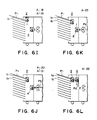
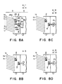
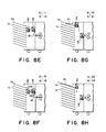
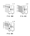
- Figures 6A - 6N illustrate an operation of the sorter.
- FIGS 8A - 8O illustrate an operation of a sorter according to a further embodiment of the invention.
- FIG. 2 there is shown a general arrangement of an electrophotographic copying machine as an exemplary sheet material discharging device A and a sorter as an exemplary sheet material distributing device B according to an embodiment of the present invention attached thereto at the sheet material discharging side.
- the structure and image forming process of the copying machine A may be of a known type, and therefore, the detailed description thereof is omitted.
- the main apparatus comprises a fixed platen glass (an original supporting glass) 71, an original pressing plate 72, an original scanning mechanism of a movable optical system type including an original illuminating lamp, a movable mirror, an imaging lens and fixed mirrors, a rotatable photosensitive drum 74, a charger 75, a developing device 76, a transfer and separation charger 77, a cleaning device 78, first and second transfer sheet material accommodating cassettes 79 and 80, a sheet conveying device 81, an image fixing device 82, a sheet material discharging rollers 83 and a sheet material discharging outlet 70 for discharging copies.
- the sorter B is provided with a plurality of bins 1a - 1j which are stationary and are arranged vertically.
- the sorter B includes a first sheet material gripping and conveying means 2 (which will hereinafter be called “first delivering unit”) which is vertically movable relative to a sheet material inlet side of each of the bins 1a - 1j, and a second sheet material gripping and conveying means 4 (which hereinafter be called “second delivering unit) which functions to receive the sheet material discharged from the sheet material discharging outlet 70 of the main apparatus A and to transfer the sheet material to the first delivering unit 2, the second delivering unit 4 being vertically movable.
- first delivering unit which is vertically movable relative to a sheet material inlet side of each of the bins 1a - 1j
- second sheet material gripping and conveying means 4 which functions to receive the sheet material discharged from the sheet material discharging outlet 70 of the main apparatus A and to transfer the sheet material to the first delivering unit 2, the second delivering unit
- the vertical movement mechanism for the first delivering unit 2 includes a pair of main shafts 31 and 32 which are journalled parallel at lower and upper portions of the sorter B, pulleys 33, 33; 34, 34 mounted to the main shafts 31 and 32 at the front and rear portions, a pair of belts 35 and 35 which extend vertically at front and rear portions and which are entrained on the pulleys 33 and 34, 33 and 34, a driving pulley 36 mounted to a rear side end portion of the lower main shaft 31, a reversible motor M1 for the vertical movement, a driving pulley 37 entrained on the output shaft of the motor M1 and a belt 38 entrained on the driving pulley 37 and the pulley 36 for receiving the driving force.
- the first delivering unit 2 is supported on the belt 35 substantially horizontally by fixing its side plates 20 and 20 to the vertical belts 35 and 35.
- the moving mechanism (51 - 59, M2, 40, 41) is of substantially the same structure as the first delivering unit 2 in this embodiment.
- the vertical movement motor M2 When the vertical movement motor M2 is rotated forwardly, a pair of belts 55 and 55 rotates forwardly, by which the second delivering unit 4 moves upwardly.
- the motor M2 When, on the contrary, the motor M2 is driven backwardly, a pair of belts 55 and 55 rotates backwardly, by which the unit 4 moves downwardly.
- the first delivering unit 2 detects the position of each of the bins by counting flags M projected at the sheet material inlet sides of the bins by the sensor 30 during the upward or downward movement thereof. Therefore, the first delivering unit 2 is moved, controlled and positioned precisely at a position corresponding to each of the sheet material inlets.
- the second delivering unit 4 detects by the sensor 50 the flags n projected at the first delivering unit side thereof during the upwardly or downward movement thereof, by which it is precisely moved, controlled and positioned at a position corresponding to the first delivering unit 2.
- A-1 An original is placed on the platen glass 71 of the main apparatus A (copying apparatus), and desired sorting mode conditions are set on an operation panel to input them into a control circuit. Then, a start key is depressed.
- the sorter B In response to the depression of the start key, the sorter B is prepared for operation (stand-by). More particularly, the discrimination is made as to (1) whether or not the first delivering unit 2 is placed at a predetermined home position which in this embodiment corresponds to the sheet material inlet of the topmost bin 1a, and (2) whether or not the second delivering unit 4 is placed at its home position in which it is opposed to the sheet material discharge outlet 70 of the main apparatus A.
- the discrimination is made by a control circuit on the basis of signals from unshown detecting means such as microswitches or the like which are actuated when the units 2 and 4 are placed at their home positions.
- A-3 When one or all of the first and second delivering units 2 and 4 are not placed at the home positions, one or all of the vertical movement motors M1 and M2 ( Figure 3) are forwardly or backwardly driven to return the unit or units 2 and 4 to the home position(s) (initial setting) ( Figure 6A).
- A-4 When the stand-by operation (A-1 - A-3) of the sorter B is completed, the main apparatus A starts the copying operation.
- a first sheet material P1 having been processed for image formation in the main apparatus A is introduced into the sorter B from the discharging roller couple 83 through the discharging outlet 70.
- the vertical movement motor M2 for the second delivering unit 4 is rotated forwardly to upwardly move the unit 4 while gripping the leading end portion of the sheet material P1 between the rollers 44 and 45 ( Figures 6D - 6E). That is, the sheet material P1 is conveyed upwardly.
- the upward movement speed of the unit 4 is substantially the same as or a little lower than the discharging speed of the sheet material P1 from the discharge outlet 70 of the main apparatus A, and therefore, the sheet material is not stretched or bent or is not imparted by an excessive load between the roller couple (44 and 45) and the discharging roller couple 83.
- the sheet material P1 is conveyed upwardly with a proper loop.
- A-13 The leading edge of the sheet material P1 is guided by the guiding plates 22 and 22 and is introduced into the nip formed between the rollers 24 and 25 of the first delivering unit 2.
- the pressure by the rollers 24 and 25 is made same as or higher than the pressure by the rollers 44 and 45 of the secondary delivering unit 4, so that the leading edge portion of the sheet material P1 is caught by the rollers 24 and 25 with certainty.
- A-15 When the leading edge of the sheet material P1 which has been introduced into the first delivering unit 2 and advanced between the rollers 24 and 25 is detected by the sensors 29a and 29b for detecting the presence of the sheet material, the detecting signal starts a reverse rotation of the vertical movement motor M2 for the second delivering unit 4, so that the unit 4 starts to move downwardly. At this point of time, the leading edge of the sheet material P1 is sufficiently gripped by the nip between the rollers 24 and 25 of the first delivering unit 2, and the sheet material P1 is transferred from the second delivering unit 4 to the first delivering unit 2 with certainty.
- the high speed rotational speed V R of the roller 44 that is, the sheet conveying speed of the second delivering unit 4 during the returning movement is made substantially equal to a sum (V1+V2) of the sheet material conveying speed V11 by the rollers 24 and 25 of the first delivering unit 2 and the lowering speed (returning speed) V2 of the second delivering unit 4. Therefore, even if the sheet material P1 is still passing through the second delivering unit 4 and is not yet completely released therefrom, the lowering movement of the unit 4 does not result in substantial load such as tension, friction or bending force or the like to the sheet material portion between the units, or the load is significantly reduced.
- the returning speed V2 of the second delivering unit 4 to its home position is preferably as high as possible, because the next sheet material can be received not in haste, so that the conveyance can be performed securedly.
- the sheet material P1 transferred to the first delivering unit 2 is discharged onto the topmost bin 1a to which the unit 2 is opposed, by the forward rotation of the rollers 24 and 25 of the first delivering unit 2.
- the vertical movement motor M1 of the first delivering unit is rotated backwardly, so that the lowering movement of the unit 2 starts ( Figure 6I).
- the lowering speed speed of the unit 2 is preferably as high as possible.
- A-20 When the arrival of the first delivering unit 2 moving downwardly at a position corresponding to the sheet material inlet of the next stage bin 1b, is detected by the flag m and the sensor 30 ( Figure 5), the backward movement of the vertical movement motor M1 is stopped instantaneously, and the unit 4 is retained at a position corresponding to the sheet material inlet of the next bin 1b ( Figure 6J).
- a second sheet P2 is discharged from the main apparatus A and is introduced into the sorter B.
- A-23 The second sheet material P2 is discharged onto the second bin 1b since the first delivering unit 2 is opposed to the second bin 1b counted from the top.
- the sheet materials are sequentially distributed or sorted to the plural bins.
- the copy sheets from the first original are first distributed in the manner described above to bins 1a - 1j (from the first bin to the tenth bin).
- the copy sheets from the second original are distributed to bins 1j -1a (from the tenth bin to the first bin), that is, in the reverse order.
- the copy sheets from the third original are distributed in the order from the first bin 1a to the tenth bin 1j. By doing so, the sorting operation is performed efficiently.
- a predetermined number of second and subsequent sheet materials discharged from the main apparatus A are discharged onto the topmost bin 1a by repeating the operational steps A-5 - A-18.
- the first delivering unit similarly to the step A-20, is stopped at a position where it is opposed to the sheet material inlet of the second bin 1b.
- the first delivering unit 2 is lowered by the amount corresponding to one stage of the bins.
- the sheet materials can be distributed in the collation mode for each of the bins down to the bottommost bin 1j.
- C-2 The operations A-5 - A-18 in the sorting mode and B-3 and B-4 in the collation mode, are repeated, by which all the sheet materials discharged from the main apparatus A are discharged onto the topmost bin 1a.
- the sheet material conveying speed of the first and second delivering units 2 and 4 is preferably near the discharging speed of the sheet material from the main apparatus A, from the standpoint of not imparting load to the sheet material.
- the sheet material conveying speed of the first delivering unit 2 may be increased. Additionally, passage of the trailing edge of the sheet material through the image fixing device 82 or through the discharging roller couple 83 in the main apparatus A may be detected by a sensor S1 ( Figure 2) in the main apparatus A, and in response to which the sheet conveying speed of the first and second delivering units 2 and 4 of the sorter B may be increased.
- D-1 The stand-by operation is performed in the similar manner as with A-1 - A-3 in the sorting mode.
- the main apparatus A instructs that the second sheet material is discharged onto the bottommost bin tray 1j, for example.
- the bottommost bin 1j is taken as an example, and may be any one of the bins 1a - 1j.
- the sensors 29a and 29b of the first delivering unit 2 detects that the first sheet material is discharged to the topmost bin 1a, the vertical movement motor M1 of the first delivering unit 2 is rotated backwardly, so that the unit 2 lowers immediately toward the bin 1j.
- the second delivering unit 4 is returned to its home position corresponding to the sheet material discharge outlet 70 of the main apparatus A, by the operation A-17 in the sorting mode, and it waits for the second sheet material to be discharged.
- the sheet materials are distributed in accordance with the instructions from the main apparatus A for each of the sheet materials (random mode).
- the time period required for the sheet material to be transferred from the second delivering unit 4 to the first delivering units 2 can be spent for the movement of the first delivering unit 2 to the next bin, and therefore, the amount of movement of the delivering unit can be increased as compared with the conventional machines, and therefore, it is made possible that the intervals between adjacent bins can be increased to increase the sheet stacking capacity of each of the bins, or it is made possible to increase the number of total bins.
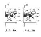
- FIGS 7A and 7B illustrate an example of a mechanism for effecting such releasing.
- the second delivering unit 4 is provided with a lever 92 swingably controlled about a shaft 91 by a solenoid-plunger 90.
- the free end of the lever 92 is engaged with a leaf spring 46 for press-contacting the roller 45 to the roller 44.
- a lever resetting spring 93 is provided.
- the solenoid 90 When the second delivering unit 4 is in the returning stroke, the solenoid 90 is energized to release the sheet material from the sheet material gripping and conveying force of the unit 4. When the unit 4 reaches the home position, the solenoid 90 is deenergized, so that the sheet gripping and conveying force is reset.
- the feature of the third embodiment is in that the second delivering unit 4 is reciprocated only between its home position and the home position of the first delivering unit 2, so that the reciprocating stroke is constant, and by property setting the home position of the first delivering unit, the reciprocating stroke can be relatively short.
- the position where the first delivering unit 2 receives the sheet material from the second delivering unit 4, is always constant.
- A-1 A start key is depressed.
- the sorter B In response to the depression of the start key, the sorter B is prepared for operation (stand-by). More particularly, the discrimination is made as to (1) whether or not the first delivering unit 2 is placed at a predetermined home position which in this embodiment corresponds to the position of the third bin 1c as counted from the top which is substantially at the middle between the topmost bin 1a and the sheet discharging outlet of the main apparatus A, and (2) whether or not the second delivering unit 4 is placed at its home position in which it is opposed to the sheet material discharge outlet 70 of the main apparatus A.
- the discrimination is made by a control circuit on the basis of signals from unshown detecting means such as microswitches or the like which are actuated when the units 2 and 4 are placed at their home positions.
- A-3 When one or all of the first and second delivering units 2 and 4 are not placed at the home positions, one or all of the vertical movement motors M1 and M2 ( Figure 3) are forwardly or backwardly driven to return the unit or units 2 and 4 to the home position(s) (initial setting) ( Figure 8A).
- A-4 When the stand-by operation (A-1 - A-3) of the sorter B is completed, the main apparatus A starts the copying operation.
- a first sheet material P1 having been processed for image formation in the main apparatus A is introduced into the sorter B from the discharging roller couple 83 through the discharging outlet 70.
- A-7 The introduced sheet material P1 is directed to between the upper and lower guiding plates 42 and 42 of the second delivering unit 4 which is maintained at its home position opposed to the discharge outlet 70, and its leading edge is guided by the guiding plates 42 and 42 and is introduced into the nip formed between the rollers 44 and 45.
- A-12 Simultaneously, the forward driving of the sheet material conveying motor m2 of the second delivering unit 4 is resumed, so that the sheet material P1 having been gripped by the nip between the rollers 44 and 45 is conveyed by the rotation of the rollers 44 and 45 to between the sheet material guiding plates 22 and 22 of the first delivering unit 2.
- A-20 Simultaneously with the stoppage of the vertical movement motor M1, the forward rotation of the sheet material conveying motor m1 is resumed, by which the sheet material P1 is started to be discharged from the first delivering unit 2 to the topmost bin 1a to which it is currently opposed.
- A-28 When the similar operations are repeated to an extent of the bin 1e (top five bins), the first delivering unit 2 is shifted to a second home position which is, in this embodiment, the eighth bin 1h as counted from the top (the third bin from the bottom) ( Figure 8N).
- the second delivering unit 4 has its home position which corresponds to the sheet material discharge outlet 70 of the main apparatus and shares the sheet material transportation from the home position to the first home position (bin 1c position) of the first delivering unit or to the second home position (bin 1h position) of the first delivering unit 2.
- the first delivering unit 2 shares the sheet material transportation from its first home position to the top five bins 1a - 1e and the sheet material transportation from the second home position to the bottom five bins 1f - 1j.
- C-1 The stand-by operation is performed in the similar manner as with A-1 - A-3 in the sorting mode.
Claims (9)
- Blattmaterial-Verteilvorrichtung, die umfaßt:
eine Mehrzahl von Schalen (1) zur Aufnahme von Blattmaterialien; eine erste Blattmaterial-Greif- und Fördereinrichtung (2), die einem Blattmaterialeinlaß einer jeden der genannten Schalen (1) gegenübergesetzt werden kann; gekennzeichnet durch
eine zweite Blattmaterial-Greif- und Fördereinrichtung (4), die verschiebbar ist, um ein Blattmaterial von einer Blattmaterial-Austragvorrichtung (83) zu empfangen und das Blattmaterial zu der besagten ersten Blattmaterial-Greif- und Fördereinrichtung (2) zu überführen. - Vorrichtung nach Anspruch 1, dadurch gekennzeichnet, daß die erste Blattmaterial-Greif- und Fördereinrichtung (2) verlagerbar ist.
- Vorrichtung nach Anspruch 1 oder 2, dadurch gekennzeichnet, daß die Schalen (1) bewegbar sind.
- Vorrichtung nach einem der Ansprüche 1 bis 3, die ferner einen Druckentlastungsmechanismus (90, 91, 92, 93) umfaßt um eine Blattmaterialgreifkraft der erwähnten zweiten Blattmaterial-Greif- und Fördereinrichtung (4) aufzuheben, wenn diese zu einer Position zum Empfang des Blattmaterials von der Blattmaterial-Austragvorrichtung (83) zurückkehrt.
- Vorrichtung nach einem der Ansprüche 1 bis 3, die ferner Mittel umfaßt, um eine Fördergeschwindigkeit VR auf V1+V2 zu regeln, wenn die erwähnte zweite Blattmaterial-Greif- und Fördereinrichtung (4) zu einer Position zum Empfang des Blattmaterials von der Blattmaterial-Austragvorrichtung (83) zurückkehrt, wobei V1 eine Blattmaterial-Fördergeschwindigkeit der besagten ersten Blattmaterial-Greif- und Fördereinrichtung (2) sowie V2 eine Rückkehrgeschwindigkeit der erwähnten zweiten Blattmaterial-Greif- und Fördereinrichtung (4) sind.
- Vorrichtung nach einem der Ansprüche 1 bis 3, die ferner Regeleinrichtungen umfaßt, um eine Bewegung der besagten ersten Blattmaterial-Greif- und Fördereinrichtung (2) für ein schrittweises, den genannten Schalen (1) entsprechendes Bewegen zu einer Position zu regeln, in der die besagte erste Blattmaterial-Greif- und Fördereinrichtung (2) das Blattmaterial von der erwähnten zweiten Blattmaterial-Greif- und Fördereinrichtung (4) empfängt.
- Vorrichtung nach einem der Ansprüche 1 bis 3, die ferner Regeleinrichtungen umfaßt, um eine Bewegung der besagten ersten Blattmaterial-Greif- und Fördereinrichtung (2) derart zu regeln, daß eine Position, in der die besagte erste Blattmaterial-Greif- und Fördereinrichtung (2) das Blattmaterial von der erwähnten zweiten Blattmaterial-Greif- und Fördereinrichtung (4) empfängt, wenigstens zwei Schalen (1) gemeinsam ist.
- Vorrichtung nach einem der Ansprüche 1 bis 3, die ferner in der besagten ersten Blattmaterial-Greif- und Fördereinrichtung (2) vorgesehene Schalenposition-Ermittlungseinrichtungen (30) sowie in der erwähnten zweiten Blattmaterial-Greif- und Fördereinrichtung (4) vorgesehene Ermittlungseinrichtungen (50), um eine Position der besagten ersten Blattmaterial-Greif- und Fördereinrichtung (2) zu ermitteln, umfaßt.
- Vorrichtung nach einem der Ansprüche 1 bis 3, die ferner Ermittlungseinrichtungen (29a, 29b), um festzustellen, daß das Blattmaterial von der besagten ersten Blattmaterial-Greif- und Fördereirnichtung (2) erfaßt ist, und Regeleinrichtugnen zur Regelung der erwähnten zweiten Blattmaterial-Greif- und Fördereinrichtung(4), um diese zu einer Position zum Empfang des Blattmaterials zurückzuführen, wenn die genannten Ermittlungseinrichtungen (29a, 29b) das Erfassen des Blattmaterials durch die besagte erste Blattmaterial-Greif- und Fördereinrichtung (2) feststellen, umfaßt.
Applications Claiming Priority (8)
| Application Number | Priority Date | Filing Date | Title |
|---|---|---|---|
| JP62096945A JPS63262374A (ja) | 1987-04-20 | 1987-04-20 | シ−ト材分配装置 |
| JP96944/87 | 1987-04-20 | ||
| JP62096946A JPS63262371A (ja) | 1987-04-20 | 1987-04-20 | シ−ト材分配装置 |
| JP62096947A JPS63262372A (ja) | 1987-04-20 | 1987-04-20 | シ−ト材分配装置 |
| JP96945/87 | 1987-04-20 | ||
| JP96946/87 | 1987-04-20 | ||
| JP62096944A JPS63262373A (ja) | 1987-04-20 | 1987-04-20 | シ−ト材分配装置 |
| JP96947/87 | 1987-04-20 |
Publications (2)
| Publication Number | Publication Date |
|---|---|
| EP0288881A1 EP0288881A1 (de) | 1988-11-02 |
| EP0288881B1 true EP0288881B1 (de) | 1992-07-22 |
Family
ID=27468491
Family Applications (1)
| Application Number | Title | Priority Date | Filing Date |
|---|---|---|---|
| EP88106236A Expired EP0288881B1 (de) | 1987-04-20 | 1988-04-19 | Sortierer |
Country Status (3)
| Country | Link |
|---|---|
| US (1) | US4900009A (de) |
| EP (1) | EP0288881B1 (de) |
| DE (1) | DE3872923T2 (de) |
Families Citing this family (82)
| Publication number | Priority date | Publication date | Assignee | Title |
|---|---|---|---|---|
| GB2185465B (en) * | 1986-01-20 | 1989-11-08 | Ricoh Kk | Sorter |
| US5273266A (en) * | 1988-12-02 | 1993-12-28 | Canon Kabushiki Kaisha | Reserving-type original feeding apparatus |
| US5110104A (en) * | 1989-05-19 | 1992-05-05 | Canon Kabushiki Kaisha | Sheet transporting device with carriage unit |
| US5255908A (en) * | 1989-10-18 | 1993-10-26 | Canon Kabushiki Kaisha | Sheet sorter with control for continuous operation |
| JPH089453B2 (ja) * | 1989-10-18 | 1996-01-31 | キヤノン株式会社 | シート分類装置 |
| DE4042358C2 (de) * | 1990-03-27 | 1997-04-30 | Helmut Steinhilber | Sortiergerät zur Ablage von blattförmigen Aufzeichnungsträgern |
| JP2638291B2 (ja) * | 1990-11-26 | 1997-08-06 | 三田工業株式会社 | 用紙搬送ジョイント機構 |
| JP3500164B2 (ja) * | 1992-05-19 | 2004-02-23 | 理想科学工業株式会社 | 孔版印刷装置 |
| US5455667A (en) * | 1992-09-16 | 1995-10-03 | Canon Kabushiki Kaisha | Sheet handling apparatus with plural sheet storage units |
| JP3227220B2 (ja) * | 1992-09-24 | 2001-11-12 | キヤノン株式会社 | シート後処理装置 |
| US5492315A (en) * | 1993-02-07 | 1996-02-20 | Canon Kabushiki Kaisha | Sheet post-treatment apparatus having tab trimmer |
| JPH06286936A (ja) * | 1993-04-07 | 1994-10-11 | Canon Inc | ジャム処理容易なシート後処理装置 |
| JP3696893B2 (ja) * | 1993-04-07 | 2005-09-21 | キヤノン株式会社 | シート束移送手段を備えるシート後処理装置 |
| US5326093A (en) * | 1993-05-24 | 1994-07-05 | Xerox Corporation | Universal interface module interconnecting various copiers and printers with various sheet output processors |
| US5540421A (en) * | 1993-07-30 | 1996-07-30 | Canon Kabushiki Kaisha | Book binding apparatus |
| JP2750269B2 (ja) * | 1993-12-20 | 1998-05-13 | キヤノン株式会社 | シート搬送装置及びシート仕分け収納装置 |
| US5695189A (en) | 1994-08-09 | 1997-12-09 | Shuffle Master, Inc. | Apparatus and method for automatically cutting and shuffling playing cards |
| US20020063389A1 (en) * | 1994-08-09 | 2002-05-30 | Breeding John G. | Card shuffler with sequential card feeding module and method of delivering groups of cards |
| US7584962B2 (en) * | 1994-08-09 | 2009-09-08 | Shuffle Master, Inc. | Card shuffler with jam recovery and display |
| US5692747A (en) * | 1995-04-27 | 1997-12-02 | Hewlett-Packard Company | Combination flipper sorter stacker and mail box for printing devices |
| FR2751315B1 (fr) * | 1996-07-22 | 1999-03-12 | Canon Kk | Dispositif et procede de manipulation de feuille |
| US6676127B2 (en) | 1997-03-13 | 2004-01-13 | Shuffle Master, Inc. | Collating and sorting apparatus |
| IT1296904B1 (it) * | 1997-12-24 | 1999-08-02 | Edue Italia Spa | Accumulatore-erogatore di una striscia di carta di lunghezza variabile uscente da una stampante |
| US7255344B2 (en) | 1998-04-15 | 2007-08-14 | Shuffle Master, Inc. | Device and method for continuously shuffling and monitoring cards |
| US6655684B2 (en) * | 1998-04-15 | 2003-12-02 | Shuffle Master, Inc. | Device and method for forming and delivering hands from randomly arranged decks of playing cards |
| US6254096B1 (en) * | 1998-04-15 | 2001-07-03 | Shuffle Master, Inc. | Device and method for continuously shuffling cards |
| CA2364413C (en) * | 1998-04-15 | 2012-03-20 | Shuffle Master, Inc. | Device and method for continuously shuffling and monitoring cards |
| US6149154A (en) * | 1998-04-15 | 2000-11-21 | Shuffle Master Gaming | Device and method for forming hands of randomly arranged cards |
| US20020163125A1 (en) * | 1998-04-15 | 2002-11-07 | Shuffle Master, Inc. | Device and method for continuously shuffling and monitoring cards for specialty games |
| US6250627B1 (en) * | 1999-03-22 | 2001-06-26 | Gradco (Japan) Ltd. | Selective sheet delivery apparatus |
| US8490973B2 (en) | 2004-10-04 | 2013-07-23 | Shfl Entertainment, Inc. | Card reading shoe with card stop feature and systems utilizing the same |
| US7946586B2 (en) * | 2000-04-12 | 2011-05-24 | Shuffle Master Gmbh & Co Kg | Swivel mounted card handling device |
| US8511684B2 (en) | 2004-10-04 | 2013-08-20 | Shfl Entertainment, Inc. | Card-reading shoe with inventory correction feature and methods of correcting inventory |
| US8590896B2 (en) | 2000-04-12 | 2013-11-26 | Shuffle Master Gmbh & Co Kg | Card-handling devices and systems |
| JP3780148B2 (ja) | 2000-05-26 | 2006-05-31 | キヤノン株式会社 | 画像形成装置 |
| US6817466B2 (en) * | 2000-11-09 | 2004-11-16 | Honeywell International, Inc. | Apparatus for manufacturing filter cartridges, and method of using same |
| US7677565B2 (en) * | 2001-09-28 | 2010-03-16 | Shuffle Master, Inc | Card shuffler with card rank and value reading capability |
| US8038521B2 (en) | 2001-09-28 | 2011-10-18 | Shuffle Master, Inc. | Card shuffling apparatus with automatic card size calibration during shuffling |
| US8616552B2 (en) | 2001-09-28 | 2013-12-31 | Shfl Entertainment, Inc. | Methods and apparatuses for an automatic card handling device and communication networks including same |
| US6651981B2 (en) | 2001-09-28 | 2003-11-25 | Shuffle Master, Inc. | Card shuffling apparatus with integral card delivery |
| RU2316372C2 (ru) * | 2001-09-28 | 2008-02-10 | Шаффл Мастер, Инк. | Устройство для тасования карт с автоматической калибровкой по размеру карт |
| US8011661B2 (en) | 2001-09-28 | 2011-09-06 | Shuffle Master, Inc. | Shuffler with shuffling completion indicator |
| US8337296B2 (en) | 2001-09-28 | 2012-12-25 | SHFL entertaiment, Inc. | Method and apparatus for using upstream communication in a card shuffler |
| US7753373B2 (en) | 2001-09-28 | 2010-07-13 | Shuffle Master, Inc. | Multiple mode card shuffler and card reading device |
| AT5678U1 (de) * | 2001-10-19 | 2002-10-25 | Card Casinos Austria Res & Dev | Kartenmischer |
| US6886829B2 (en) * | 2002-02-08 | 2005-05-03 | Vendingdata Corporation | Image capturing card shuffler |
| JP2004069770A (ja) * | 2002-08-01 | 2004-03-04 | Canon Inc | 画像形成装置 |
| US20050113166A1 (en) * | 2003-07-17 | 2005-05-26 | Shuffle Master, Inc. | Discard rack with card reader for playing cards |
| US20060066048A1 (en) * | 2004-09-14 | 2006-03-30 | Shuffle Master, Inc. | Magnetic jam detection in a card shuffler |
| US7766332B2 (en) * | 2006-07-05 | 2010-08-03 | Shuffle Master, Inc. | Card handling devices and methods of using the same |
| AU2005326902A1 (en) | 2005-02-07 | 2006-08-10 | Telefonaktiebolaget Lm Ericsson (Publ). | Plain old telephony equivalent services supported via unlicensed mobile access |
| US7764836B2 (en) * | 2005-06-13 | 2010-07-27 | Shuffle Master, Inc. | Card shuffler with card rank and value reading capability using CMOS sensor |
| US7556266B2 (en) | 2006-03-24 | 2009-07-07 | Shuffle Master Gmbh & Co Kg | Card shuffler with gravity feed system for playing cards |
| US8419016B2 (en) * | 2006-05-17 | 2013-04-16 | Shfl Entertainment, Inc. | Playing card delivery for games with multiple dealing rounds |
| US8579289B2 (en) | 2006-05-31 | 2013-11-12 | Shfl Entertainment, Inc. | Automatic system and methods for accurate card handling |
| US8353513B2 (en) | 2006-05-31 | 2013-01-15 | Shfl Entertainment, Inc. | Card weight for gravity feed input for playing card shuffler |
| US8342525B2 (en) | 2006-07-05 | 2013-01-01 | Shfl Entertainment, Inc. | Card shuffler with adjacent card infeed and card output compartments |
| US8070574B2 (en) | 2007-06-06 | 2011-12-06 | Shuffle Master, Inc. | Apparatus, system, method, and computer-readable medium for casino card handling with multiple hand recall feature |
| US8919775B2 (en) | 2006-11-10 | 2014-12-30 | Bally Gaming, Inc. | System for billing usage of an automatic card handling device |
| US7988152B2 (en) | 2009-04-07 | 2011-08-02 | Shuffle Master, Inc. | Playing card shuffler |
| US8967621B2 (en) | 2009-04-07 | 2015-03-03 | Bally Gaming, Inc. | Card shuffling apparatuses and related methods |
| US8800993B2 (en) | 2010-10-14 | 2014-08-12 | Shuffle Master Gmbh & Co Kg | Card handling systems, devices for use in card handling systems and related methods |
| US9731190B2 (en) | 2011-07-29 | 2017-08-15 | Bally Gaming, Inc. | Method and apparatus for shuffling and handling cards |
| US8485527B2 (en) | 2011-07-29 | 2013-07-16 | Savant Shuffler LLC | Card shuffler |
| US8960674B2 (en) | 2012-07-27 | 2015-02-24 | Bally Gaming, Inc. | Batch card shuffling apparatuses including multi-card storage compartments, and related methods |
| TW201406562A (zh) * | 2012-08-15 | 2014-02-16 | Hon Hai Prec Ind Co Ltd | 列印文檔儲存裝置 |
| US9378766B2 (en) | 2012-09-28 | 2016-06-28 | Bally Gaming, Inc. | Card recognition system, card handling device, and method for tuning a card handling device |
| US9511274B2 (en) | 2012-09-28 | 2016-12-06 | Bally Gaming Inc. | Methods for automatically generating a card deck library and master images for a deck of cards, and a related card processing apparatus |
| KR20160144440A (ko) | 2014-04-11 | 2016-12-16 | 발리 게이밍, 인코포레이티드 | 카드를 셔플링 및 처리하는 방법 및 장치 |
| US9474957B2 (en) | 2014-05-15 | 2016-10-25 | Bally Gaming, Inc. | Playing card handling devices, systems, and methods for verifying sets of cards |
| US9566501B2 (en) | 2014-08-01 | 2017-02-14 | Bally Gaming, Inc. | Hand-forming card shuffling apparatuses including multi-card storage compartments, and related methods |
| USD764599S1 (en) | 2014-08-01 | 2016-08-23 | Bally Gaming, Inc. | Card shuffler device |
| US9504905B2 (en) | 2014-09-19 | 2016-11-29 | Bally Gaming, Inc. | Card shuffling device and calibration method |
| US9993719B2 (en) | 2015-12-04 | 2018-06-12 | Shuffle Master Gmbh & Co Kg | Card handling devices and related assemblies and components |
| JP2019529281A (ja) * | 2016-09-12 | 2019-10-17 | ヒューレット−パッカード デベロップメント カンパニー エル.ピー.Hewlett‐Packard Development Company, L.P. | 光源を備えた装置 |
| US10339765B2 (en) | 2016-09-26 | 2019-07-02 | Shuffle Master Gmbh & Co Kg | Devices, systems, and related methods for real-time monitoring and display of related data for casino gaming devices |
| US10933300B2 (en) | 2016-09-26 | 2021-03-02 | Shuffle Master Gmbh & Co Kg | Card handling devices and related assemblies and components |
| US11376489B2 (en) | 2018-09-14 | 2022-07-05 | Sg Gaming, Inc. | Card-handling devices and related methods, assemblies, and components |
| US11896891B2 (en) | 2018-09-14 | 2024-02-13 | Sg Gaming, Inc. | Card-handling devices and related methods, assemblies, and components |
| US11338194B2 (en) | 2018-09-28 | 2022-05-24 | Sg Gaming, Inc. | Automatic card shufflers and related methods of automatic jam recovery |
| PH12020050309A1 (en) | 2019-09-10 | 2021-03-22 | Shuffle Master Gmbh And Co Kg | Card-handling devices with defect detection and related methods |
| US11173383B2 (en) | 2019-10-07 | 2021-11-16 | Sg Gaming, Inc. | Card-handling devices and related methods, assemblies, and components |
Family Cites Families (8)
| Publication number | Priority date | Publication date | Assignee | Title |
|---|---|---|---|---|
| US4449812A (en) * | 1980-10-17 | 1984-05-22 | Canon Kabushiki Kaisha | Paper leaf handling apparatus |
| JPS57102467A (en) * | 1980-12-18 | 1982-06-25 | Canon Inc | Device for handling sheet |
| US4405225A (en) * | 1980-12-23 | 1983-09-20 | Donald L. Snellman | Collator |
| JPS58135061A (ja) * | 1982-02-08 | 1983-08-11 | Canon Inc | 複数の仕切部材を有するシ−ト取扱い装置 |
| JPS58183563A (ja) * | 1982-04-16 | 1983-10-26 | Toshiba Corp | 用紙の区分収納装置 |
| JPS58212552A (ja) * | 1982-06-01 | 1983-12-10 | Canon Inc | 紙葉体取扱装置 |
| JPS58220059A (ja) * | 1982-06-15 | 1983-12-21 | Canon Inc | 紙葉体取扱い装置 |
| US4478406A (en) * | 1982-06-23 | 1984-10-23 | Gradco Systems, Inc. | Apparatus for sorting photocopies |
-
1988
- 1988-04-19 DE DE8888106236T patent/DE3872923T2/de not_active Expired - Lifetime
- 1988-04-19 EP EP88106236A patent/EP0288881B1/de not_active Expired
- 1988-04-19 US US07/183,705 patent/US4900009A/en not_active Expired - Lifetime
Also Published As
| Publication number | Publication date |
|---|---|
| EP0288881A1 (de) | 1988-11-02 |
| DE3872923D1 (de) | 1992-08-27 |
| US4900009A (en) | 1990-02-13 |
| DE3872923T2 (de) | 1992-12-24 |
Similar Documents
| Publication | Publication Date | Title |
|---|---|---|
| EP0288881B1 (de) | Sortierer | |
| EP0074481B1 (de) | Einrichtung zum Bilden von Blattstapeln an einem Kopiergerät | |
| JP3083108B2 (ja) | 電子写真式印刷機 | |
| US4789150A (en) | Sheet stacking apparatus with trail edge control flaps | |
| US5011130A (en) | Sheet sorter | |
| JP2695915B2 (ja) | 電子写真プリント機 | |
| US5139254A (en) | Sheet storing apparatus | |
| EP0670527B1 (de) | Ausfahrbarer Bogenspeicher | |
| US5374043A (en) | Sorter with stapler actived release gate mechanism | |
| CA1221727A (en) | Duplex copier | |
| US4170349A (en) | Self-contained motor-driven collator deflector | |
| EP0514179B1 (de) | Blatthandhabungsgerät | |
| US6186498B1 (en) | Sheet registration apparatus | |
| US5499811A (en) | Sheet post-processing apparatus | |
| US5105231A (en) | Image formation apparatus having means for reversing the order of stacking of image bearing documents | |
| EP0666510B1 (de) | Blattnachbearbeitungsvorrichtung | |
| FI76047B (fi) | Efterbehandlingsanordning foer kopieringsmaskin. | |
| US5133539A (en) | Sorter-finisher provided for an image forming apparatus | |
| JP2714084B2 (ja) | シート後処理装置 | |
| JPH0478549B2 (de) | ||
| JPH09272649A (ja) | 用紙仕分装置 | |
| JPS63262373A (ja) | シ−ト材分配装置 | |
| JPH04101895A (ja) | 記録制御装置 | |
| JPH0478548B2 (de) | ||
| JPH06219626A (ja) | 画像形成装置の用紙処理装置 |
Legal Events
| Date | Code | Title | Description |
|---|---|---|---|
| PUAI | Public reference made under article 153(3) epc to a published international application that has entered the european phase |
Free format text: ORIGINAL CODE: 0009012 |
|
| 17P | Request for examination filed |
Effective date: 19880419 |
|
| AK | Designated contracting states |
Kind code of ref document: A1 Designated state(s): DE FR GB |
|
| 17Q | First examination report despatched |
Effective date: 19901002 |
|
| GRAA | (expected) grant |
Free format text: ORIGINAL CODE: 0009210 |
|
| AK | Designated contracting states |
Kind code of ref document: B1 Designated state(s): DE FR GB |
|
| REF | Corresponds to: |
Ref document number: 3872923 Country of ref document: DE Date of ref document: 19920827 |
|
| ET | Fr: translation filed | ||
| PLBE | No opposition filed within time limit |
Free format text: ORIGINAL CODE: 0009261 |
|
| STAA | Information on the status of an ep patent application or granted ep patent |
Free format text: STATUS: NO OPPOSITION FILED WITHIN TIME LIMIT |
|
| 26N | No opposition filed | ||
| PGFP | Annual fee paid to national office [announced via postgrant information from national office to epo] |
Ref country code: FR Payment date: 20010409 Year of fee payment: 14 Ref country code: DE Payment date: 20010409 Year of fee payment: 14 |
|
| PGFP | Annual fee paid to national office [announced via postgrant information from national office to epo] |
Ref country code: GB Payment date: 20010418 Year of fee payment: 14 |
|
| REG | Reference to a national code |
Ref country code: GB Ref legal event code: IF02 |
|
| PG25 | Lapsed in a contracting state [announced via postgrant information from national office to epo] |
Ref country code: GB Free format text: LAPSE BECAUSE OF NON-PAYMENT OF DUE FEES Effective date: 20020419 |
|
| PG25 | Lapsed in a contracting state [announced via postgrant information from national office to epo] |
Ref country code: DE Free format text: LAPSE BECAUSE OF NON-PAYMENT OF DUE FEES Effective date: 20021101 |
|
| GBPC | Gb: european patent ceased through non-payment of renewal fee |
Effective date: 20020419 |
|
| PG25 | Lapsed in a contracting state [announced via postgrant information from national office to epo] |
Ref country code: FR Free format text: LAPSE BECAUSE OF NON-PAYMENT OF DUE FEES Effective date: 20021231 |
|
| REG | Reference to a national code |
Ref country code: FR Ref legal event code: ST |