EP0286778B1 - Transport- und Behandlungsvorrichtung für mit giessfähiger, erstarrender Masse, wie Schokolade, füllbare Formen - Google Patents
Transport- und Behandlungsvorrichtung für mit giessfähiger, erstarrender Masse, wie Schokolade, füllbare Formen Download PDFInfo
- Publication number
- EP0286778B1 EP0286778B1 EP88100296A EP88100296A EP0286778B1 EP 0286778 B1 EP0286778 B1 EP 0286778B1 EP 88100296 A EP88100296 A EP 88100296A EP 88100296 A EP88100296 A EP 88100296A EP 0286778 B1 EP0286778 B1 EP 0286778B1
- Authority
- EP
- European Patent Office
- Prior art keywords
- endless conveyor
- moulds
- conveying
- transfer device
- double
- Prior art date
- Legal status (The legal status is an assumption and is not a legal conclusion. Google has not performed a legal analysis and makes no representation as to the accuracy of the status listed.)
- Expired - Lifetime
Links
Images

Classifications
-
- A—HUMAN NECESSITIES
- A23—FOODS OR FOODSTUFFS; TREATMENT THEREOF, NOT COVERED BY OTHER CLASSES
- A23G—COCOA; COCOA PRODUCTS, e.g. CHOCOLATE; SUBSTITUTES FOR COCOA OR COCOA PRODUCTS; CONFECTIONERY; CHEWING GUM; ICE-CREAM; PREPARATION THEREOF
- A23G1/00—Cocoa; Cocoa products, e.g. chocolate; Substitutes therefor
- A23G1/04—Apparatus specially adapted for manufacture or treatment of cocoa or cocoa products
- A23G1/20—Apparatus for moulding, cutting, or dispensing chocolate
- A23G1/22—Chocolate moulds
-
- A—HUMAN NECESSITIES
- A23—FOODS OR FOODSTUFFS; TREATMENT THEREOF, NOT COVERED BY OTHER CLASSES
- A23G—COCOA; COCOA PRODUCTS, e.g. CHOCOLATE; SUBSTITUTES FOR COCOA OR COCOA PRODUCTS; CONFECTIONERY; CHEWING GUM; ICE-CREAM; PREPARATION THEREOF
- A23G1/00—Cocoa; Cocoa products, e.g. chocolate; Substitutes therefor
- A23G1/04—Apparatus specially adapted for manufacture or treatment of cocoa or cocoa products
- A23G1/20—Apparatus for moulding, cutting, or dispensing chocolate
- A23G1/21—Apparatus for moulding hollow products, open shells or other articles having cavities, e.g. open cavities
-
- A—HUMAN NECESSITIES
- A23—FOODS OR FOODSTUFFS; TREATMENT THEREOF, NOT COVERED BY OTHER CLASSES
- A23G—COCOA; COCOA PRODUCTS, e.g. CHOCOLATE; SUBSTITUTES FOR COCOA OR COCOA PRODUCTS; CONFECTIONERY; CHEWING GUM; ICE-CREAM; PREPARATION THEREOF
- A23G1/00—Cocoa; Cocoa products, e.g. chocolate; Substitutes therefor
- A23G1/04—Apparatus specially adapted for manufacture or treatment of cocoa or cocoa products
- A23G1/20—Apparatus for moulding, cutting, or dispensing chocolate
- A23G1/26—Conveying devices for chocolate moulds
Definitions
- the invention relates to a transport and treatment device for molds consisting of one or two superimposed mold cavities for a pourable, solidifying mass, such as chocolate mass, having plates, with a rotating, in particular designed as a chain conveyor, the conveyor for receiving and turning the Forms supporting and holding elements.
- the lower molds are attached to the carrying and holding elements of the endless conveyor, so that they can be filled in this state.
- the upper mold is closed by an operator who places the upper mold on the lower mold and fastens it with clips.
- the lower molds filled with pourable mass are conveyed to a turning cylinder via a horizontally running transport path.
- An operator closes the molds by placing the top mold on and pushes the double molds into the corresponding slots of the turning cylinder.
- Both devices require an operator who completes the double molds before they are turned in the chain conveyor or in the turning drum.
- DE-A-3 112 466 shows a device for conveying objects which are to be fed from a lower belt to an upper belt.
- the objects to be conveyed are also molds with liquid or not yet solidified chocolate in said document.
- DE-A-3 112 466 is concerned with the problem of how it can be avoided that the liquid chocolate material floods the edges of the molds when the direction is changed and the molds are raised.
- the solution proposed for this is to allow the transport of the casting molds from the lower edge into the upper band to run along a circular or sinusoidal curve, ie that jerky changes in movement or direction are avoided, so that the chocolate mass is not spilled over.
- a connection with the transfer of the individual forms on which the invention is based, without it being necessary for the endless conveyor or the transfer device to be stopped for this task, is therefore not apparent from the document.
- the invention has for its object to provide a transport and treatment device of the type mentioned, in which the completed double forms are automatically fed to the carrying and holding elements of the endless conveyor, without it being necessary for the endless conveyor to be stopped for this transfer.
- a vertically extending section of the endless conveyor is preceded by a horizontally extending transport path for the molds and that a transfer device is arranged between the vertically extending section of the endless conveyor and the transport path, from which the molds taken over by the transport path are arranged by means of a Thrust device can be transferred in synchronism to the carrying and holding elements of the endless conveyor.
- the transfer device has support rails which are driven in the vertical section of the endless conveyor in parallel and synchronously with the carrying and holding elements of the endless conveyor.
- the supporting and holding elements which are mounted on the endless conveyor so as to be rotatable and / or pivotable due to the distribution of the pourable mass in the mold cavities, in particular during transport, are held in a centered manner by means of guide rails provided in the vertical section of the endless conveyor so as to be non-rotatable and / or pivotable.
- the pushing device preferably consists of a slide which is movable in the transport direction of the transport path and extends over the vertical transport height of the molds in the transfer device.
- the transfer device is expediently designed in the manner of a paternoster lift.
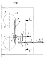
- double molds 3 lying flat are transported at a mutual distance by means of carriers 2.
- the double molds 3 consist of two plate-shaped, superimposed mold halves 4, 5 in which corresponding closed mold cavities are provided. During this transport, the lower mold halves 5 are already filled with pourable mass.
- the double molds 3 are transported in the direction of an arrow 6 to a transfer device 7, which in the manner of a Paternoster lift is trained.
- the transfer device 7 has endless chains 7a, 7b running vertically on both sides of the transport path, which carry support rails 7c-7f for the double molds 3.
- the transfer device has a slide plate 8 which extends practically over the entire height of the vertical transport of the double molds 3 and which can be moved in the direction of the arrow 17 in order to push the double molds off the support rails 7.
- An endless conveyor 13 designed as a chain conveyor has a pair of strands 19 guided over deflection wheel pairs 11, 12, on which support and holding elements 14 for the double molds 3 are hinged about axes 15.
- the support and holding elements 14 enable the double shape not only to pivot about the axis 15, but also about an axis, not shown, lying transversely thereto.
- strands chains
- guide rails 18 are provided which hold the otherwise freely rotatable support and holding elements 14 for the double molds 3 in a rotationally fixed manner.
- a slip clutch is provided between the carrying and holding elements 14 for the two rotary movements.
- the distance between the double molds 3 on the transport path 1 and the transport speed on the transport path 1 on one side and the transport of the double molds 3 through Support rails 7c-7f in the transfer device 7 on the other side and the transport of the double molds 3 in the carrying and holding elements 14 in the vertical section 10 of the endless conveyor 13 on the other side are coordinated with one another in such a way that the individual transfers take place without hindrance and in synchronism can. This means that during the time in which a double mold 3 is transported from the transport path 1 into the area of the transfer device 7, there is no support rail 7c-7f in the transport path.
- the support rails 7c-7d run synchronously and parallel to the support and holding elements 14, so that the individual double molds can be inserted into the adjacent support and holding elements 14 in synchronism by piloting the slide plate 8 in the direction of the arrow 17.
- the distance between the next following double mold 3 in the area of the transfer device 7 is sufficiently long to enable the slide plate 8 to be advanced and moved back.
Landscapes
- Life Sciences & Earth Sciences (AREA)
- Chemical & Material Sciences (AREA)
- Engineering & Computer Science (AREA)
- Food Science & Technology (AREA)
- Polymers & Plastics (AREA)
- Confectionery (AREA)
- Specific Conveyance Elements (AREA)
- Feeding, Discharge, Calcimining, Fusing, And Gas-Generation Devices (AREA)
Description
- Die Erfindung bezieht sich auf eine Transport- und Behandlungsvorrichtung für aus einer oder zwei übereinanderliegenden, Formhohlräume für eine gießfähige, erstarrende Masse, wie Schokoladenmasse, aufweisenden Platten bestehenden Formen, mit einem umlaufenden, insbesondere als Kettenförderer ausgebildeten Endlosförderer, der zur Aufnahme und zum Wenden der Formen Trag- und Halteelemente aufweist.
- Für die Herstellung von Hohlräumen aus gießfähiger, erstarrender Masse, z.B. Schokoladenmasse, werden Formhohlräume aufweisende Doppelformen verwendet, in deren oberer und unterer Platte jeweils einander korrespondierende Formhohlräume ausgebildet sind. Nach dem Einfüllen der gießfähigen Masse in die Formhohlräume der unteren Platte werden durch Auflegen der oberen Platte die Formhohlräume geschlossen.
- Für diese Art der Herstellung der Hohlkörper gibt es verschiedene Vorrichtungen.
- Bei einer bekannten Vorrichtung der eingangs genannten Art sind die Unterformen an den Trag- und Halteelementen des Endlosförderers befestigt, so daß sie in diesem Zustand gefüllt werden können. Das Verschließen mit der Oberform erfolgt durch eine Bedienungsperson, die die Oberform auf die Unterform auflegt und mit Klammern befestigt.
- Bei einer anderen Vorrichtung werden die mit gießfähiger Masse gefüllten Unterformen über eine horizontal verlaufende Transportbahn zu einem Wendezylinder gefördert. Eine Bedienungsperson verschließt die Formen durch Auflegen der Oberform und schiebt die Doppelformen in entsprechende Einschübe des Wendezylinders.
- Bei beiden Vorrichtungen wird eine Bedienungsperson benötigt, die die Doppelformen komplettiert, bevor sie im Kettenförderer oder in der Wendetrommel gewendet werden.
- Die Offenlegungsschrift DE-A-3 112 466 zeigt eine Vorrichtung zum Fördern von Gegenständen, welche von einem unteren Band auf ein oberes Band zugeführt werden sollen. Die zu fördernden Gegenstände sind auch in besagtem Dokument Gießformen mit flüssiger oder noch nicht erstarrter Schokolade. DE-A-3 112 466 beschäftigt sich mit dem Problem, wie vermieden werden kann, daß bei einem Richtungswechsel und Anheben der Gießformen das füssige Schokoladenmaterial die Ränder der Formen überschwemmt. Die hierzu vorgeschlagene Lösung besteht darin, den Transport der Gießformen vom unteren Rand in das obere Band entlang einer kreis- oder sinusförmigen Kurve ablaufen zu lassen, d.h. daß ruckartige Bewegungsoder Richtungsänderungen vermieden werden, so daß ein Überschwappen der Schokolademasse verhindert wird. Ein Zusammenhang mit der, der Erfindung zu Grunde liegenden Übergabe der einzelnen Formen, ohne daß es notwendig ist, daß für diese Aufgabe der Endlosförderer oder die Übergabeeinrichtung angehalten wird, ist der Schrift also nicht zu entnehmen.
- Der Erfindung liegt die Aufgabe zugrunde, eine Transport-und Behandlungsvorrichtung der eingangs genannten Art zu schaffen, bei der die komplettierten Doppelformen automatisch den Trag- und Halteelementen des Endlosförderers zugeführt werden, ohne daß es notwendig ist, daß für diese Übergabe der Endlosförderer angehalten wird.
- Diese Aufgabe wird erfindungsgemäß dadurch gelöst, daß einem vertikal verlaufenden Abschnitt des Endlosförderers eine horizontal verlaufende Transportbahn für die Formen vorgeordnet ist und daß zwischen dem vertikal verlaufenden Abschnitt des Endlosförderers und der Transportbahn eine Übergabevorrichtung angeordnet ist, aus der die von der Transportbahn übernommenen Formen mittels einer Schubvorrichtung unter Gleichlauf an die Trag- und Halteelemente des Endlosförderers überführbar sind.
- Weitere Ausgestaltungen der Erfindung sind in den Unteransprüchen gekennzeichnet. So weist nach einer ersten Ausgestaltung die Übergabevorrichtung Auflageschienen auf, die im vertikal verlaufenden Abschnitt des Endlosförderers parallel und synchron zu den Trag- und Halteelementen des Endlosförderers angetrieben sind. Die wegen der Verteilung der gießfähigen Masse an den Formhohlräumen insbesondere während des Transportes dreh- und/oder schwenkbar am Endlosförderer gelagerten Trag- und Halteelemente werden durch im vertikalen Abschnitt des Endlosförderers vorgesehene Führungsschienen zentriert dreh- und/oder schwenkfest gehalten. Vorzugsweise besteht die Schubvorrichtung aus einer in Transportrichtung der Transportbahn bewegbaren und sich über die vertikale Transporthöhe der Formen in der Übergabevorrichtung erstreckenden Schieber. Die Übergabevorrichtung ist zweckmäßigerweise nach Art eines Paternosteraufzuges ausgebildet.
- Aufgrund der insbesondere nach dem Prinzip eines Paternosteraufzuges ausgebildeten Übergabevorrichtung ergeben sich weder bei der Übernahme der Formen von der Transportbahn durch die Auflageschienen der Übergabevorrichtung noch bei der Übergabe der Formen von den Auflageschienen an die Trag- und Halteelemente des Endlosförderers Schwierigkeiten. Die Veränderung der Transportrichtung der Formen beim Übergang von der Transportbahn auf die Übergabevorrichtung ist deshalb unproblematisch, weil der Abstand der Auflageschienen und damit auch die Zeit, in der sich keine Auflageschienen in der Ebene der Transportbahn befinden, ausreichend groß ist, um die Doppelform in die Position zu überführen, in der sie von den Auflageschienen der Übergabevorrichtung übernommen werden kann. Wegen des großen Abstandes der aufeinanderfolgenden Auflageschienen stört auch nicht der sich über die vertikale Transporthöhe der Dopelformen in der Übergabevorrichtung erstreckende Schieber. Für die Übergabe von den Auflageschienen Übergabevorrichtung an die Trag- und Halteelemente des Endlosförderers steht die gesamte Zeit zur Verfügung, in der die Trag- und Halteelemente parallel zu und synchron mit den Auflageschienen der Übergabevorrichtung laufen.
- Im folgenden wird die Erfindung anhand einer ein Ausführungsbeispiel schematisch darstellenden Zeichnung näher erläutert.
- Im einzelnen zeigen
- Fig. 1
- die Transport- und Behandlungsvorrichtung im Bereich der Übergabevorrichtung mit einem Teil der horizontalen Transportbahn und einem Teil des Endlosförderers in Seitenansicht und
- Fig. 2
- die Transport- und Behandlungsvorrichtung gemäß Fig. 1 im Schnitt nach der Linie I-I der Fig. 1.
- Auf einer Transportbahn 1 werden mittels Mitnehmer 2 flachliegend Doppelformen 3 mit gegenseitigem Abstand transportiert. Die Doppelformen 3 bestehen aus zwei plattenförmigen, übereinanderliegenden Formhälften 4,5, in denen korrespondierende geschlossene Formhohlräume vorgesehen sind. Während dieses Transportes sind die unteren Formhälften 5 bereits mit gießfähiger Masse gefüllt. Die Doppelformen 3 werden in Richtung eines Pfeils 6 zu einer Übergabevorrichtung 7 transportiert, die nach Art eines Paternosteraufzuges ausgebildet ist. Wie Fig. 2 zeigt, weist die Übergabevorrichtung 7 auf beiden Seiten des Transportweges vertikal verlaufende Endlosketten 7a, 7b auf, die Auflageschienen 7c-7f für die Doppelformen 3 tragen. Die Übergabevorrichtung weist eine sich praktisch über die gesamte Höhe des vertikalen Transports der Doppelformen 3 erstreckende Schieberplatte 8 auf, die in Richtung des Pfeils 17 bewegbar ist, um die Doppelformen von den Auflageschienen 7 zu schieben.
- Ein als Kettenförderer ausgebildeter Endlosförderer 13 weist ein Paar über Umlenkräderpaare 11,12 geführte Stränge 19 auf, an denen drehbar um Achsen 15 Trag- und Halteelemente 14 für die Doppelformen 3 angelenkt sind. Die Trag- und Halteelemente 14 ermöglichen der Doppelform nicht nur eine Verschwenkung um die Achse 15, sondern auch um eine dazu querliegende, nicht dargestellte Achse. Mittels nicht dargestellter, zu den Strängen 19 parallel verlaufender Stränge (Ketten) und an den Trag- und Haltelementen 14 vorgesehener, damit gekuppelter Antriebsräder erfolgt die Drehbewegung der Trag- und Halteelemente 15 und damit der Doppelplatten um die beiden erwähnten Achsen, so daß die Doppelformen eine Taumelbewegung während des Transportes ausführen.
- Im Bereich des vertikal verlaufenden Abschnittes 10 des Endlosförderers sind Führungsschienen 18 vorgesehen, die die sonst frei drehbaren Trag- und Halteelemente 14 für die Doppelformen 3 drehfest halten. Damit dies möglich ist, ist zwischen den Trag- und Halteelementen 14 für die beiden Drehbewegungen jeweils eine Rutschkupplung vorgesehen.
- Der Abstand der Doppelformen 3 auf der Transportbahn 1 sowie die Transportgeschwindigkeit auf der Transportbahn 1 auf der einen Seite und der Transport der Doppelformen 3 durch die Auflageschienen 7c-7f in der Übergabevorrichtung 7 auf der anderen Seite und der Transport der Doppelformen 3 in den Trag- und Halteelementen 14 im vertikalen Abschnitt 10 des Endlosförderers 13 auf der weiteren Seite sind derart aufeinander abgestimmt, daß die einzelnen Übergaben behinderungsfrei und im Gleichlauf erfolgen können. Das bedeutet, daß sich während der Zeit, in der eine Doppelform 3 von der Transportbahn 1 in den Bereich der Übergabevorrichtung 7 transportiert wird, sich keine Auflageschiene 7c-7f im Transportweg befindet. Die Auflageschienen 7c-7d laufen synchron und parallel zu den Trag- und Halteelementen 14, so daß im Gleichlauf durch Vorsteuern der Schieberplatte 8 in Richtung des Pfeils 17 die einzelnen Doppelformen in die daneben laufenden Trag-und Halteelemente 14 eingeschoben werden können. Der Abstand der nächstfolgenden Doppelform 3 im Bereich der Übergabevorrichtung 7 ist ausreichend lang, um ein Vorsteuern und Zurückbewegen der Schieberplatte 8 zu ermöglichen.
Claims (5)
- Transport- und Behandlungsvorrichtung für aus einer oder zwei übereinanderliegenden, Formhohlräume für eine gießfähige, erstarrende Masse, wie Schokoladenmasse, aufweisenden Platten bestehenden Formen, mit einem umlaufenden, insbesondere als Kettenförderer ausgebildeten Endlosförderer, der zur Aufnahme und zum Wenden der Formen Trag- und Haltelemente aufweist,
dadurch gekennzeichnet, daß einem vertikal verlaufenden Abschnitt (10) des Endlosförderers (13) eine horizontal verlaufende Transportbahn (1) für die Formen (3) vorgeordnet ist und daß zwischen dem vertikal verlaufenden Abschnitt (10) des Endlosförderers (13) und der Transportbahn (1) eine Übergabevorrichtung (7) angeordnet ist, aus der die von der Transportbahn (1) übernommenen Formen (3) mittels einer Schubvorrichtung (8) unter Gleichlauf parallel und synchron an die Tragund Halteelemente (14) des Endlosförderers (13) überführbar sind, ohne daß es notwendig ist, daß für diese Aufgabe der Endlosförderer angehalten wird. - Transport- und Behandlungsvorrichtung nach Anspruch 1,
dadurch gekennzeichnet, daß die Übergabevorrichtung (7) Auflageschienen (7c-7f) aufweist, die in dem vertikal verlaufenden Abschnitt (10) des Endlosförderers parallel und synchron zu den Trag- und Haltelementen (14) des Endlosförderers (13) angetrieben sind. - Transport- und Behandlungsvorrichtung nach Anspruch 1 oder 2,
dadurch gekennzeichnet, daß die dreh- und/oder schwenkbar am Endlosförderer (13) gelagerten Trag- und Halteelemente (14) durch im vertikalen Abschnitt (10) des Endlosförderers (13) vorgesehene Führungsschienen (18) dreh- und/oder schwenkfest gehalten sind. - Transport- und Behandlungsvorrichtung nach einem der Ansprüche 1 bis 3,
dadurch gekennzeichnet, daß die Schubvorrichtung (8) aus einem in Transportrichtung (6) der Transportbahn bewegbaren und sich über die vertikale Transporthöhe der Formen (3) in der Übergabevorrichtung (7) erstreckenden Schieber besteht. - Transport- und Behandlungsvorrichtung nach einem der Ansprüche 1 bis 4,
dadurch gekennzeichnet, daß die Übergabevorrichtung (7) nach Art eines Paternosteraufzuges ausgebildet ist.
Priority Applications (1)
| Application Number | Priority Date | Filing Date | Title |
|---|---|---|---|
| AT88100296T ATE70405T1 (de) | 1987-02-16 | 1988-01-12 | Transport- und behandlungsvorrichtung fuer mit giessfaehiger, erstarrender masse, wie schokolade, fuellbare formen. |
Applications Claiming Priority (2)
| Application Number | Priority Date | Filing Date | Title |
|---|---|---|---|
| DE3704761 | 1987-02-16 | ||
| DE3704761 | 1987-02-16 |
Publications (3)
| Publication Number | Publication Date |
|---|---|
| EP0286778A2 EP0286778A2 (de) | 1988-10-19 |
| EP0286778A3 EP0286778A3 (en) | 1988-12-21 |
| EP0286778B1 true EP0286778B1 (de) | 1991-12-18 |
Family
ID=6321040
Family Applications (1)
| Application Number | Title | Priority Date | Filing Date |
|---|---|---|---|
| EP88100296A Expired - Lifetime EP0286778B1 (de) | 1987-02-16 | 1988-01-12 | Transport- und Behandlungsvorrichtung für mit giessfähiger, erstarrender Masse, wie Schokolade, füllbare Formen |
Country Status (6)
| Country | Link |
|---|---|
| US (1) | US4822268A (de) |
| EP (1) | EP0286778B1 (de) |
| AT (1) | ATE70405T1 (de) |
| AU (1) | AU1172588A (de) |
| DE (1) | DE3866924D1 (de) |
| ES (1) | ES2028138T3 (de) |
Families Citing this family (4)
| Publication number | Priority date | Publication date | Assignee | Title |
|---|---|---|---|---|
| IT1264299B1 (it) * | 1993-12-23 | 1996-09-23 | Prb Packaging Systems Srl | Dispositivo per l'estrazione in continuo di articoli da una linea principale a uscite intermedie poste angolarmente rispetto a tale |
| DE19758169A1 (de) | 1997-12-30 | 1999-07-08 | Bindler Maschf Gebr Gmbh Co Kg | Vorrichtung zur Herstellung von Schokoladenhülsen |
| WO2007065219A1 (en) * | 2005-12-09 | 2007-06-14 | Idee Products Pty Ltd | Spin moulding apparatus |
| ITTO20080263A1 (it) * | 2008-04-04 | 2009-10-05 | Tecnosweet S R L | Impianto di trasporto per linee di modellazione di prodotti dolciari, particolarmente di cioccolato |
Family Cites Families (17)
| Publication number | Priority date | Publication date | Assignee | Title |
|---|---|---|---|---|
| DE7136858U (de) * | 1971-12-23 | Salmet Gmbh & Co Kg | Vorrichtung zur Übergabe von Eiern von einem Querförderband auf einen Senkrechtförderer in einer Eiertransportvorrichtung | |
| US880300A (en) * | 1904-10-10 | 1908-02-25 | Peregrine Oliver Wilson | Manufacture of sweetmeat, such as chocolate. |
| US1118619A (en) * | 1910-01-28 | 1914-11-24 | George Samuel Baker | Chocolate-depositing machine. |
| US1169602A (en) * | 1915-04-17 | 1916-01-25 | Alonzo Linton Bausman | Machine for automatically molding confectionery. |
| US1475579A (en) * | 1922-01-19 | 1923-11-27 | Milton J Harlan | Device for forming chocolates |
| US3347351A (en) * | 1964-06-03 | 1967-10-17 | Internat Machinery Corp | Hydrostatic cooker bars |
| US3318263A (en) * | 1964-12-07 | 1967-05-09 | Baker Perkins Ltd | Manufacture of confectionery |
| DE1272695B (de) * | 1965-07-30 | 1968-07-11 | Kurt Duennebier | Maschine zum Giessen von Suesswaren in Formen mit Puderfuellung |
| GB1302792A (de) * | 1969-05-09 | 1973-01-10 | ||
| US3801255A (en) * | 1970-12-22 | 1974-04-02 | Ms Eng Inc | Automatic casting machine |
| US3798337A (en) * | 1971-07-22 | 1974-03-19 | Noel Y Co Ltd Sa Argentina De | Process for the continuous manufacture of foamed sweets |
| JPS502033B2 (de) * | 1971-09-11 | 1975-01-23 | ||
| US3927976A (en) * | 1973-09-26 | 1975-12-23 | Fmc Corp | Containerized hydrostatic sterilizing system |
| US3976208A (en) * | 1975-02-03 | 1976-08-24 | The Quaker Oats Company | Apparatus for providing endless succession of compartmented trays |
| DE2855982A1 (de) * | 1978-12-23 | 1980-07-10 | Rosenkaimer Gmbh Siemag | Stueckgut-transportvorrichtung |
| US4436500A (en) * | 1980-01-07 | 1984-03-13 | Wheaton Industries | In-line rotational casting apparatus |
| DE3112466A1 (de) * | 1981-03-28 | 1982-10-21 | Schoma-Schokoladenmaschinenbau GmbH, 5275 Bergneustadt | "vorrichtung zum anheben oder absenken von giessformen, insbesondere von giessformen mit artikeln aus fluessiger oder noch nicht vollstaendig erstarrter schokolade" |
-
1988
- 1988-01-12 EP EP88100296A patent/EP0286778B1/de not_active Expired - Lifetime
- 1988-01-12 DE DE8888100296T patent/DE3866924D1/de not_active Expired - Fee Related
- 1988-01-12 ES ES198888100296T patent/ES2028138T3/es not_active Expired - Lifetime
- 1988-01-12 AT AT88100296T patent/ATE70405T1/de not_active IP Right Cessation
- 1988-02-12 US US07/155,190 patent/US4822268A/en not_active Expired - Fee Related
- 1988-02-15 AU AU11725/88A patent/AU1172588A/en not_active Abandoned
Also Published As
| Publication number | Publication date |
|---|---|
| ES2028138T3 (es) | 1992-07-01 |
| AU1172588A (en) | 1988-08-18 |
| EP0286778A3 (en) | 1988-12-21 |
| DE3866924D1 (de) | 1992-01-30 |
| US4822268A (en) | 1989-04-18 |
| EP0286778A2 (de) | 1988-10-19 |
| ATE70405T1 (de) | 1992-01-15 |
Similar Documents
| Publication | Publication Date | Title |
|---|---|---|
| DE3107584C2 (de) | ||
| EP1767474A2 (de) | Vorrichtung zum Handhaben von Gegenständen, wie Kartons | |
| DE3740109C2 (de) | ||
| DE2159714C3 (de) | Vorrichtung zum Trennen von durch horizontale Schnitte abgegrenzten, nach dem Härten zu einem Stapel zusammenhaftenden Gasbetonelementen | |
| DE2921388A1 (de) | Foerdervorrichtung | |
| EP1343379B1 (de) | Backofen zur herstellung von gebackenen formkörpern | |
| DE3105520A1 (de) | Verfahren und vorrichtung zur handhabung von scheibenmaterial, insbesondere von windschutzscheiben fuer kraftwagen | |
| DE102018002280A1 (de) | Endlos umlaufende Behälter-Fördervorrichtung in einer Verpackungsmaschine | |
| EP0286778B1 (de) | Transport- und Behandlungsvorrichtung für mit giessfähiger, erstarrender Masse, wie Schokolade, füllbare Formen | |
| DE2432579A1 (de) | Vorrichtung zum stapeln von buechern oder dgl. | |
| DE2246190B2 (de) | Flurförderzeug zum Auswechseln von Modellplattenpaare einer Gießerei-Formanlage | |
| DE2822916C2 (de) | Vorrichtung zur Beförderung von geteilten Gießformen | |
| DE2051525A1 (en) | Foam mould opening mechanism - comprises upper and lower rail tracks defining vertical spacing of half moulds | |
| DE580493C (de) | Fortlaufend angetriebener endloser biegsamer Foerderer | |
| DE1810796B2 (de) | Vorrichtung zum Umsetzen von Formen fuer keramische Formlinge zwischen zwei Foerderern | |
| DE1151457B (de) | Vorrichtung zum Drehen von keramischen Formlingen od. dgl. Formkoerpern | |
| DE2408158A1 (de) | Vorrichtung zum gleichzeitigen absondern und umsetzen von gegenstaenden | |
| DE2264160C3 (de) | Vorrichtung zum Verteilen von sich in einer Reihe bewegenden Gegenständen auf eine Mehrzahl getrennter Bahnen | |
| DE1604745C3 (de) | Vorrichtung zur Herstellung von Back- oder Genusswaren aus einer dickflüssigen Masse | |
| DE930196C (de) | Niveaugleiche Rollenbahnkreuzung | |
| DE4439288C2 (de) | Verfahren und Vorrichtung zur Zuführung frischer Ziegelformlinge zu einer Greifstation für die Formlingsträger-Beladung | |
| DE19525436C2 (de) | Beschickung eines wenigstens in einem Abschnitt permanent laufenden Fördermittels | |
| DE1556567C (de) | Becherförderer | |
| DE2239598C3 (de) | Vorrichtung für das Aufbringen von Teigstücken auf einen Endlosförderer einer Garzelle, eines Backofens oder dergleichen | |
| AT232420B (de) | Vorrichtung zum Drehen von Formkörpern |
Legal Events
| Date | Code | Title | Description |
|---|---|---|---|
| PUAI | Public reference made under article 153(3) epc to a published international application that has entered the european phase |
Free format text: ORIGINAL CODE: 0009012 |
|
| AK | Designated contracting states |
Kind code of ref document: A2 Designated state(s): AT BE CH DE ES FR GB GR IT LI LU NL SE |
|
| PUAL | Search report despatched |
Free format text: ORIGINAL CODE: 0009013 |
|
| AK | Designated contracting states |
Kind code of ref document: A3 Designated state(s): AT BE CH DE ES FR GB GR IT LI LU NL SE |
|
| 17P | Request for examination filed |
Effective date: 19890113 |
|
| 17Q | First examination report despatched |
Effective date: 19900626 |
|
| GRAA | (expected) grant |
Free format text: ORIGINAL CODE: 0009210 |
|
| AK | Designated contracting states |
Kind code of ref document: B1 Designated state(s): AT BE CH DE ES FR GB GR IT LI LU NL SE |
|
| PG25 | Lapsed in a contracting state [announced via postgrant information from national office to epo] |
Ref country code: SE Effective date: 19911218 Ref country code: GR Free format text: LAPSE BECAUSE OF FAILURE TO SUBMIT A TRANSLATION OF THE DESCRIPTION OR TO PAY THE FEE WITHIN THE PRESCRIBED TIME-LIMIT Effective date: 19911218 |
|
| REF | Corresponds to: |
Ref document number: 70405 Country of ref document: AT Date of ref document: 19920115 Kind code of ref document: T |
|
| ET | Fr: translation filed | ||
| GBT | Gb: translation of ep patent filed (gb section 77(6)(a)/1977) | ||
| REF | Corresponds to: |
Ref document number: 3866924 Country of ref document: DE Date of ref document: 19920130 |
|
| PG25 | Lapsed in a contracting state [announced via postgrant information from national office to epo] |
Ref country code: LU Free format text: LAPSE BECAUSE OF NON-PAYMENT OF DUE FEES Effective date: 19920131 |
|
| ITF | It: translation for a ep patent filed |
Owner name: STUDIO JAUMANN |
|
| REG | Reference to a national code |
Ref country code: ES Ref legal event code: FG2A Ref document number: 2028138 Country of ref document: ES Kind code of ref document: T3 |
|
| PLBE | No opposition filed within time limit |
Free format text: ORIGINAL CODE: 0009261 |
|
| STAA | Information on the status of an ep patent application or granted ep patent |
Free format text: STATUS: NO OPPOSITION FILED WITHIN TIME LIMIT |
|
| 26N | No opposition filed | ||
| PGFP | Annual fee paid to national office [announced via postgrant information from national office to epo] |
Ref country code: ES Payment date: 19930129 Year of fee payment: 6 |
|
| PGFP | Annual fee paid to national office [announced via postgrant information from national office to epo] |
Ref country code: NL Payment date: 19930131 Year of fee payment: 6 |
|
| PG25 | Lapsed in a contracting state [announced via postgrant information from national office to epo] |
Ref country code: ES Free format text: LAPSE BECAUSE OF NON-PAYMENT OF DUE FEES Effective date: 19940113 |
|
| PG25 | Lapsed in a contracting state [announced via postgrant information from national office to epo] |
Ref country code: NL Effective date: 19940801 |
|
| NLV4 | Nl: lapsed or anulled due to non-payment of the annual fee | ||
| PGFP | Annual fee paid to national office [announced via postgrant information from national office to epo] |
Ref country code: FR Payment date: 19951221 Year of fee payment: 9 |
|
| PGFP | Annual fee paid to national office [announced via postgrant information from national office to epo] |
Ref country code: GB Payment date: 19951228 Year of fee payment: 9 |
|
| PGFP | Annual fee paid to national office [announced via postgrant information from national office to epo] |
Ref country code: AT Payment date: 19960103 Year of fee payment: 9 |
|
| PGFP | Annual fee paid to national office [announced via postgrant information from national office to epo] |
Ref country code: BE Payment date: 19960117 Year of fee payment: 9 |
|
| PGFP | Annual fee paid to national office [announced via postgrant information from national office to epo] |
Ref country code: CH Payment date: 19960123 Year of fee payment: 9 |
|
| PGFP | Annual fee paid to national office [announced via postgrant information from national office to epo] |
Ref country code: DE Payment date: 19960301 Year of fee payment: 9 |
|
| PG25 | Lapsed in a contracting state [announced via postgrant information from national office to epo] |
Ref country code: GB Effective date: 19970112 Ref country code: AT Effective date: 19970112 |
|
| PG25 | Lapsed in a contracting state [announced via postgrant information from national office to epo] |
Ref country code: LI Effective date: 19970131 Ref country code: CH Effective date: 19970131 Ref country code: BE Effective date: 19970131 |
|
| BERE | Be: lapsed |
Owner name: GEBR. BINDLER MASCHINENFABRIK G.M.B.H. & CO. K.G. Effective date: 19970131 |
|
| GBPC | Gb: european patent ceased through non-payment of renewal fee |
Effective date: 19970112 |
|
| REG | Reference to a national code |
Ref country code: CH Ref legal event code: PL |
|
| PG25 | Lapsed in a contracting state [announced via postgrant information from national office to epo] |
Ref country code: FR Effective date: 19970930 |
|
| PG25 | Lapsed in a contracting state [announced via postgrant information from national office to epo] |
Ref country code: DE Effective date: 19971101 |
|
| REG | Reference to a national code |
Ref country code: FR Ref legal event code: ST |
|
| REG | Reference to a national code |
Ref country code: ES Ref legal event code: FD2A Effective date: 19990301 |
|
| PG25 | Lapsed in a contracting state [announced via postgrant information from national office to epo] |
Ref country code: IT Free format text: LAPSE BECAUSE OF NON-PAYMENT OF DUE FEES;WARNING: LAPSES OF ITALIAN PATENTS WITH EFFECTIVE DATE BEFORE 2007 MAY HAVE OCCURRED AT ANY TIME BEFORE 2007. THE CORRECT EFFECTIVE DATE MAY BE DIFFERENT FROM THE ONE RECORDED. Effective date: 20050112 |