EP0285925A2 - Dichtungsprofil - Google Patents
Dichtungsprofil Download PDFInfo
- Publication number
- EP0285925A2 EP0285925A2 EP88104789A EP88104789A EP0285925A2 EP 0285925 A2 EP0285925 A2 EP 0285925A2 EP 88104789 A EP88104789 A EP 88104789A EP 88104789 A EP88104789 A EP 88104789A EP 0285925 A2 EP0285925 A2 EP 0285925A2
- Authority
- EP
- European Patent Office
- Prior art keywords
- spring steel
- sealing
- sealing profile
- profile according
- sealing lip
- Prior art date
- Legal status (The legal status is an assumption and is not a legal conclusion. Google has not performed a legal analysis and makes no representation as to the accuracy of the status listed.)
- Granted
Links
Images


Classifications
-
- B—PERFORMING OPERATIONS; TRANSPORTING
- B60—VEHICLES IN GENERAL
- B60J—WINDOWS, WINDSCREENS, NON-FIXED ROOFS, DOORS, OR SIMILAR DEVICES FOR VEHICLES; REMOVABLE EXTERNAL PROTECTIVE COVERINGS SPECIALLY ADAPTED FOR VEHICLES
- B60J10/00—Sealing arrangements
- B60J10/70—Sealing arrangements specially adapted for windows or windscreens
- B60J10/74—Sealing arrangements specially adapted for windows or windscreens for sliding window panes, e.g. sash guides
- B60J10/79—Sealing arrangements specially adapted for windows or windscreens for sliding window panes, e.g. sash guides for flush-glass windows, i.e. for windows flush with the vehicle body or the window frame
-
- B—PERFORMING OPERATIONS; TRANSPORTING
- B60—VEHICLES IN GENERAL
- B60J—WINDOWS, WINDSCREENS, NON-FIXED ROOFS, DOORS, OR SIMILAR DEVICES FOR VEHICLES; REMOVABLE EXTERNAL PROTECTIVE COVERINGS SPECIALLY ADAPTED FOR VEHICLES
- B60J10/00—Sealing arrangements
- B60J10/15—Sealing arrangements characterised by the material
- B60J10/16—Sealing arrangements characterised by the material consisting of two or more plastic materials having different physical or chemical properties
-
- B—PERFORMING OPERATIONS; TRANSPORTING
- B60—VEHICLES IN GENERAL
- B60J—WINDOWS, WINDSCREENS, NON-FIXED ROOFS, DOORS, OR SIMILAR DEVICES FOR VEHICLES; REMOVABLE EXTERNAL PROTECTIVE COVERINGS SPECIALLY ADAPTED FOR VEHICLES
- B60J10/00—Sealing arrangements
- B60J10/15—Sealing arrangements characterised by the material
- B60J10/18—Sealing arrangements characterised by the material provided with reinforcements or inserts
-
- B—PERFORMING OPERATIONS; TRANSPORTING
- B60—VEHICLES IN GENERAL
- B60J—WINDOWS, WINDSCREENS, NON-FIXED ROOFS, DOORS, OR SIMILAR DEVICES FOR VEHICLES; REMOVABLE EXTERNAL PROTECTIVE COVERINGS SPECIALLY ADAPTED FOR VEHICLES
- B60J10/00—Sealing arrangements
- B60J10/20—Sealing arrangements characterised by the shape
- B60J10/24—Sealing arrangements characterised by the shape having tubular parts
-
- B—PERFORMING OPERATIONS; TRANSPORTING
- B60—VEHICLES IN GENERAL
- B60J—WINDOWS, WINDSCREENS, NON-FIXED ROOFS, DOORS, OR SIMILAR DEVICES FOR VEHICLES; REMOVABLE EXTERNAL PROTECTIVE COVERINGS SPECIALLY ADAPTED FOR VEHICLES
- B60J10/00—Sealing arrangements
- B60J10/20—Sealing arrangements characterised by the shape
- B60J10/26—Sealing arrangements characterised by the shape characterised by the surface shape
- B60J10/265—Sealing arrangements characterised by the shape characterised by the surface shape the surface being primarily decorative
-
- B—PERFORMING OPERATIONS; TRANSPORTING
- B60—VEHICLES IN GENERAL
- B60J—WINDOWS, WINDSCREENS, NON-FIXED ROOFS, DOORS, OR SIMILAR DEVICES FOR VEHICLES; REMOVABLE EXTERNAL PROTECTIVE COVERINGS SPECIALLY ADAPTED FOR VEHICLES
- B60J10/00—Sealing arrangements
- B60J10/30—Sealing arrangements characterised by the fastening means
-
- B—PERFORMING OPERATIONS; TRANSPORTING
- B60—VEHICLES IN GENERAL
- B60J—WINDOWS, WINDSCREENS, NON-FIXED ROOFS, DOORS, OR SIMILAR DEVICES FOR VEHICLES; REMOVABLE EXTERNAL PROTECTIVE COVERINGS SPECIALLY ADAPTED FOR VEHICLES
- B60J10/00—Sealing arrangements
- B60J10/70—Sealing arrangements specially adapted for windows or windscreens
- B60J10/74—Sealing arrangements specially adapted for windows or windscreens for sliding window panes, e.g. sash guides
- B60J10/75—Sealing arrangements specially adapted for windows or windscreens for sliding window panes, e.g. sash guides for sealing the lower part of the panes
Definitions
- the invention relates to a sealing profile made of elastomeric material or plastic with at least one protruding sealing lip that can be elastically applied to the counter surface to be sealed.
- sealing profiles are known for example from DE-PS 29 45 836 and DE-OS 30 16 263.
- the protruding sealing lips are either made of a rubber of lower Shore hardness or the holding area is provided with additional reinforcement in order to create areas of different hardness.
- Such sealing lips made of elastomeric material or plastic generally have a permanent deformation and have only a relatively low return speed, even if they are provided with a conventional reinforcement. This results in difficulties in sealing on motor vehicles, particularly at high speeds, since the side window frames can be removed from their normal position by up to several millimeters due to the suction force of the driving wind, the gap which occurs does not immediately close again. The sealing lips only come into contact again when the speed drops and the pane frames return to their original position.
- the present invention is therefore based on the object Reasons to create a sealing profile that has a high return speed and thus always ensures a secure seal of the corresponding counter surface.
- the sealing profile has at least one reinforcement made from a highly elastic, band-shaped spring steel and extending into the sealing lip.
- This spring steel strip insert ensures that there is always a constant contact pressure and that, in particular, a reset takes place practically without delay.
- the contact pressure and the elasticity can be partially changed and adjusted over the width of the band, in that the spring steel band has punched-outs which extend across the width across the longitudinal direction.
- the punched-out areas can have an increasing width towards a longitudinal edge of the spring steel strip.
- the punched-out areas can extend to at least one of the two longitudinal edges of the spring steel strip and be open there.
- a further series of punchings can also be provided to improve the anchoring in the covering material.
- the profile with the sealing lip itself can be made from one uniform material. However, it is also possible for the profile with the sealing lip to have at least two cross-sectional areas with material of different hardness, in which case the spring steel reinforcement then extends over both areas of different hardness.
- Both reinforcements can run parallel to one another over a partial area and can be spaced apart in this area by a layer of profile material.
- the reinforcement consists of a flat, elongated band 1 made of tough spring steel of relatively small thickness - for example less than 0.1 mm - into which two rows of punched-outs 2 and 3 are cut side by side.
- the punched holes 2 are trapezoidal, the longer parallel side 4 running adjacent to a side edge 5 of the spring steel strip 1, while the punched holes 3 consist of rectangles.
- the punched holes 2 of any geometrical design serve to adjust the elasticity and the restoring force of the spring steel band, while the punched holes 3 are essentially provided to enable better anchoring in the cover material or passage of the profile material.
- the punched 2 extend from its narrow side of slots 6 to the edge 7 of the spring steel strip 1 and are thus open to the side.
- FIG. 3 A first application example of such a spring steel insert is shown in FIG. 3 with the aid of a cross section th sill seal 10 shown.
- This sill seal 10 consists of an approximately V-shaped rubber profile 11 of uniform material in cross section, in which a spring steel strip 1 is embedded as reinforcement.
- the rectangular cutouts 3 according to FIG. 1 lie in the vertical region of the sill seal 10, which can then be fixed to the body, for example, by means of an adhesive layer 12 or a double-sided adhesive tape.
- the trapezoidal cut-outs 2 of the spring steel strip 1 lie in the laterally protruding sealing lip 13 and, through appropriate configuration of the cut-outs 2 with approximately constant sealing lip cross-section, result in a different elasticity and restoring force of the individual sealing lip sections corresponding to the desired requirements, so that a secure contact with and sealing of the the drawing, the counter surface not shown is guaranteed.
- a clamping profile 20 which consists of a U-shaped terminal block 21 made of harder material and a protruding from the end of a free leg of the terminal block 21 sealing lip 22 made of softer material, which seals against a washer 23.
- the terminal block 21 is pushed onto a flange 24 of the door panel.
- a reinforcement in the form of a spring steel strip 1 extends both over the terminal strip 21 and over the sealing lip 22, which can also be provided in the sealing lip area 22 with corresponding punched-out areas for adjusting the elasticity.
- This spring steel band 1 which extends over both material areas, once reinforces the clamping strip 21, which is made of harder material, while a high elasticity and a high restoring force is ensured in the softer area of the sealing lip 22.
- the sealing lip 22 on its outside side still be provided with a sliding layer 25 or flocking.
- a U-shaped clamping profile 31 is shown with a laterally projecting sealing lip 32, wherein the profile is also made of a uniform material.
- the clamping profile 31 has a separate conventional reinforcement 33 made of an aluminum or steel stamped strip, while a spring steel strip 1 runs in the sealing lip 32, the inner end of which extends parallel to one leg of the stamped strip 33.
- the spring steel strip 1 has corresponding punchings 2 in the area of the sealing lip 32. It is essential that the inner leg 34 of the spring steel band and the leg 35 of the punched band 33 are at least slightly spaced from one another, so that the profile material can flow well between the two legs 34 and 35.
- FIG. 6 shows a cross section through a shaft seal 40 for the pane 41 of a motor vehicle.
- a U-shaped clamping profile 43 with a metal reinforcement 44 is placed on the upper edge of the door panel 42, from which a sealing lip 45 projects laterally toward the pane 41.
- a slightly angled spring steel strip 1 with rubber-metal adhesion is extruded into this sealing lip 45, the region of the spring steel strip 1 extending in the sealing lip 45 likewise having punchings corresponding to FIG. 1 or can also be made of full material.
- the width range of the spring steel strip 1 lying in the clamping profile 43 runs there parallel to the metal reinforcement 44.
- On the side of the sealing lip 45 facing the disk 41 there is also a sliding layer 46 in the form of a Flocking or a PU lubricating varnish applied.
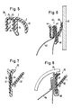
- FIG. 7 Another design of a shaft seal 50 is shown in FIG. 7.
- the vertically lying profile web 51 has a sealing lip 52 which projects laterally from approximately half the height, both parts being made of a material of uniform hardness.
- a conventional reinforcement 53 is embedded in the vertical profile web 51, while the sealing lip 52 has a spring steel strip 1 which is angled in a V-shape at the inner end and runs parallel to the reinforcement 53 there.
- the spring steel strip 1 can have a corresponding offset 54 in the area running parallel to the reinforcement 53, so that the space between the spring steel strip 1 and the reinforcement 53 is also well filled with profile material.
- a shaft seal corresponding to FIG. 7 is shown, but in which the vertical profile web 61 is made of a harder material than the sealing lip 62.
- a reinforcement in the form of a V-shape is in the illustrated embodiment bent spring steel strip 1 extruded, one leg extending inside the sealing lip 62 and the other leg extending upward in the profile web 61.
- This shaft seal is fixed by means of a metal bracket 63, which is placed on the door flange 64 and an inner cladding 65 which holds up from above.
- a sealing profile 70 for sealing the gap between the pane 71 and the lower roof edge 72 is shown.
- the sealing profile 70 has an area 73 made of hard rubber or hard PVC, to which the actual sealing areas 74 made of soft rubber or soft PVC for the upper edge of the pane 71 are extruded.
- a V-shaped sealing lip 75 with a spring steel strip insert 1 is extruded on the upper side with one leg, the sealing lip 75 and spring steel strip insert 1 being arranged approximately in the form of a lying V.
- the illustrated embodiment shows the state when the door is closed, i.e.
- a sealing profile 80 for sealing the gap between a pane 81 and the lower roof edge 82 is also shown.
- the sealing profile 80 has on the outside a weakly V-shaped, bent sealing lip 83 with a correspondingly shaped spring steel strip insert 1, one leg 84 of the sealing lip 83 abutting the outside of the pane 81 and the other leg 85 pressed against the front edge of the roof underside 82.
- the effect of the Spring steel band insert 1 always ensures a secure seal and contact of the sealing lips 84 and 85.
Landscapes
- Engineering & Computer Science (AREA)
- Mechanical Engineering (AREA)
- Seal Device For Vehicle (AREA)
- Gasket Seals (AREA)
- Specific Sealing Or Ventilating Devices For Doors And Windows (AREA)
Abstract
Description
- Die Erfindung bezieht sich auf ein Dichtungsprofil aus elastomerem Material oder Kunststoff mit mindestens einer abragenden, sich an der abzudichtenden Gegenfläche elastisch anlegbaren Dichtlippe.
- Derartige Dichtungsprofile sind beispeilsweise aus der DE-PS 29 45 836 und aus der DE-OS 30 16 263 bekannt. Dabei sind die abragenden Dichtlippen entweder aus einem Gummi geringerer Shorehärte gefertig oder der Haltebereich ist mit einer zusätzlichen Armierung versehen, um damit auch Bereiche unterschiedlicher Härte zu schaffen. Derartige Dichtlippen aus elastomerem Material oder Kunststoff weisen im allgemeinen eine bleibende Verformung auf und haben nur eine relativ geringe Rückstellgeschwindigkeit, auch wenn sie mit einer herkömmlichen Armierung versehen sind. Dadurch ergeben sich Schwierigkeiten bei der Abdichtung an Kraftfahrzeugen, insbesondere bei hohen Geschwindigkeiten, da sich durch die Sogwirkung des Fahrtwindes die Seitenscheibenrahmen bis zu mehreren Millimetern aus ihrer Normallage entfernen können, wobei sich der dabei auftretende Spalt nicht sofort wieder verschließt. Erst bei einem Absinken der Geschwindigkeit und Zurückkehren der Scheibenrahmen in ihre Ursprungslage kommen die Dichtlippen wieder zur Anlage.
- Der vorliegenden Erfindung liegt daher die Aufgabe zu grunde, eine Dichtungsprofil zu schaffen, das eine hohe Rückstellgeschwindigkeit aufweist und damit stets eine sichere Abdichtung der entsprechenden Gegenfläche gewährleistet.
- Zur Lösung dieser Aufgabe ist erfindungsgemäß vorgesehen, daß das Dichtungsprofil mindestens eine, sich bis in die Dichtlippe erstreckende Armierung aus einem hochelastischen, bandförmigen Federstahl aufweist.
- Durch diese Federstahlbandeinlage ist sicher gewährleistet, daß stets ein gleichmäßiger Anpreßdruck vorhanden ist und daß insbesondere eine Rückstellung praktisch ohne Verzögerung erfolgt.
- Der Anpreßdruck und die Elastizität kann dabei über die Breite des Bandes gesehen partiell geändert und eingestellt werden, indem das Federstahlband sich quer zur Längsrichtung über die Breite erstreckende Ausstanzungen aufweist.
- Die Ausstanzungen können dabei zu einer Längskante des Federstahlbandes hin zunehmende Breite aufweisen.
- Damit das Dichtungsprofil auch in der Ebene der Armierung flexibel ist, können die Ausstanzungen bis zu wenigstens einer der beiden Längskanten des Federstahlbandes verlaufen und dort offen sein.
- Neben den die Höhe des Anpreßdruckes bestimmenden Ausstanzungen kann auch eine weitere Reihe von Ausstanzungen zur Verbesserung der Verankerung im Deckmaterial vorgesehen sein.
- Das Profil mit der Dichtlippe selbst kann aus einem ein heitlichen Material bestehen. Es ist aber auch möglich, daß das Profil mit der Dichtlippe mindestens zwei Querschnittsbereiche mit Material unterschiedlicher Härte aufweist, wobei sich dann die Federstahlarmierung über beide Bereiche unterschiedlicher Härte erstreckt.
- Zusätzlich zur Federstahlarmierung kann noch eine weitere Armierung in Form eines herkömmlichen Stanzbandes vorgesehen sein.
- Dabei können beide Armierungen über einen Teilbereich parallel zueinander verlaufen und in diesem Bereich durch eine Schicht Profilmaterial beabstandet sein.
- Anhand einer schematischen Zeichnung sind Aufbau und Wirkungsweise von Ausführungsbeispielen nach der Erfindung näher erläutert.
- Dabei zeigen
- Fig. 1 eine Aufsicht durch ein flaches Federstahlband,
- Fig. 2 eine Aufsicht auf eine andere Ausgestaltung des Federstahlbandes,
- Fig. 3 die Ausbildung einer Schwellerdichtung mit einem solchen Federstahlband,
- Fig. 4 ein U-förmiges Dichtprofil mit seitlich abragender Dichtlippe aus zwei verschiedenen Materialien,
- Fig. 5 ein U-förmiges Klemmprofil mit seitlich abragender Dichtlippe aus einheitlichem Material, aber einer zusätzlichen Armierung,
- Fig. 6 eine Schachtabdichtung aus einheitlichem Material mit zwei verschiedenen Armierungen,
- Fig. 7 eine weitere Gestaltung einer Schachtabdichtung aus einheitlichem Material mit zwei verschiedenen Armierungen,
- Fig. 8 eine Schachtabdichtung aus unterschiedlichem Material, jedoch nur mit einer Federstahlarmierung,
- Fig. 9 einen Querschnitt durch ein Fensterführungsprofil mit Dichtlippe im Spalt zur Dachunterkante und
- Fig. 10 einen Querschnitt durch eine weitere Abdichtung zwischen Scheibenoberkante und Dachunterkante.
- Wie man aus Fig. 1 ersieht, besteht die Armierung aus einem flachen, lang gestreckten Band 1 aus zähem Federstahl relativ geringer Dicke - beispielsweise von weniger als 0,1 mm - in das nebeneinanderliegend zwei Reihen von Ausstanzungen 2 und 3 eingeschnitten sind. Bei dem dargestellten Ausführungsbeispiel sind die Ausstanzungen 2 trapezförmig ausgebildet, wobei die längere Parallelseite 4 angrenzend an eine Seitenkante 5 des Federstahlbandes 1 verläuft, während die Ausstanzungen 3 aus Rechtecken bestehen.
- Bei einer derartigen Gestaltung der Ausstanzungen 2 ergibt sich, daß der stehenbleibende Materialquerschnitt des Federstahlbandes 1 zum linken Rand 5 hin abnimmt, so daß dadurch ein weicheres, elastisches Verhalten und eine Variation des Anpreßdruckes und der Rückstellkraft des Federstahlbandes zum Rand hin erhalten wird.
- Damit können je nach Wahl, ob ein massives Federstahlband ohne Ausstanzungen oder ein solches mit Ausstanzungen verwendet wird, unterschiedliche Rückstellkräfte eingestellt und entsprechend der jeweiligen Größe und/oder Geometrie der Ausstanzungen abschnittsweise über die Breite des Federstahlbandes ein unterschiedliches Elastizitätsverhalten erreicht werden in dem Sinne, daß das Federstahlband beispielsweise zum Rand hin starrer oder flexibler wird.
- Die Ausstanzungen 2 beliebiger geometrischer Gestaltung dienen dabei zur Einstellung der Elastizität und der Rückstellkraft des Federstahlbandes, während die Ausstanzungen 3 im wesentlichen vorgesehen sind, um eine bessere Verankerung im Deckmaterial bzw. einen Durchtritt des Profilmaterials zu ermöglichen.
- Um darüber hinaus sicherzustellen, daß das Federstahlband auch dreidimensional, d.h. um Biegungen in Längsrichtungen des Dichtungsprofils verformt werden kann, ist es nach Fig. 2 möglich, daß die Ausstanzungen 2 von ihrer Schmalseite aus Schlitze 6 bis zum Rand 7 des Federstahlbandes 1 reichen und damit seitlich offen sind.
- Bei den zwei Reihen von Ausstanzungen 2 und 3 nach Fig. 1 ist es aber auch möglich - was in der Figur jedoch nicht gesondert dargestellt ist - daß nicht nur eine Reihe von Ausstanzungen zur benachbarten Längsseite hin offen ist, sondern daß beide Ausstanzungen 2 und 3 zur Seite hin offen sind, so daß als Verbindung in Längsrichtung nur der Steg zwischen den Ausnehmungen 2 und 3 stehenbleibt.
- Ein erstes Anwendungsbeispiel einer solchen Federstahleinlage ist in Fig. 3 anhand einer im Querschnitt gezeig ten Schwellerdichtung 10 gezeigt. Diese Schwellerdichtung 10 besteht aus einem im Querschnitt angenähert V-förmigen Gummiprofil 11 einheitlichen Materials, in das als Armierung ein Federstahlband 1 eingebettet ist. Hierbei liegen die rechteckigen Ausstanzungen 3 gemäß Fig. 1 im vertikalen Bereich der Schwellerdichtung 10, die dann beispielsweise über eine Kleberschicht 12 oder ein doppelseitiges Klebeband an der Karosserie festgelegt werden kann. Die trapezförmigen Ausstanzungen 2 des Federstahlbandes 1 liegen in der seitlich abragenden Dichtlippe 13 und ergeben durch entsprechende Konfiguration der Ausstanzungen 2 bei angenähert konstantem Dichtlippenquerschnitt eine den gewünschten Anforderungen entsprechende unterschiedliche Elastizität und Rückstellkraft der einzelnen Dichtlippenabschnitte, so daß ein sicheres Anliegen an die und Abdichtung der in der Zeichnung nicht näher dargestellten Gegenfläche sicher gewährleistet ist.
- In Fig. 4 ist ein Klemmprofil 20 dargestellt, das aus einer U-förmigen Klemmleiste 21 aus härterem Material und einer vom Ende eines freien Schenkels der Klemmleiste 21 abragenden Dichtlippe 22 aus weicherem Material besteht, die gegen eine Scheibe 23 abdichtet. Die Klemmleiste 21 ist dabei auf einen Flansch 24 des Türbleches aufgeschoben. Innerhalb des Profils 20 erstreckt sich sowohl über die Klemmleiste 21 als auch über die Dichtlippe 22 durchgehend eine Armierung in Form eines Federstahlbandes 1, das im Dichtlippenbereich 22 ebenfalls mit entsprechenden Ausstanzungen zur Einstellung der Elastizität versehen sein kann. Durch dieses sich über beide Materialbereiche erstreckende Federstahlband 1 ist einmal die aus härterem Material bestehende Klemmleiste 21 zusätzlich verstärkt, während im weicheren Bereich der Dichtlippe 22 eine hohe Elastizität und eine hohe Rückstellkraft gewährleistet ist. Zusätzlich kann die Dichtlippe 22 auf ihrer Außen seite noch mit einer Gleitschicht 25 oder einer Beflockung versehen sein.
- Bei dem Ausführungsbeispiel nach Fig. 5 ist ein U-förmiges Klemmprofil 31 mit einer seitlich abragenden Dichtlippe 32 gezeigt, wobei das Profil insgesamt ebenfalls aus einem einheitlichen Material besteht. Bei diesem Ausführungsbeispiel weist das Klemmprofil 31 jedoch eine gesonderte herkömmliche Armierung 33 aus einem Aluminium- oder Stahl-Stanzband auf, während in der Dichtlippe 32 ein Federstahlband 1 verläuft, dessen innenliegendes Ende parallel zu einem Schenkel des Stanzbandes 33 verläuft. Auch hierbei weist das Federstahlband 1 entsprechende Ausstanzungen 2 im Bereich der Dichtlippe 32 auf. Wesentlich ist, daß der innenliegende Schenkel 34 des Federstahlbandes und der Schenkel 35 des Stanzbandes 33 zumindest geringfügig voneinander beabstandet sind, so daß das Profilmaterial zwischen beide Schenkel 34 und 35 gut hineinfließen kann.
- Das Ausführungsbeispiel nach Fig. 6 zeigt einen Querschnitt durch eine Schachtabdichtung 40 für die Scheibe41 eines Kraftfahrzeuges. Dabei ist auf die Oberkante des Türblechs 42 ein U-förmiges Klemmprofil 43 mit einer Metallarmierung 44 aufgesetzt, von dem seitlich zur Scheibe 41 hin eine Dichtlippe 45 abragt. In diese Dichtlippe 45 ist ein leicht abgewinkeltes Federstahlband 1 mit Gummi-Metallhaftung einextrudiert, wobei der sich in der Dichtlippe 45 erstreckende Bereich des Federstahlbandes 1 ebenfalls Ausstanzungen entsprechend Fig. 1 aufweisen oder auch aus vollem Material ausgeführt sein kann. Der im Klemmprofil 43 liegende Breitenbereich des Federstahlbandes 1 verläuft dort parallel zur Metallarmierung 44. Auf der der Scheibe 41 zugewandten Seite der Dichtlippe 45 ist zusätzlich noch eine Gleitschicht 46 in Form einer Beflockung oder eines PU-Gleitlackes aufgebracht.
- Eine weitere Gestaltung einer Schachtabdichtung 50 ist in Fig. 7 gezeigt. Der vertikal liegende Profilsteg 51 weist eine etwa auf halber Höhe seitlich abragende Dichtlippe 52 auf, wobei beide Teile aus einem Material einheitlicher Härte gefertigt sind. Im vertikalen Profilsteg 51 ist eine herkömmliche Armierung 53 eingebettet, während die Dichtlippe 52 ein Federstahlband 1 aufweist, das am innenliegenden Ende V-förmig abgewinkelt und dort parallel zur Armierung 53 verläuft. Zur besseren Einbettung im Material kann das Federstahlband 1 im parallel zur Armierung 53 verlaufenden Bereich eine entsprechende Auskröpfung 54 aufweisen, so daß auch der Zwischenraum zwischen dem Federstahlband 1 und der Armierung 53 gut mit Profilmaterial gefüllt ist.
- Bei dem Ausführungsbeispiel nach Fig. 8 ist eine Schachtabdichtung entsprechend Fig. 7 gezeigt, bei der jedoch der vertikale Profilsteg 61 aus einem härteren Material besteht als die Dichtlippe 62. Innerhalb des Profils 60 ist bei dem dargestellten Ausführungsbeispiel eine Armierung in Form eines V-förmig gebogenen Federstahlbandes 1 einextrudiert, wobei sich der eine Schenkel innerhalb der Dichtlippe 62 und der andere Schenkel nach oben im Profilsteg 61 erstreckt. Die Festlegung dieser Schachtabdichtung erfolgt dabei mittels einer Metallklammer 63, die auf den Türflansch 64 aufgesetzt ist und einer von oben gegenhalternde Innenverkleidung 65.
- Durch die härtere Materialwahl für den Profilsteg 61 ist es also ausreichend, wenn lediglich die Dichtlippe 62 aus weicherem Material eine Armierung in Form eines Federstahlbandes 1 aufweist, dassen einer Schenkel sich zur zusätzlichen Abstützung innerhalb des härteren Profilste ges 61 erstreckt.
- Bei dem Ausführungsbeispiel nach Fig. 9 ist ein Dichtungsprofil 70 zur Abdichtung des Spaltes zwischen Scheibe 71 und Dachunterkante 72 gezeigt. Das Dichtungsprofil 70 weist einen Bereich 73 aus Hartgummi oder Hart-PVC auf, an das die eigentlichen Dichtbereiche 74 aus Weichgummi oder Weich-PVC für die Oberkante der Scheibe 71 anextrudiert sind. Auf der Oberseite ist mit einem Schenkel eine V-förmige Dichtlippe 75 mit einer Federstahlbandeinlage 1 anextrudiert, wobei Dichtlippe 75 und Federstahlbandeinlage 1 etwa in Form eines liegenden V angeordnet sind. Das dargestellte Ausführungsbeispiel zeigt den Zustand bei geschlossener Tür, d.h. im zusammengepreßten Zustand der Dichtlippe 75, bei dem der obere Schenkel 76 gegen den unteren Schenkel 77 gepreßt ist und damit eine sichere Abdichtung zur Dachunterkante 72 gewährleistet ist. Auch hierbei ist durch die Federstahlbandeinlage 1 ein permanenter Anpreßdruck sicher gewährleistet, der auch bei hohen Geschwindigkeiten und einer Verformung und Auswölbung der Scheibe 71 nach außen stets eine sichere Abdichtung gegen die Dachkante 72 gewährleistet.
- Bei dem Ausführungsbeispiel nach Fig. 10 ist ebenfalls ein Dichtungsprofil 80 zur Abdichtung des Spaltes zwischen einer Scheibe 81 und der Dachunterkante 82 gezeigt. Dabei weist das Dichtungsprofil 80 außenliegend eine schwach V-förmig geknickte Dichtlippe 83 mit einer entsprechend geformten Federstahlbandeinlage 1 auf, wobei der eine Schenkel 84 der Dichtlippe 83 außen an der Scheibe 81 anliegt und der andere Schenkel 85 gegen die Vorderkante der Dachunterseite 82 gepreßt ist. Auch hierbei ist bei einer Verformung oder Auswölbung der Scheibe 81 oder einer sonstwie verursachten Veränderung des Spaltes zwischen Scheibe 81 und Dach 82 durch die Wirkung der Federstahlbandeinlage 1 stets eine sichere Abdichtung und Anlage der Dichtlippen 84 und 85 gewährleistet.
- Mit der erfindungsgemäßen Anordnung einer Federstahlbandarmierung in derartigen Dichtungen, die insbesondere für Schachtabdichtungen, Türdichtungen oder Schwellerdichtungen an Kraftfahrzeugen verwendet werden können, wird somit eine bleibende Verformung des Gummis oder des Kunststoffs der Dichtung verhindert. Vielmehr wird eine stetige Anlage und Abdichtung zur Gegenfläche mit hoher Rückstellgeschwindigkeit sicher gewährleistet. Neben den dargestellten Ausführungsbeispielen, die nur spezielle Anwendungsfälle beschreiben, sind darüber hinaus noch andere Anwendungen und Konfigurationen denkbar, soweit diese innerhalb des Erfindungsgedankens liegen.
Claims (10)
Applications Claiming Priority (4)
| Application Number | Priority Date | Filing Date | Title |
|---|---|---|---|
| DE3712149 | 1987-04-10 | ||
| DE3712149 | 1987-04-10 | ||
| DE3801073 | 1988-01-15 | ||
| DE3801073A DE3801073A1 (de) | 1987-04-10 | 1988-01-15 | Dichtungsprofil |
Publications (4)
| Publication Number | Publication Date |
|---|---|
| EP0285925A2 true EP0285925A2 (de) | 1988-10-12 |
| EP0285925A3 EP0285925A3 (en) | 1989-09-20 |
| EP0285925B1 EP0285925B1 (de) | 1991-12-18 |
| EP0285925B2 EP0285925B2 (de) | 1996-07-03 |
Family
ID=25854530
Family Applications (1)
| Application Number | Title | Priority Date | Filing Date |
|---|---|---|---|
| EP88104789A Expired - Lifetime EP0285925B2 (de) | 1987-04-10 | 1988-03-25 | Dichtungsprofil |
Country Status (3)
| Country | Link |
|---|---|
| EP (1) | EP0285925B2 (de) |
| DE (2) | DE3801073A1 (de) |
| ES (1) | ES2029293T3 (de) |
Cited By (10)
| Publication number | Priority date | Publication date | Assignee | Title |
|---|---|---|---|---|
| EP0354309A2 (de) * | 1988-08-12 | 1990-02-14 | Wilhelm Karmann GmbH | Fahrzeugtür für insbesondere PKW |
| EP0416433A2 (de) * | 1989-09-02 | 1991-03-13 | Draftex Industries Limited | Dichtprofilleiste |
| FR2718392A1 (fr) * | 1994-04-08 | 1995-10-13 | Technistan | Joint d'étanchéité formant lécheur de vitre mobile pour véhicule automobile. |
| FR2718823A1 (fr) * | 1994-04-15 | 1995-10-20 | Mesnel Sa Ets | Armature métallique semi-rigide pour profilé d'étanchéité, notamment pour véhicule automobile, et profilé équipé de cette armature. |
| EP0747265A1 (de) * | 1995-06-09 | 1996-12-11 | Draftex Industries Limited | Befestigungs-, Dichtungs- oder Zierstreifen |
| WO1999055548A1 (en) * | 1998-04-23 | 1999-11-04 | Btr Sealing Systems (Uk) Limited | A seal for use in motor vehicles and stiffening carrier therefor |
| EP0980778A1 (de) * | 1998-08-18 | 2000-02-23 | Btr Sealing Systems France | Verbesserungen an elastomerischen Formteilen für Schiebfenster eines Kraftfahrzeugs |
| WO2001087658A1 (en) * | 2000-05-15 | 2001-11-22 | Gencorp Property Inc. | Sealing, trimming and finishing strips and vehicle doors incorporating such strips |
| JP2009143544A (ja) * | 2007-11-22 | 2009-07-02 | Tokai Kogyo Co Ltd | 車両用ベルトモールディング |
| WO2014040705A1 (de) * | 2012-09-14 | 2014-03-20 | Rehau Ag + Co | Tür-, klappen- und/oder scheibendichtung mit einem extrudierten dichtungsprofil sowie dazugehöriges herstellungsverfahren |
Families Citing this family (4)
| Publication number | Priority date | Publication date | Assignee | Title |
|---|---|---|---|---|
| DE10228615B4 (de) * | 2002-06-26 | 2005-11-10 | Webasto Ag | Dichtelement für ein öffnungsfähiges Fahrzeugdach |
| DE10247756B3 (de) | 2002-10-14 | 2004-01-29 | Metzeler Automotive Profile Systems Gmbh | Dichtungsanordnung, insbesondere zum Abdichten eines klappbaren Dachs eines Kraftfahrzeugs |
| DE102005026643A1 (de) * | 2005-06-09 | 2006-12-14 | GM Global Technology Operations, Inc., Detroit | Schachtleiste für eine Fahrzeugtür |
| DE202017105721U1 (de) * | 2017-09-21 | 2019-01-08 | Rehau Ag + Co | Fensterschachtabdeckungssystem |
Citations (8)
| Publication number | Priority date | Publication date | Assignee | Title |
|---|---|---|---|---|
| DE572409C (de) * | 1931-09-30 | 1933-03-16 | James Sims Reid | Rinne zur Aufnahme und Fuehrung der Raender von Fensterscheiben, insbesondere fuer Kraftfahrzeuge |
| DE576672C (de) * | 1933-05-20 | James Sims Reid | U-foermige Rinne zur Aufnahme und Fuehrung der Raender von Fensterscheiben, insbesondere fuer Kraftfahrzeuge | |
| GB640966A (en) * | 1948-02-03 | 1950-08-02 | Beckett Laycock & Watkinson | Improvements in or relating to windows |
| FR2128709A1 (de) * | 1971-03-11 | 1972-10-20 | Draftex Gmbh | |
| DE2127097A1 (de) * | 1971-06-01 | 1972-12-14 | Volkswagenwerk Ag, 3180 Wolfsburg | Schiebefensterführung, insbesondere für Fahrzeuge mit versenkbaren Fenstern |
| FR2435644A1 (fr) * | 1978-07-29 | 1980-04-04 | Draftex Dev Ag | Armature metallique pour bandes, joints d'etancheite ou produits analogues en u, utilisables en particulier dans les carrosseries de voitures |
| DE3016263A1 (de) * | 1980-04-26 | 1981-10-29 | Eller Tore GmbH, 2253 Tönning | Dichtleiste fuer eine tuer |
| DE2945836C2 (de) * | 1979-11-13 | 1986-10-09 | Metzeler Kautschuk GmbH, 8000 München | Profilstreifen |
Family Cites Families (4)
| Publication number | Priority date | Publication date | Assignee | Title |
|---|---|---|---|---|
| US4022948A (en) * | 1974-12-23 | 1977-05-10 | United Technologies Corporation | Resiliently coated metallic finger seals |
| GB1551056A (en) * | 1976-04-26 | 1979-08-22 | Draftex Dev Ag | Channel shaped sealing guiding or finishing strips and the like |
| DE3205743A1 (de) * | 1982-02-18 | 1983-08-25 | Schlegel Gmbh, 2000 Hamburg | Dichtstreifen aus polymerem werkstoff mit einer metallischen einlage |
| DE3430649A1 (de) * | 1984-08-21 | 1986-03-06 | Süddeutsche Kühlerfabrik Julius Fr. Behr GmbH & Co KG, 7000 Stuttgart | Dichtungsprofil fuer zwei mit parallelen raendern aneinander anschliessende gehaeuseteile |
-
1988
- 1988-01-15 DE DE3801073A patent/DE3801073A1/de not_active Withdrawn
- 1988-03-25 EP EP88104789A patent/EP0285925B2/de not_active Expired - Lifetime
- 1988-03-25 ES ES198888104789T patent/ES2029293T3/es not_active Expired - Lifetime
- 1988-03-25 DE DE8888104789T patent/DE3866916D1/de not_active Expired - Lifetime
Patent Citations (8)
| Publication number | Priority date | Publication date | Assignee | Title |
|---|---|---|---|---|
| DE576672C (de) * | 1933-05-20 | James Sims Reid | U-foermige Rinne zur Aufnahme und Fuehrung der Raender von Fensterscheiben, insbesondere fuer Kraftfahrzeuge | |
| DE572409C (de) * | 1931-09-30 | 1933-03-16 | James Sims Reid | Rinne zur Aufnahme und Fuehrung der Raender von Fensterscheiben, insbesondere fuer Kraftfahrzeuge |
| GB640966A (en) * | 1948-02-03 | 1950-08-02 | Beckett Laycock & Watkinson | Improvements in or relating to windows |
| FR2128709A1 (de) * | 1971-03-11 | 1972-10-20 | Draftex Gmbh | |
| DE2127097A1 (de) * | 1971-06-01 | 1972-12-14 | Volkswagenwerk Ag, 3180 Wolfsburg | Schiebefensterführung, insbesondere für Fahrzeuge mit versenkbaren Fenstern |
| FR2435644A1 (fr) * | 1978-07-29 | 1980-04-04 | Draftex Dev Ag | Armature metallique pour bandes, joints d'etancheite ou produits analogues en u, utilisables en particulier dans les carrosseries de voitures |
| DE2945836C2 (de) * | 1979-11-13 | 1986-10-09 | Metzeler Kautschuk GmbH, 8000 München | Profilstreifen |
| DE3016263A1 (de) * | 1980-04-26 | 1981-10-29 | Eller Tore GmbH, 2253 Tönning | Dichtleiste fuer eine tuer |
Cited By (14)
| Publication number | Priority date | Publication date | Assignee | Title |
|---|---|---|---|---|
| EP0354309A2 (de) * | 1988-08-12 | 1990-02-14 | Wilhelm Karmann GmbH | Fahrzeugtür für insbesondere PKW |
| EP0354309A3 (de) * | 1988-08-12 | 1991-04-10 | Wilhelm Karmann GmbH | Fahrzeugtür für insbesondere PKW |
| EP0416433A2 (de) * | 1989-09-02 | 1991-03-13 | Draftex Industries Limited | Dichtprofilleiste |
| EP0416433A3 (en) * | 1989-09-02 | 1991-09-18 | Gebr. Happich Gmbh | Profiled sealing strip |
| FR2718392A1 (fr) * | 1994-04-08 | 1995-10-13 | Technistan | Joint d'étanchéité formant lécheur de vitre mobile pour véhicule automobile. |
| FR2718823A1 (fr) * | 1994-04-15 | 1995-10-20 | Mesnel Sa Ets | Armature métallique semi-rigide pour profilé d'étanchéité, notamment pour véhicule automobile, et profilé équipé de cette armature. |
| EP0747265A1 (de) * | 1995-06-09 | 1996-12-11 | Draftex Industries Limited | Befestigungs-, Dichtungs- oder Zierstreifen |
| WO1999055548A1 (en) * | 1998-04-23 | 1999-11-04 | Btr Sealing Systems (Uk) Limited | A seal for use in motor vehicles and stiffening carrier therefor |
| EP0980778A1 (de) * | 1998-08-18 | 2000-02-23 | Btr Sealing Systems France | Verbesserungen an elastomerischen Formteilen für Schiebfenster eines Kraftfahrzeugs |
| FR2782478A1 (fr) * | 1998-08-18 | 2000-02-25 | Btr Sealing Systems France | Perfectionnements aux profiles en elastomere du type dit lecheur de bas de vitre coulissante de porte de vehicule automobile |
| WO2001087658A1 (en) * | 2000-05-15 | 2001-11-22 | Gencorp Property Inc. | Sealing, trimming and finishing strips and vehicle doors incorporating such strips |
| US7052021B2 (en) | 2000-05-15 | 2006-05-30 | Gencorp Property Inc. | Sealing, trimming and finishing strips and vehicle doors incorporating such strips |
| JP2009143544A (ja) * | 2007-11-22 | 2009-07-02 | Tokai Kogyo Co Ltd | 車両用ベルトモールディング |
| WO2014040705A1 (de) * | 2012-09-14 | 2014-03-20 | Rehau Ag + Co | Tür-, klappen- und/oder scheibendichtung mit einem extrudierten dichtungsprofil sowie dazugehöriges herstellungsverfahren |
Also Published As
| Publication number | Publication date |
|---|---|
| EP0285925A3 (en) | 1989-09-20 |
| EP0285925B2 (de) | 1996-07-03 |
| EP0285925B1 (de) | 1991-12-18 |
| DE3866916D1 (de) | 1992-01-30 |
| ES2029293T3 (es) | 1992-08-01 |
| DE3801073A1 (de) | 1988-10-27 |
Similar Documents
| Publication | Publication Date | Title |
|---|---|---|
| EP0182318B1 (de) | Vorrichtung zur gleichzeitigen Abdichtung der Türscheibe und des Dachbereiches einer Kraftfahrzeug-Tür | |
| EP1211116B1 (de) | Dichtungsprofil | |
| EP0285925A2 (de) | Dichtungsprofil | |
| DE4309088C2 (de) | Ortsfest einbaubare Scheibe für Kraftfahrzeuge | |
| DE4018745A1 (de) | Dichtleiste fuer eine bewegliche fensterscheibe eines fensters | |
| DE102006053094A1 (de) | Dichtung und Dichtungsanordnung zum Abdichten von Fensterscheiben eines Kraftfahrzeugs | |
| DE2551240A1 (de) | Tuerdichtung | |
| DE3901093A1 (de) | Kraftfahrzeugtuer | |
| DE3827869A1 (de) | Wischblatt, insbesondere fuer scheibenwischeranlagen in kraftfahrzeugen | |
| DE2239118A1 (de) | Verbundleiste, insbesondere zur einfassung und abdichtung von fensterscheiben | |
| DE1659634B2 (de) | Dichtungsstreifen für den Spalt zwischen dem feststehenden Rahmen und dem Flügel einer Tür o.dgl | |
| DE2844015A1 (de) | Dichtungsprofil fuer rolladenkaesten | |
| EP0412299B1 (de) | Verfahren zur Herstellung einer Glasscheibe, insbesondere für Schiebedächer, und Vorrichtung zur Durchführung des Verfahrens | |
| DE3303306A1 (de) | Schneefangvorrichtung | |
| DE3805126C2 (de) | Anordnung eines an einer Fahrzeugtür anbringbaren Dichtungssteifens zum Abdichtung eines Endes einer Fensterscheibe | |
| EP0757152B1 (de) | Strangförmiges Dichtungsprofil | |
| DE3100757C2 (de) | Schiebedach für Kraftfahrzeuge | |
| DE2945836C2 (de) | Profilstreifen | |
| DE2228061B2 (de) | Elastische dichtungsleiste fuer einen fensterschacht, insbesondere an einem kraftfahrzeug | |
| EP1379404B1 (de) | Spaltdichtungsanordnung | |
| DE3528201A1 (de) | Laufschiene fuer fensterscheiben von kraftfahrzeugen | |
| DE102011121396A1 (de) | Kraftfahrzeugkarosserie mit Dichtung | |
| DE19539906C1 (de) | Elastische Strangdichtung zum Abdichten einer Verglasung im Flügel eines Fensters, einer Türe oder dergleichen | |
| DE102019125204A1 (de) | Rolltor | |
| EP3746321A1 (de) | Fahrzeugtür mit höhenverstellbarer fensterscheibe |
Legal Events
| Date | Code | Title | Description |
|---|---|---|---|
| PUAI | Public reference made under article 153(3) epc to a published international application that has entered the european phase |
Free format text: ORIGINAL CODE: 0009012 |
|
| 17P | Request for examination filed |
Effective date: 19880325 |
|
| AK | Designated contracting states |
Kind code of ref document: A2 Designated state(s): DE ES FR GB IT SE |
|
| PUAL | Search report despatched |
Free format text: ORIGINAL CODE: 0009013 |
|
| AK | Designated contracting states |
Kind code of ref document: A3 Designated state(s): DE ES FR GB IT SE |
|
| 17Q | First examination report despatched |
Effective date: 19900316 |
|
| RAP1 | Party data changed (applicant data changed or rights of an application transferred) |
Owner name: BAYERISCHE MOTOREN WERKE AKTIENGESELLSCHAFT Owner name: METZELER AUTOMOTIVE PROFILES GMBH |
|
| GRAA | (expected) grant |
Free format text: ORIGINAL CODE: 0009210 |
|
| AK | Designated contracting states |
Kind code of ref document: B1 Designated state(s): DE ES FR GB IT SE |
|
| ITF | It: translation for a ep patent filed |
Owner name: ING. C. GREGORJ S.P.A. |
|
| REF | Corresponds to: |
Ref document number: 3866916 Country of ref document: DE Date of ref document: 19920130 |
|
| ET | Fr: translation filed | ||
| PLBI | Opposition filed |
Free format text: ORIGINAL CODE: 0009260 |
|
| GBT | Gb: translation of ep patent filed (gb section 77(6)(a)/1977) | ||
| 26 | Opposition filed |
Opponent name: SCHLEGEL GMBH Effective date: 19920519 |
|
| REG | Reference to a national code |
Ref country code: ES Ref legal event code: FG2A Ref document number: 2029293 Country of ref document: ES Kind code of ref document: T3 |
|
| RAP4 | Party data changed (patent owner data changed or rights of a patent transferred) |
Owner name: BAYERISCHE MOTOREN WERKE AKTIENGESELLSCHAFT Owner name: METZELER AUTOMOTIVE PROFILES GMBH |
|
| REG | Reference to a national code |
Ref country code: FR Ref legal event code: CD Ref country code: FR Ref legal event code: CA |
|
| PGFP | Annual fee paid to national office [announced via postgrant information from national office to epo] |
Ref country code: SE Payment date: 19940316 Year of fee payment: 7 |
|
| PGFP | Annual fee paid to national office [announced via postgrant information from national office to epo] |
Ref country code: ES Payment date: 19940329 Year of fee payment: 7 |
|
| EAL | Se: european patent in force in sweden |
Ref document number: 88104789.8 |
|
| PG25 | Lapsed in a contracting state [announced via postgrant information from national office to epo] |
Ref country code: SE Effective date: 19950326 |
|
| PG25 | Lapsed in a contracting state [announced via postgrant information from national office to epo] |
Ref country code: ES Free format text: LAPSE BECAUSE OF THE APPLICANT RENOUNCES Effective date: 19950327 |
|
| RAP2 | Party data changed (patent owner data changed or rights of a patent transferred) |
Owner name: BAYERISCHE MOTOREN WERKE AKTIENGESELLSCHAFT |
|
| EUG | Se: european patent has lapsed |
Ref document number: 88104789.8 |
|
| APAC | Appeal dossier modified |
Free format text: ORIGINAL CODE: EPIDOS NOAPO |
|
| PLAW | Interlocutory decision in opposition |
Free format text: ORIGINAL CODE: EPIDOS IDOP |
|
| PLAW | Interlocutory decision in opposition |
Free format text: ORIGINAL CODE: EPIDOS IDOP |
|
| APAU | Communication from the board of appeal sent |
Free format text: ORIGINAL CODE: EPIDOS OBAP |
|
| PUAH | Patent maintained in amended form |
Free format text: ORIGINAL CODE: 0009272 |
|
| STAA | Information on the status of an ep patent application or granted ep patent |
Free format text: STATUS: PATENT MAINTAINED AS AMENDED |
|
| 27A | Patent maintained in amended form |
Effective date: 19960703 |
|
| AK | Designated contracting states |
Kind code of ref document: B2 Designated state(s): DE ES FR GB IT SE |
|
| GBTA | Gb: translation of amended ep patent filed (gb section 77(6)(b)/1977) |
Effective date: 19960731 |
|
| EL | Fr: translation of claims filed | ||
| ET3 | Fr: translation filed ** decision concerning opposition | ||
| EL1 | Fr: translation or corrected translation of claims filed |
Free format text: BO 96/36 PAGES:177 LL Y A LIEU DE SUPPRIMER:LA MENTION DE LA REMISE DES REVENDICATIONS |
|
| PGFP | Annual fee paid to national office [announced via postgrant information from national office to epo] |
Ref country code: FR Payment date: 19970313 Year of fee payment: 10 |
|
| PGFP | Annual fee paid to national office [announced via postgrant information from national office to epo] |
Ref country code: GB Payment date: 19970317 Year of fee payment: 10 |
|
| PGFP | Annual fee paid to national office [announced via postgrant information from national office to epo] |
Ref country code: DE Payment date: 19970401 Year of fee payment: 10 |
|
| PG25 | Lapsed in a contracting state [announced via postgrant information from national office to epo] |
Ref country code: GB Free format text: LAPSE BECAUSE OF NON-PAYMENT OF DUE FEES Effective date: 19980325 |
|
| GBPC | Gb: european patent ceased through non-payment of renewal fee |
Effective date: 19980325 |
|
| PG25 | Lapsed in a contracting state [announced via postgrant information from national office to epo] |
Ref country code: FR Free format text: THE PATENT HAS BEEN ANNULLED BY A DECISION OF A NATIONAL AUTHORITY Effective date: 19981130 |
|
| PG25 | Lapsed in a contracting state [announced via postgrant information from national office to epo] |
Ref country code: DE Free format text: LAPSE BECAUSE OF NON-PAYMENT OF DUE FEES Effective date: 19981201 |
|
| REG | Reference to a national code |
Ref country code: FR Ref legal event code: ST |
|
| REG | Reference to a national code |
Ref country code: ES Ref legal event code: FD2A Effective date: 19991007 |
|
| PG25 | Lapsed in a contracting state [announced via postgrant information from national office to epo] |
Ref country code: IT Free format text: LAPSE BECAUSE OF NON-PAYMENT OF DUE FEES;WARNING: LAPSES OF ITALIAN PATENTS WITH EFFECTIVE DATE BEFORE 2007 MAY HAVE OCCURRED AT ANY TIME BEFORE 2007. THE CORRECT EFFECTIVE DATE MAY BE DIFFERENT FROM THE ONE RECORDED. Effective date: 20050325 |
|
| APAH | Appeal reference modified |
Free format text: ORIGINAL CODE: EPIDOSCREFNO |