EP0285855B1 - Procédé et appareil pour emballer des articles dans une feuille thermoplastique sous forme de bande tubulaire - Google Patents
Procédé et appareil pour emballer des articles dans une feuille thermoplastique sous forme de bande tubulaire Download PDFInfo
- Publication number
- EP0285855B1 EP0285855B1 EP88103927A EP88103927A EP0285855B1 EP 0285855 B1 EP0285855 B1 EP 0285855B1 EP 88103927 A EP88103927 A EP 88103927A EP 88103927 A EP88103927 A EP 88103927A EP 0285855 B1 EP0285855 B1 EP 0285855B1
- Authority
- EP
- European Patent Office
- Prior art keywords
- plastics film
- frame
- film
- tubular
- feeding
- Prior art date
- Legal status (The legal status is an assumption and is not a legal conclusion. Google has not performed a legal analysis and makes no representation as to the accuracy of the status listed.)
- Expired - Lifetime
Links
Images


Classifications
-
- B—PERFORMING OPERATIONS; TRANSPORTING
- B65—CONVEYING; PACKING; STORING; HANDLING THIN OR FILAMENTARY MATERIAL
- B65B—MACHINES, APPARATUS OR DEVICES FOR, OR METHODS OF, PACKAGING ARTICLES OR MATERIALS; UNPACKING
- B65B53/00—Shrinking wrappers, containers, or container covers during or after packaging
- B65B53/02—Shrinking wrappers, containers, or container covers during or after packaging by heat
- B65B53/06—Shrinking wrappers, containers, or container covers during or after packaging by heat supplied by gases, e.g. hot-air jets
- B65B53/066—Mobile frames, hoods, posts or the like
-
- B—PERFORMING OPERATIONS; TRANSPORTING
- B29—WORKING OF PLASTICS; WORKING OF SUBSTANCES IN A PLASTIC STATE IN GENERAL
- B29C—SHAPING OR JOINING OF PLASTICS; SHAPING OF MATERIAL IN A PLASTIC STATE, NOT OTHERWISE PROVIDED FOR; AFTER-TREATMENT OF THE SHAPED PRODUCTS, e.g. REPAIRING
- B29C61/00—Shaping by liberation of internal stresses; Making preforms having internal stresses; Apparatus therefor
- B29C61/02—Thermal shrinking
-
- B—PERFORMING OPERATIONS; TRANSPORTING
- B65—CONVEYING; PACKING; STORING; HANDLING THIN OR FILAMENTARY MATERIAL
- B65B—MACHINES, APPARATUS OR DEVICES FOR, OR METHODS OF, PACKAGING ARTICLES OR MATERIALS; UNPACKING
- B65B9/00—Enclosing successive articles, or quantities of material, e.g. liquids or semiliquids, in flat, folded, or tubular webs of flexible sheet material; Subdividing filled flexible tubes to form packages
- B65B9/10—Enclosing successive articles, or quantities of material, in preformed tubular webs, or in webs formed into tubes around filling nozzles, e.g. extruded tubular webs
- B65B9/13—Enclosing successive articles, or quantities of material, in preformed tubular webs, or in webs formed into tubes around filling nozzles, e.g. extruded tubular webs the preformed tubular webs being supplied in a flattened state
- B65B9/135—Enclosing successive articles, or quantities of material, in preformed tubular webs, or in webs formed into tubes around filling nozzles, e.g. extruded tubular webs the preformed tubular webs being supplied in a flattened state for palletised loads
Definitions
- the invention relates to a method and a device for packaging objects with a sheet-shaped plastic film.
- the method and device according to the invention relate to the packaging of stacked goods which are deposited on a pallet.
- DE-OS 31 15 911 it is also known to tightly wrap a loading unit with a monoaxially shrinking flat polyethylene film in helical lines from bottom to top and then to shrink on the film.
- the device has a horizontal turntable for setting up and rotating the loading unit and a holding and guiding device, and a shrink bar.
- This known device is particularly suitable for heavy loads, but has the disadvantage that with certain, in particular heat-sensitive goods, such as pharmaceutical products, packaging is not possible, since they must not be exposed to the heat applied to shrink over the side surfaces.
- the shrinking process can only be carried out at a low rotational speed of the load, so that the efficiency of the packaging device is comparatively low.
- a device is also known in which a plastic hood is made from a tubular plastic film by cutting and welding the upper end of the tube, this hood is pulled down over the load, and then shrunk.
- this previously known device requires certain tube sizes in order to be able to produce assembled hoods.
- the invention is therefore based on the object of providing a packaging method and a corresponding device which can also be used for tight packaging of heat-sensitive goods, has a high degree of efficiency and is more versatile than the known prior art.
- the sheet-like or tubular plastic film is stretched and applied in the stretched state at least to the side surfaces of the object, the stretched plastic film spanning the side surfaces of the packaged object under tension and the upper and / or lower end regions of the film packaging after application of the plastic film can also be shrunk using heat.
- the plastic film was drawn over the article to be packaged in a substantially relaxed state, the cross-sectional area enclosed by the relaxed plastic hose was generally larger than the corresponding cross-section of the article, and the film material was subsequently shrunk by the action of heat, now According to the invention proceed in such a way that the tubular plastic material has a substantially smaller cross-sectional area than the article to be packaged in the relaxed state, that the plastic film is stretched to the required cross-section and is applied to the article to be packaged in the strongly stretched state, so that the required strength of the Packaging is based on the resilience inherent in the plastic material at the usual ambient temperature.
- the top and bottom ends of the plastic film that cover the Projecting stacks are additionally shrunk by means of heat shrinkage, thereby laying against the stack and additionally contributing to the strength of the packaging.
- the entire packaging process can be done in a single operation.
- a shrink frame moves downward, the plastic film is pulled over the object, in the lower position of the shrink frame the lower end of the plastic film is shrunk and when the shrink frame is retracted, the upper end of the plastic film is shrunk.
- the plastic film is not shrunk in the area of the side surfaces of the packaged goods.
- Such films are expediently stretched by about 30% for application to the article to be packaged, stretching up to 50% being in the range possible.
- the tubular plastic film is expanded over its cross-sectional area which is present in the unexpanded state, and that the expanded plastic film is pulled over the object to be packaged in the expanded state.
- This is done in a particularly advantageous manner so that the tubular plastic film is first gripped and opened at its free end, that it is then gathered, that it is then stretched to the required cross-section in a gathered state, and that it is finally fixed at the same time the ends of the plastic web to be cut to length is pulled relative to the object in the gathered state over the object.
- the stretched plastic film automatically unwinds when the gathered film section is pulled over the stack to be packaged until the film has been completely pulled over the stack is.
- the gathered film material is released by a targeted drive.
- this can be fastened to the device, for example, in the area of the cutting device which is present anyway.
- the tubular plastic film is welded together transversely at the end opposite the free end before being covered over the object. The result is a film hood which is closed at the top and which, when the gathered film material is pulled over the object, rests on the top of the object and thus ensures the desired fixation without additional measures.
- a preferred embodiment of the invention is a device for packaging objects with a sheet-shaped plastic film, a frame which is movable in the vertical direction and is in the form of a shrink frame, the clear cross section of which is larger than the maximum cross section of the article to be packaged, being mounted on a stand, wherein a feed device for feeding plastic film from a supply roll to the frame is provided, two parallel, opposite brackets being mounted on the frame, which can be moved towards and away from one another, at least one vacuum suction device being arranged on each of the brackets, which is connected to the Interacts outside of the tubular plastic film, wherein at least one finger element is arranged on each console, which engages in the interior of the tubular plastic film, and furthermore on each console a slide-on device for sliding e a preselectable length section of the tubular plastic film is arranged on the finger elements in a gathered state.
- the free, essentially still closed end of the plastic web is grasped by means of the vacuum suction device in the case of consoles which are brought closer together, and the consoles are then moved apart to open the plastic film.
- the pushing device then pushes the preselected length of the tubular plastic film on the finger elements, so that this length section is held in a gathered state by the finger elements.
- the brackets are finally moved further apart.
- two suction devices and two finger elements are arranged on each console, and both the suction devices and the finger elements are along the respective console, i. H. transversely to the direction of movement of the console, movably guided, a finger element preferably being assigned to each suction device and the unit consisting of suction device and finger element being movable together.
- Each finger element is preferably arranged opposite the associated suction device and each finger element can be pivoted from its vertical functional position, in particular into a horizontal position. In this arrangement, after opening the film, the finger elements are pivoted from their horizontal position into the vertical functional position, and then the preselected length of the tubular plastic film is gathered up onto the four fingers.
- the units consisting of finger element and suction device are moved apart, ie. H. in the direction of the respective end of the assigned console, so that the gathered section of film is stretched evenly.
- the slide-on device is formed by a drivable rotary element which is arranged in the region of a finger element in such a way that the film is between them and the finger element.
- the drivable rotary element can be designed as a shaft running parallel to the console, which is provided with a friction layer in the region of the two finger elements, thereby creating a particularly simple slide-on device.
- the drivable rotary element is resiliently mounted in a direction radial to its axis of rotation, so that the drivable rotary element can evade the folds of the gathering which are pulled upwards by the finger when the plastic film is pulled over the object.
- the stand is connected to a supply roll for the tubular plastic film, which in its folded state has a double fold on each side, ie on each side an inwardly folded edge and two outwardly facing edges, and that movable grippers are mounted on the brackets in such a way that they clamp the tubular plastic film on the four outwardly facing edges for the purpose of preliminary widening.
- a gripper can be arranged pivotably on each suction device.
- the grippers are activated after the plastic film has been opened slightly by means of the vacuum suction devices, so that they clamp the four edges of the still folded plastic film against the console from the outside.
- the plastic film is then opened by moving the brackets further apart until the finger elements can be pivoted into the interior of the plastic film.
- the grippers are then deactivated again.
- the stretch-shrinking system according to the invention is extremely versatile. Products, in particular very heat-sensitive materials, can be packaged using stretch film, which is additionally heat-shrunk at the ends by means of an upper or lower shrink.
- the heat generated during the shrinking process heats ambient air, which rises and in particular also heats the feed and cutting device arranged above the goods to be packaged. There is a risk that the feed and cutting device will heat up to such an extent that the film tube is shrunk before it is pulled over the stack of goods to be packaged, which leads to malfunctions. In practice, therefore, the performance of the known shrinking devices is limited by the time required for the supply and cutting device to cool down between the successive shrinking processes.
- means are therefore provided for keeping the heat generated during the shrinkage away from the feed and cutting device. This avoids excessive heating of the feed and cutting device and the performance of the system can thus be increased after cooling times are no longer required between two successive shrinking processes.
- the feed and cutting device can be displaced relative to the material from its feed position above the stack into a position that is largely protected from the effects of heat.
- the feed and cutting device is at least during the shrinking process in the position protected from the effects of heat and is only brought back into its position above the goods to be packaged after the shrinking process has been completed, as a result of which the feed and cutting device is heated excessively and thus not yet film tube pulled onto the goods to be packaged is definitely avoided.
- the feed and cutting device is expediently displaceable from its feed position, in particular in a horizontal direction towards the supply roll.
- a buffer device for length compensation of the feed path between the feed and cutting device and the supply roll is provided in the feed path of the plastic film between the feed and cutting device and the supply roll at different positions of the feed and cutting device.
- This buffer device can be formed in a particularly simple manner by at least one movable deflection roller for the plastic web.
- a blower device which blocks an air flow directed away from the feed and cutting device, in particular essentially vertically downward generated. This air flow directed away from the feed and cutting device prevents warm air rising to the top from reaching the feed and cutting device to a significant degree and heating it.
- the blower device is expediently arranged at the feed and cutting station and the outlet openings of the blower device are preferably arranged on both sides of the outlet openings of the feed and cutting device for the plastic film.
- the hot air emerging from the shrink frame can at least partially be returned to the shrink frame.
- a constant circulation of the hot air is thus achieved during the shrinking process, whereby at least a considerable part of the hot air is prevented from rising up to the feed and cutting device.
- the circulation of hot air results in significant energy savings.
- the shrink frame can be designed as a hollow profile which is essentially closed on all sides, the air emerging from the shrink frame exiting at its lower region, with inlet openings for the rising hot air being formed in the upper region of the inner side of the shrink frame, and in which Inside the shrink frame means such as suction fans or fans are arranged to suck in hot air through the inlet openings.
- the burner of the shrink frame is not arranged directly at the outlet opening of the housing of the shrink frame, after which in particular it is also avoided that flames emerge from the housing, which on the one hand leads to damage the shrink film could lead and on the other hand not accepted by the user even if this does not involve any technical disadvantages.
- the flow channel between the burner and the outlet opening is deflected by at least 180 °.
- This solution makes it possible to fold the flow channel so that, despite the long flow channel, the dimensions of the housing in the exit direction of the heated gases can be reduced. Farther due to the deflection of the flow channel by a total of at least 180 ° in the deflection area or in the deflection areas, a swirling of the heated gases with their cooling air is achieved, so that the gases emerging from the outlet opening have a particularly uniform temperature profile.
- a plurality of deflections of the flow channel are provided, the respective direction of deflection of adjacent deflections being in each case opposite.
- one of the deflections of the flow channel is approximately 180 °.
- the first deflection viewed in the direction of flow of the heated gases, can be approximately 90 ° and the second deflection approximately 180 °.
- This can be followed by a third deflection, which defines the outflow direction of the heated gases, preferably inclined to the horizontal.
- the device can be developed in a practical manner in that the housing, at least in the area of the flow channel, is essentially angular in cross section, that the burner opening is arranged in one leg of the angle, and the outflow direction of the heated gases leaving the burner with the direction this leg essentially coincides that a deflection plate is arranged in the other leg of the angle, which is spaced from the end of this leg and on the housing wall opposite this end connects sealingly, and that the outlet opening is arranged in the region of the outer housing wall of the further leg opposite the deflection plate or the outer housing wall of the one leg adjoining it in the direction of the deflection plate.
- the wall first flowed by the heated gases, namely the deflection plate is located in the interior of the housing, so that the outer walls of the housing are only heated to a lesser extent.
- the outer walls of the housing may become excessively hot, which should be avoided as far as possible.
- additional cooling air nozzles are provided for this purpose in a relatively complex manner along the flow channel.
- the flow channel is at least partially lined with a heat-insulating material, which heat-insulating material can be, for example, asbestos or an equivalent material.
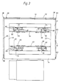
- the packaging device shown in FIGS. 1 to 5 comprises a horizontally arranged, rectangular frame 10, each with parallel frame parts 12 and 14 or 16 and 18, which define a frame opening 20.
- the frame 10 is movably supported on a stand 22 in the vertical direction, as indicated by the double arrow A.
- the stacked packaged goods 24 to be packaged which is placed on a pallet 26, are arranged below the frame opening 20.
- the pallet 26 is packed together with the packaged goods 24.
- the packaged goods 24 can be positioned in the packaging position below the frame opening 20 by means of a transport device 28 and, after the packaging has been completed, is conveyed further via this transport device 28.
- the packaging material used is a tubular film 30, which is wound on a supply roll 32 and fed via deflection elements 34, 36, 38 such as slide rails and rollers to a horizontal bracket 40 attached to the upper end of the stand 22 and protruding forward in the same direction as the frame 10 becomes.
- the tubular film 30 consists of polyethylene and has a thickness between 80 ⁇ and 150 ⁇ .
- the tubular film 30 is folded in its folded state such that it has a double fold on each side, i. H. on each side an inwardly folded edge 42 and two outwardly facing edges 44, 46, as can be seen in particular from FIG. 4.
- console 40 In addition to suitable guide devices (not shown in more detail), devices (not shown) for cutting and, if necessary, welding the hose in the transverse direction are provided within the console 40.
- brackets 48, 50 Arranged on the frame 10 are two brackets 48, 50 which are parallel to one another and to the frame parts 12, 14 and which can be moved on guides 52 arranged along the frame parts 16, 18 by means of suitable control cylinders 54.
- the two brackets 48, 50 can accordingly be moved towards and away from each other, as indicated by the double arrows B in FIG. 1.
- a chain 64 and 66 connecting gears 56 to 62, the gears 56 and 58 on the one hand and 60 and 62 on the other hand, and a shaft, which couples the gears 58 and 60 to one another and is mounted parallel to the frame part 12 on the front of the frame 10 via bearings 68 70 existing synchronization unit, the two consoles 48, 50 move synchronously.
- Each of the consoles carries two suction boxes 72, 74 and 76, 78, respectively, which contain a suction fan (not shown in more detail).
- the suction boxes 72, 74 and 76, 78 are each slidably supported in the longitudinal direction of the associated bracket 48 or 50 via guides 80, 82, the suction boxes being moved by means of cylinder units 84, cf. Fig. 1.
- the suction boxes 72 and 74 or 76 and 78 can thus be moved towards or away from each other, the movement of all suction boxes 72 to 78 preferably being carried out synchronously.
- the suction boxes 72 to 78 each have a vertical suction opening, which points towards the interior of the frame opening 20.
- a pivotable finger element 86 is mounted, which, as can be seen in particular from FIG. 3 in connection with FIG. 2, consists of a horizontal, parallel to the frame parts 12 and 14, with the free end to the inside the frame opening 20 indicating the non-use position (FIG. 3) can be pivoted into a vertically upward functional position (FIGS. 1 and 2).
- An actuating cylinder 88 is provided for actuating each finger element 86.
- Each finger element 86 is arranged in a plane that is slightly spaced from the suction opening of the associated suction box and is located in its horizontal position below the suction box and in its vertical functional position opposite the respective suction box.
- a gripper 90 which can be pivoted about a vertical axis and is bent at right angles, is further arranged, the structure of which results in particular from FIGS. 4 and 5.
- These grippers 90 can be pivoted from a lateral rest position in the direction of the arrow according to FIG. 4 into a clamping position in which they clamp the outer edges 44, 46 of the tubular film 30 on the respectively assigned suction box.
- a horizontally arranged shaft 92 and 94 which runs in the longitudinal direction of the console and is each drivable by means of a motor 96, 98, is arranged in each console 48, 50.
- Each shaft 92, 94 runs just below the suction boxes assigned to it and is opposite the assigned finger elements 86. In the area of the suction boxes or the finger elements, each shaft 92, 94 is surrounded by a friction layer 92a, 94a.
- each shaft 92, 94 is resiliently mounted in such a way that it can deflect outwards, in particular in the horizontal direction, ie away from the frame opening 20.
- the shafts 92, 94 are spring-loaded in such a way that they can deflect upwards in the vertical direction in order to enable increased material absorption on the finger elements 86.
- the frame 10 itself is designed as a shrink frame, for which purpose suitable gas burners are arranged within the frame 10 and can be activated at short notice, so that when the gas burners are activated, the film material located in the area of the frame opening shrinks due to the action of heat.
- pivotable centering vanes 100, 102 are arranged, which have the effect that the tubular film to be supplied to the frame 10 is fed centrally.
- the two centering vanes are brought together so closely that between them there is only one slot through which the tubular film is guided downwards.
- these centering vanes 100, 102 are folded in such a way that they assume a wedge-shaped configuration and, if necessary, conduct heat rising upwards to the side.
- the device described above works fully automatically.
- the reference number 104 denotes a control panel arranged on the stand 22 with program control.
- the device described in connection with FIGS. 1 to 5 operates as follows: At the start of operation, the frame 10 is in its upper position, for example the position shown in FIGS. 1 and 2 above the packaging material 24. Tubular film 30 is fed via the bracket 40 to the frame opening 20 until the lower edge of the tubular film 30 is approximately the same the plane of the waves 92, 94 is flush. In this position, the two brackets 40, 42 are sufficiently spaced from one another to ensure that the tubular film can be passed freely.
- the suction boxes whose blowers have already been brought up to full speed, but the suction side is still blocked, are fed towards one another. This is done by the brackets 48, 50 approaching one another, the suction boxes being able to be displaced in the transverse direction into the required position at the same time if required.
- the suction side is opened via a pneumatic control, so that a vacuum is suddenly created at the openings of the suction boxes and the tubular film is immediately sucked in.
- the grippers 90 are activated so that they pivot in the direction of the arrows according to FIG. 4 and thereby the areas the edges 44, 46 clamp on the suction boxes.
- the consoles continue their outward movement until the film cross-section is opened so far that the finger elements 86 can pivot securely into the interior of the tubular film. This pivoting of the finger elements into the interior of the tubular film can take place simultaneously with the pivoting back of the grippers 90 into their rest position.
- the finger elements are then moved outwards by appropriate movements of the consoles and / or the suction boxes until the tubular film 30 is completely opened. Subsequently, further tubular film material is fed in from above, this tubular film material being placed on the outside of the finger elements. At the same time, the shafts 92, 94 are set in rotation so that the tubular film is pushed onto the finger elements and is held here in the gathered state.
- the finger elements 86 are moved outwards by a suitable method of the brackets 48, 50 and / or the suction boxes 72 to 78, the film gathered on the fingers being stretched by approximately 30% until the film cross section is slightly larger than the cross section of the object to be packaged.
- the frame 10 is then moved downward, the upper end of the tubular film section used being held in a suitable manner at the same time.
- This position fixation of the upper end of the tubular film can either be done by suitable clamping in the area of the upper bracket 40, or else by welding the upper end of the tubular film section in the area of the upper bracket 40, so that the now tubular-like closed tubular film section is pulled over when it is pulled over puts the packing stack on top of the stack.
- the tubular film is pulled over the goods to be packaged. It lies against the surface of the goods to be packaged and is pulled down by the finger elements 86 to the same extent as the frame is moved downwards. It should be noted here that the film is arranged in a gathered state on the finger elements, the waves provided with the friction coating (rubber) stressing the tubular film. These waves now turn in the opposite direction or they release the tubular film step by step by springing away to the side. In this way it is ensured in any case that the film is pulled off the finger elements in a taut state.
- the finger elements are automatically pulled down out of the tubular film and the frame can move up again into its starting position to carry out a new work cycle.
- the upper and lower ends of the tubular film, which protrude beyond the goods to be packaged, are additionally treated by heat shrinking.
- the gas burners located in the frame 10 are activated briefly in a targeted manner when the frame is moved upwards, in order to cause the material located on the underside and / or the top of the object to be packaged to shrink.
- the device comprises a horizontally arranged, rectangular shrink frame 202, which defines an inner frame opening, the dimensions of which are somewhat larger than the outer dimensions of the stacked packaging goods 204 to be packed with shrink film.
- the packaging goods 204 are placed on a pallet 206, which together with the packaging goods 204 is packed.
- the goods to be packaged 204 can be positioned in the packaging position below the opening of the shrinking frame 202 by means of a transport device 208 and, after the packaging has been completed, is conveyed further via the transport device 208.
- a tubular film 210 is used as packaging material, which is wound on a supply roll 212 and is fed to a feed and cutting device 222 via guide rollers 214 to 220.
- the feed and cutting device 222 is from its operating position A shown in dashed lines in FIG. 6, in which it is located above the packaged goods 204 and above the shrinking frame 202, by means of a guide rail device (not shown in detail) and a drive mechanism (also not shown in more detail) in the illustration according to FIG 6 can be shifted to the right into a waiting position B, in which it is located above a stand 224 on which the shrink frame 202 is movably supported in the vertical direction.
- the guide device (not shown in more detail) for the feed and cutting device 222 is carried by a frame 226 which is L-shaped in a side view, the horizontal leg of which spans the shrink frame arrangement 202, the free end of which is fastened to the stand 224 and the vertical leg of which is supported on the floor.
- the feeding and cutting device 222 conventionally comprises, in addition to a drivable, not shown, pair of feed rollers, cutting means for cutting the desired tubular film pieces to length, and optionally a welding device with which the upper end of each cut tubular film piece is closed with its weld seam. An outlet opening for the tubular film is provided on the underside of the feed and cutting device.
- the feed and cutting device 222 is in its operating position A above the packaged goods 204.
- the shrink frame 202 is in the upper starting position shown in FIG. 6.
- the free lower end of the film tube emerging from the feeding and cutting device is gripped, stretched and stretched by means of a suitable gripping device, not shown in detail, mounted on the shrink frame 202 by moving the shrink frame 202 down over the stack-shaped packaged goods 204.
- the feeding and cutting device 222 is moved to the right into the waiting position B in the illustration in FIG. 6, in which is located above the stand 224 arranged on the side of the shrink frame 202.
- the horizontal axis of the guide roller 216 is essentially movably supported in the vertical direction. If the feed and cutting device 222 is moved to the right in the illustration according to FIG. 6, the length of the tubular film 210 which is released in this way is buffered by lowering the guide roller 216 located between the guide rollers 214 and 218. If the feed and cutting device 222 moves to the left again, pulling the tubular film 210 behind it, the movably mounted guide roller 216 is raised against gravity.
- the basic structure of the embodiment according to FIG. 7 corresponds essentially to that according to FIG. 6, so that the same reference numbers are used for the same parts.
- the feed and cutting device 222 ′ is arranged in a stationary manner in a bracket 230 which is fastened to the upper end of the stand 224 and extends parallel to the shrink frame 202 in the horizontal direction.
- the movable guide roller 216 according to FIG. 6 can be dispensed with.
- the tubular film 210 is rather fed to the feed and cutting device 222 'via guide rollers 232, 234.
- blower device On the underside of the console 230 or the feed and cutting device 222 'there is a blower device which, in the case of the exemplary embodiment described here, comprises two blowers 236, 238, each of which has a downward-pointing, horizontally running, substantially over the entire Have width of the feed and cutting device 222 'extending gap-shaped outlet nozzle 240 or 242, whereby an essentially perpendicular downward air flow can be generated.
- the blowers 236, 238 are activated essentially simultaneously with the film feed and remain switched on at least until the shrinking process is completed.
- the downward air flow of the blowers 236, 238 pushes the warm air flow arising during the shrinking downward and to the side, as a result of which the heating of the feed and cutting device 222 ′ by rising, heated air can be significantly reduced.
- FIG. 8 shows a section through one leg of the shrink frame, which is formed overall as a hollow profile, according to a further preferred exemplary embodiment of the invention.
- heating elements provided by gas burners 244, which are evenly distributed in the lower inner region of the hollow profile 246 of each leg of the shrink frame 202 and are supplied with primary air via a line system 248.
- a multiplicity of inlet openings 252 are formed, which can optionally also be designed as a single, continuous opening for each leg of the shrink frame 202.
- Channels 254 connect the inlet openings 252 to horizontally oriented openings 256, in which fans 258 are arranged in the interior of the shrink frame so as to be rotatable about a vertical axis of rotation 260. These fans 258 suck air through the inlet openings 252 from outside the shrink frame 202 into the interior of the hollow profile 246, from where this secondary air between the gas burners 244 and the surrounding wall parts 262 to the outside of the hollow profile 246 in the direction of the packaged goods 204 or the air drawn thereon Tubular film 210 flows out.
- the housing 302 of a shrink frame or the one leg of a shrink frame has an angular cross section and comprises a horizontal leg 304 and a vertical leg section 310 adjoining the shrink frame opening.
- the horizontal leg 304 of the housing 302 is into an outer leg portion 306, which defines the cooling air chamber, and an inner horizontal leg portion 308.
- a burner 312 designed as a gas burner is arranged in the horizontal leg 304 in such a way that its rear region lies in the cooling air chamber 306, while its front region, which comprises the outflow opening, lies in the horizontal leg section 308.
- the outflow direction of the gas burner 312 is also horizontal.
- Cranked baffles 314, 316 are fastened with their rear sections to the upper and lower wall of the cooling air chamber 306, arranged opposite each other and tapering towards the front in the flow direction, so that channels 318 are formed between the baffles 314, 316 and the burner 312, via the fresh air from the cooling air chamber 306 into the horizontal leg section 308 to the heated gases emerging from the burner and initially surrounds them in the form of a cooling air jacket. Otherwise, the cooling air chamber 306 and the horizontal leg section 308 of the housing 302 are separated from one another in a gas-tight manner by means of suitable partition walls 320.
- a deflection plate 324 is attached to the lower housing wall 322 of the horizontal leg section 308 of the housing 302 and extends upward into the vertical leg section 310, but ends at a distance in front of its upper housing wall 326.
- the deflection plate 324 is arranged approximately centrally in the vertical leg section 310.
- the inner housing wall 328 of the vertical leg section 310 is bent in its lower region by approximately 30 ° and then bent in the opposite direction by approximately 90 °.
- the inner section of the lower housing wall 322 is also bent by 30 °, so that the wall sections 330, 332 lie opposite one another in parallel and define a nozzle-shaped outlet opening 334, the outlet direction of which is inclined downward by approximately 30 ° with respect to the horizontal.
- the inner ends of the nozzle-shaped outlet opening 334 lie approximately at the level of the inner housing wall 328.
- All inner walls of the flow channel 336 defined in this way are designed with a heat-insulating material 338, so that the heated gas or gas-air mixture does not come into direct contact with the metallic housing walls on its flow path.
- the gas or air flow undergoes several deflections. First it is deflected from the horizontal direction by 90 ° upwards in a counterclockwise direction, then clockwise by 180 ° downwards, then by around 30 ° again in a clockwise direction and finally by approximately 90 ° in a counterclockwise direction until it reaches the outlet opening 334 leaves. There is thus a total deflection of approximately 390 °, so that the heated gases and the cooling air are mixed particularly well due to eddy formation, which also contributes to the opposite senses of the deflection directions of successive deflections.
- the heated gas-air mixture emerging from the outlet opening 334 thus has a particularly uniform temperature profile, the dimensions of the device being able to be kept compact at the same time and heating of the outer walls of the housing 302 occurring only to a very small extent.
Landscapes
- Engineering & Computer Science (AREA)
- Mechanical Engineering (AREA)
- Physics & Mathematics (AREA)
- Thermal Sciences (AREA)
- Containers And Plastic Fillers For Packaging (AREA)
- Basic Packing Technique (AREA)
- Wrappers (AREA)
Claims (40)
- Procédé pour emballer des articles dans une feuille thermoplastique sous forme de bande ou sous forme tubulaire, caractérisé en ce que la feuille thermoplastique est étirée de 20 à 50% et est appliquée à l'état étiré sur l'ensemble des surfaces latérales de l'article (24), et en ce que seules les régions d'extrémité supérieure et/ou inférieure de l'emballage en feuille sont additionnellement rétractées par application de chaleur après mise en place de la feuille thermoplastique sur l'article (24).
- Procédé selon la revendication 1, caractérisé en ce que la feuille thermoplastique de forme tubulaire (30) est saisie et ouverte par son extrémité libre au cours d'une première étape, contractée au cours d'une seconde étape, étirée selon la section nécessaire alors qu'elle est à l'état contracté au cours d'une troisième étape, et tirée au cours d'une quatrième étape alors qu'elle est à l'état contracté et de préférence du haut vers le bas sur l'article (24) tout en fixant simultanément l'une des extrémités de la bande thermoplastique à découper à longueur par rapport à l'article (24).
- Procédé selon la revendication 2, caractérisé en ce que la feuille thermoplastique de forme tubulaire (30) est soudée transversalement à son extrémité qui est à l'opposé de son extrémité libre avant d'être tirée sur l'article (24).
- Procédé selon la revendication 3, caractérisé en ce que l'ouverture de la feuille thermoplastique de forme tubulaire (30) est obtenue par aspiration appliquée sur le côté extérieur de la feuille thermoplastique (30).
- Dispositif d'emballage d'articles au moyen d'une feuille thermoplastique en forme de bande ou de forme tubulaire pour la mise en oeuvre du procédé selon l'une ou plusieurs des revendications 1 à 4, caractérisé en ce qu'un cadre horizontal (10) pouvant se déplacer en direction verticale sur un support (22) supporte un dispositif pour étirer et appliquer la feuille thermoplastique à l'état étiré sur l'article, et des moyens pour sa rétraction à chaud.
- Dispositif selon la revendication 5, caractérisé en ce qu'un dispositif d'alimentation (34 à 40) destiné à faire avancer la feuille thermoplastique (30) est prévu entre un rouleau de réserve (32) et le cadre (10), en ce que deux consoles (48, 50) parallèles et opposées sont montées sur le cadre (10) et sont mobiles dans les directions qui les rapprochent et les écartent, en ce qu'au moins un dispositif d'aspiration par dépression (72 à 78) est disposé sur chacune des consoles (48, 50), qui coopère avec les côtés extérieurs de la feuille thermoplastique de forme tubulaire, en ce qu'un élément en forme de doigt (86) au moins est prévu sur chaque console (48, 50), qui pénètre à l'intérieur de la feuille thermoplastique de forme tubulaire (30), et en ce qu'en outre un dispositif d'avance (92, 94) pour faire avancer une section dont la longueur peut être choisie à l'avance de la feuille thermoplastique de forme tubulaire (30) sur les éléments en forme de doigts (86) à l'état contracté est monté sur chaque console (48, 50).
- Dispositif selon les revendications 5 et 6, caractérisé en ce que des moyens destinés à la rétraction à chaud sont constitués par des brûleurs à gaz (244, 312) incorporés dans le cadre (10).
- Dispositif selon la revendication 6, caractérisé en ce que deux dispositifs d'aspiration (72, 74 ou 76, 78) et deux éléments en forme de doigts (86) sont respectivement disposés sur chaque console (48, 50) et en ce qu'aussi bien les dispositifs d'aspiration (72 à 78) que les éléments en forme de doigts (86) de chaque console (48, 50) sont guidés de façon mobile en direction longitudinale des consoles, c'est-à-dire transversalement à la direction du mouvement des consoles.
- Dispositif selon la revendication 8, caractérisé en ce qu'un élément en forme de doigt (86) est associé à chaque dispositif d'aspiration (72 à 78) et en ce que l'ensemble constitué par le dispositif d'aspiration et l'élément en forme de doigt peut être déplacé en commun.
- Dispositif selon l'une quelconque des revendications 6 à 9, caractérisé en ce que les éléments en forme de doigts (86) sont montés de façon à pouvoir être pivotés à partir de leur position fonctionnelle verticale vers une position en particulier horizontale.
- Dispositif selon les revendications 9 et 10, caractérisé en ce que chaque élément en forme de doigt (86) est disposé face au dispositif d'aspiration associé (72 à 78).
- Dispositif selon la revendication 6, caractérisé en ce que le dispositif d'avance est constitué par un élément pouvant être entraîné en rotation (92, 94) qui est disposé à proximité d'un élément en forme de doigt (86) de manière que la feuille (30) soit serrée entre lui-même et l'élément en forme de doigt (90).
- Dispositif selon la revendication 12, caractérisé en ce que l'élément pouvant être entraîné en rotation est constitué sous la forme d'un arbre (92, 94) parallèle aux consoles (48, 50) et muni à proximité de chacun des éléments en forme de doigts (86) d'une couche de friction respective (92a, 94a).
- Dispositif selon la revendication 12 ou 13, caractérisé en ce que l'élément pouvant être entraîné en rotation (92, 94) est monté élastiquement dans une direction radiale par rapport à son axe de rotation.
- Dispositif selon les revendications 5 et 6, caractérisé en ce que la feuille thermoplastique de forme tubulaire ou en forme de bande (30) comprend dans son état replié et de chaque côté un double pli, c'est-à-dire sur chaque côté un bord (42) replié vers l'intérieur et deux bords (44, 46) tournés vers l'extérieur, et en ce que des éléments de saisie mobile (90) sont montés sur les consoles (48, 50) de manière à pouvoir serrer les quatre bords (44, 46) tournés vers l'extérieur pour élargir provisoirement la feuille thermoplastique de forme tubulaire.
- Dispositif selon la revendication 15, caractérisé en ce qu'un élément de saisie (90) est monté de façon pivotante sur chaque dispositif d'aspiration (72 à 78)
- Dispositif selon la revendication 15, caractérisé en ce que le matériau (30) de la feuille est du polyéthylène d'une épaisseur comprise entre 50 µ et 250 µ, et de préférence entre 80 µ et 150 µ.
- Dispositif selon la revendication 5 ou 7, caractérisé en ce que sont prévus des moyens pour protéger le dispositif d'alimentation et de coupe (222, 222') de la chaleur (236, 238, 252) produite lors de la rétraction à chaud.
- Dispositif selon la revendication 18, caractérisé en ce que le dispositif d'alimentation et de coupe (222) peut être déplacé par rapport à l'article à emballer (204) de sa position de fonctionnement (A) située au-dessus de l'article à emballer (204) vers une position (B) qui est largement protégée de l'influence de la chaleur.
- Dispositif selon la revendication 19, caractérisé en ce que le dispositif d'alimentation et de coupe peut être déplacé vers la bobine de réserve (212) à partir de sa position de fonctionnement (A), en particulier en direction horizontale.
- Dispositif selon la revendication 20, caractérisé en ce qu'il est prévu sur le trajet d'amenée de la feuille thermoplastique (210) entre le dispositif d'alimentation et de coupe (222) et la bobine de réserve (212) un dispositif formant tampon (216, 228) pour adapter la longueur du trajet d'amenée entre le dispositif d'alimentation et de coupe (222) et la bobine de réserve (212) quand le dispositif d'alimentation et de coupe (222) occupe des positions différentes (A ou B).
- Dispositif selon la revendication 21, caractérisé en ce que le dispositif formant tampon est constitué par au moins un rouleau de renvoi mobile (216) destiné à la feuille thermoplastique (210).
- Dispositif selon la revendication 18, caractérisé en ce que les moyens de protection contre la chaleur produite par la rétraction à chaud sont constitués par un dispositif à soufflantes (236, 238) qui produit un courant d'air s'éloignant du dispositif d'alimentation et de coupe (222').
- Dispositif selon la revendication 23, caractérisé en ce que le dispositif à soufflantes (236, 238) produit un courant d'air sensiblement vertical et dirigé vers le bas.
- Dispositif selon la revendication 24, caractérisé en ce que le dispositif à soufflantes (236, 238) est associé au dispositif d'alimentation et de coupe (222').
- Dispositif selon la revendication 25, caractérisé en ce que des ouvertures de sortie (240, 242) du dispositif à soufflantes (236, 238) sont disposées de chaque côté de l'ouverture de sortie du dispositif d'alimentation et de coupe (222) destiné à la feuille thermoplastique (210).
- Dispositif selon les revendications 5 et 7, caractérisé en ce que l'air chaud sortant du cadre (202) peut être renvoyé au moins en partie dans ce dernier.
- Dispositif selon l'une quelconque des revendications 5 à 27, caractérisé en ce que le cadre (202) est constitué essentiellement par un profilé creux (246) fermé sur tous ses côtés, en ce que l'air chaud sortant du cadre sort par sa partie inférieure, en ce que des ouvertures d'entrée (252) pour l'air chaud qui remonte sont constituées dans la partie supérieure du côté (250) du cadre (202) situé à l'intérieur et en ce qu'à l'intérieur du cadre (202) sont prévus des moyens (258) pour aspirer l'air chaud par les ouvertures d'entrée (252).
- Dispositif selon la revendication 28, caractérisé en ce qu'au moins un dispositif à soufflantes ou plusieurs ventilateurs (258) sont montés à l'intérieur du cadre (202).
- Dispositif selon la revendication 7, caractérisé en ce que le canal de passage (336) entre les brûleurs à gaz (312) et les ouvertures de sortie (334) est coudé dans son ensemble sur 180°.
- Dispositif selon la revendication 30, caractérisé en ce que le canal de passage (336) comprend un premier coude dans un premier sens et un second coude dans un second sens qui est opposé au premier.
- Dispositif selon la revendication 31, caractérisé en ce que le canal de passage (336) comprend un troisième coude se raccordant au second coude.
- Dispositif selon la revendication 31 ou 32, caractérisé en ce que l'un des coudes, et de préférence le second coude, forme un angle d'environ 180°.
- Dispositif selon l'une quelconque des revendications 31 à 33, caractérisé en ce que l'un des coudes, et de préférence le premier coude qui est raccordé au brûleur (312), forme un angle d'environ 90°.
- Dispositif selon l'une quelconque des revendications 30 à 34, caractérisé en ce que le canal de passage (336) est revêtu au moins en partie et de préférence en totalité d'un matériau calorifuge (338) tel qu'en particulier de l'amiante.
- Dispositif selon l'une quelconque des revendications 30 à 35, caractérisé en ce que le carter (302) est constitué en section sensiblement sous une forme angulaire au moins dans la région du canal de passage (336), en ce que l'ouverture du brûleur (312) est disposée dans un côté (308) de l'angle et la direction de sortie des gaz chauds qui quittent le brûleur (312) concorde sensiblement avec la direction de ce côté (308), en ce que dans l'autre côté (310) de l'angle est montée une plaque de renvoi (324) située à une certaine distance de l'extrémité (326) de ce côté (310) et se raccorde de façon étanche à la paroi (322) du carter qui est à l'opposé de cette extrémité (326), et en ce que l'ouverture de sortie (334) est prévue dans la paroi externe (328) de l'autre côté (310) qui est face à la plaque de renvoi (324), ou de la paroi extérieure (322) du premier côté (328) qui s'y raccorde en direction de la plaque de renvoi (324).
- Dispositif selon la revendication 36, caractérisé en ce que l'ouverture de sortie (334) est prévue dans la région des bords extérieurs des deux côtés (308, 310).
- Dispositif selon la revendication 36 ou 37, caractérisé en ce que les deux côtés (308, 310) de l'angle sont disposés en formant un angle de sensiblement 90°.
- Dispositif selon l'une quelconque des revendications 36 à 38, caractérisé en ce que l'ouverture de sortie (334) est constituée sous forme d'une buse et en te que la direction de la sortie forme un angle aigu ou un angle obtus avec les deux côtés (308, 310).
- Dispositif selon l'une quelconque des revendications 30 à 39, caractérisé en ce qu'un plaque de renvoi (324) destinée aux gaz chauffés est disposée face au brûleur (312) et est montée en totalité à l'intérieur du carter (302).
Applications Claiming Priority (6)
| Application Number | Priority Date | Filing Date | Title |
|---|---|---|---|
| DE19873707877 DE3707877A1 (de) | 1987-03-11 | 1987-03-11 | Verfahren und vorrichtung zum verpacken von gegenstaenden mit einer bahnfoermigen kunststoffolie |
| DE3707877 | 1987-03-11 | ||
| DE3714811 | 1987-05-04 | ||
| DE19873714811 DE3714811C2 (de) | 1987-05-04 | 1987-05-04 | Vorrichtung zum Überziehen und Aufschrumpfen einer Kunststoffolie auf zu verpackendes Gut |
| DE8803121U | 1988-03-08 | ||
| DE8803121U DE8803121U1 (fr) | 1988-03-08 | 1988-03-08 |
Publications (2)
| Publication Number | Publication Date |
|---|---|
| EP0285855A1 EP0285855A1 (fr) | 1988-10-12 |
| EP0285855B1 true EP0285855B1 (fr) | 1992-08-12 |
Family
ID=27195587
Family Applications (1)
| Application Number | Title | Priority Date | Filing Date |
|---|---|---|---|
| EP88103927A Expired - Lifetime EP0285855B1 (fr) | 1987-03-11 | 1988-03-11 | Procédé et appareil pour emballer des articles dans une feuille thermoplastique sous forme de bande tubulaire |
Country Status (3)
| Country | Link |
|---|---|
| EP (1) | EP0285855B1 (fr) |
| DE (1) | DE3873583D1 (fr) |
| ES (1) | ES2033961T3 (fr) |
Families Citing this family (11)
| Publication number | Priority date | Publication date | Assignee | Title |
|---|---|---|---|---|
| DE3918311C3 (de) * | 1988-06-03 | 1997-10-09 | Beumer Maschf Bernhard | Verfahren und Vorrichtung zum Umhüllen von Stückgut, insbesondere Stückgutstapeln, mit einer Stretchfolienhaube |
| DE3917110A1 (de) * | 1989-05-26 | 1990-11-29 | Beumer Maschf Bernhard | Verfahren und vorrichtung zum umhuellen von stueckgut mit einer stretchfolienhaube und hiermit zu bildende verpackungseinheit |
| DE9001321U1 (fr) * | 1990-02-06 | 1990-04-12 | Develog, Reiner Hannen & Cie, Corgemont, Ch | |
| DE9001319U1 (fr) * | 1990-02-06 | 1990-04-12 | Develog, Reiner Hannen & Cie, Corgemont, Ch | |
| DE19859889A1 (de) * | 1998-12-23 | 2000-06-29 | Moellers Maschf Gmbh | Verfahren und Vorrichtung zum Umhüllen eines Stückgutstapels |
| DE19933856A1 (de) * | 1999-07-23 | 2001-01-25 | Beumer Maschf Gmbh & Co Kg | Verfahren zum Umhüllen von Stückgut, insbesondere eines Stückgutstapels, mit einer Stretchfolienhaube, und Vorrichtung zur Durchführung dieses Verfahrens |
| IT1313378B1 (it) * | 1999-09-23 | 2002-07-23 | Sestese Off Mec | Apparecchiatura incappucciatrice combinata |
| ITBO20060095A1 (it) * | 2006-02-10 | 2007-08-11 | Aetna Group Spa | Apparecchiatura per la copertura di gruppi di prodotti con film estensibile. |
| ITMI20121690A1 (it) | 2012-10-09 | 2014-04-10 | Sestese Off Mec | Macchina d'imballaggio incappucciatrice perfezionata, con regolazione in altezza del dispositivo di distribuzione. |
| EP2993134B1 (fr) | 2014-09-05 | 2017-03-01 | OFFICINA MECCANICA SESTESE S.p.A. | Machine de hotte d'extraction |
| CN110589128A (zh) * | 2019-10-10 | 2019-12-20 | 深圳启明整体智慧包装技术有限公司 | 包装设备及其收紧机构 |
Family Cites Families (4)
| Publication number | Priority date | Publication date | Assignee | Title |
|---|---|---|---|---|
| CH528405A (de) * | 1968-07-18 | 1972-09-30 | Alkor Oerlikon Plastic Gmbh | Vorrichtung zum Überziehen eines Schlauches über auf einer Unterlage gestapelte Gegenstände |
| FR2316127A1 (fr) * | 1975-07-04 | 1977-01-28 | Hurdequint Louis | Procede de suremballage d'un fardeau par une gaine etirable, et dispositif de mise en oeuvre du procede |
| DE3115911A1 (de) * | 1981-04-22 | 1982-11-11 | Claus Müller GmbH Transportverpackungs-Systeme, 6653 Blieskastel | Verfahren und vorrichtung zum aufschrumpfen von plastikfolie auf flachpaletten-ladeeinheiten |
| DE3117531A1 (de) * | 1981-05-04 | 1982-11-18 | Kurt Lachenmeier ApS, 6400 Soenderborg | Verfahren und vorrichtung zum verpacken von stapeln u. dgl. mit einer heissschrumpffolie |
-
1988
- 1988-03-11 EP EP88103927A patent/EP0285855B1/fr not_active Expired - Lifetime
- 1988-03-11 ES ES198888103927T patent/ES2033961T3/es not_active Expired - Lifetime
- 1988-03-11 DE DE8888103927T patent/DE3873583D1/de not_active Expired - Lifetime
Also Published As
| Publication number | Publication date |
|---|---|
| ES2033961T3 (es) | 1993-04-01 |
| EP0285855A1 (fr) | 1988-10-12 |
| DE3873583D1 (de) | 1992-09-17 |
Similar Documents
| Publication | Publication Date | Title |
|---|---|---|
| DE4103384C2 (de) | Vorrichtung zum Überziehen von Stretchfolienhauben über einen Gutstapel | |
| DE19732298C1 (de) | Vorrichtung und Verfahren zum Umhüllen eines Stapels | |
| DE3242677C2 (fr) | ||
| EP1940686B1 (fr) | Procédé et dispositif de rétrécissement d une feuille thermorétractile disposée autour d une pile de marchandises, en particulier en palettes | |
| EP0285855B1 (fr) | Procédé et appareil pour emballer des articles dans une feuille thermoplastique sous forme de bande tubulaire | |
| DE2713465A1 (de) | Ofenvorrichtung zum heissaufschrumpfen von thermoplastischen huellenumwicklungen auf glasbehaelter | |
| DE2713407A1 (de) | Verfahren zum heissaufschrumpfen thermoplastischer huellenumwicklungen auf glasbehaelter | |
| DE3543943A1 (de) | Ofen zum aufschrumpfen von etiketten | |
| DE19505240C1 (de) | Folienwickelmaschine zum Umwickeln beladener Paletten | |
| DE2057998B2 (de) | Vorrichtung zum umhuellen von sperrigen oder auf paletten gestapelten gegenstaenden mit schrumpffolie | |
| DE3707877C2 (fr) | ||
| DE19920057A1 (de) | Verfahren und Vorrichtung zur Verpackung von Gegenständen in Schrumpffolie | |
| DE102004025501A1 (de) | Verfahren zum Herstellen von Stehfalten und Messerfaltmaschine mit Fördereinrichtung | |
| DE1679978A1 (de) | Verfahren und Vorrichtung zur Herstellung einer linearen dichten Verbindung zwischen zwei Lagen eines thermoplastischen Materials | |
| DE2645633A1 (de) | Vorrichtung zum zusammenziehen thermoplastischer huellen um behaelter | |
| DE2729964B2 (de) | Vorrichtung zum automatischen Einschlagen einer mit Ware gefüllten Schale in eine Plastikfolie | |
| DE1511843A1 (de) | Geraet zur Herstellung von Schrumpfverpackungen | |
| DE2100977A1 (de) | Verfahren und Vorrichtung zum kontinuierlichen Verpacken eines Verpackungsgutes | |
| EP0378730B1 (fr) | Appareil pour emballer des objets avec une bande tubulaire en matière plastique | |
| EP0564971B1 (fr) | Dispositif et procédé pour fabriquer une pile d'articles | |
| DE3011264C2 (fr) | ||
| DE4345387A1 (de) | Vorrichtung zum Trocknen von auf einer bewegten Förderbahn aufliegenden Produkten, insbesondere der gummierten Leimschichten von Briefumschlägen | |
| DE60317293T2 (de) | Vorrichtung zum Umhüllen einer Ladung mittels einer Kunststofffolie | |
| DE202009008118U1 (de) | Vorrichtung zum Umhüllen von Stückgut | |
| EP2711164B1 (fr) | Dispositif et procédé destinés à ouvrir une zone d'extrémité d'un corps de sachet tubulaire |
Legal Events
| Date | Code | Title | Description |
|---|---|---|---|
| PUAI | Public reference made under article 153(3) epc to a published international application that has entered the european phase |
Free format text: ORIGINAL CODE: 0009012 |
|
| AK | Designated contracting states |
Kind code of ref document: A1 Designated state(s): DE ES FR GB IT SE |
|
| 17P | Request for examination filed |
Effective date: 19881108 |
|
| 17Q | First examination report despatched |
Effective date: 19900731 |
|
| GRAA | (expected) grant |
Free format text: ORIGINAL CODE: 0009210 |
|
| AK | Designated contracting states |
Kind code of ref document: B1 Designated state(s): DE ES FR GB IT SE |
|
| GBT | Gb: translation of ep patent filed (gb section 77(6)(a)/1977) | ||
| REF | Corresponds to: |
Ref document number: 3873583 Country of ref document: DE Date of ref document: 19920917 |
|
| ITF | It: translation for a ep patent filed |
Owner name: PROPRIA PROTEZIONE PROPR. IND. |
|
| ET | Fr: translation filed | ||
| PG25 | Lapsed in a contracting state [announced via postgrant information from national office to epo] |
Ref country code: SE Effective date: 19930312 |
|
| REG | Reference to a national code |
Ref country code: ES Ref legal event code: FG2A Ref document number: 2033961 Country of ref document: ES Kind code of ref document: T3 |
|
| PLBE | No opposition filed within time limit |
Free format text: ORIGINAL CODE: 0009261 |
|
| STAA | Information on the status of an ep patent application or granted ep patent |
Free format text: STATUS: NO OPPOSITION FILED WITHIN TIME LIMIT |
|
| 26N | No opposition filed | ||
| EUG | Se: european patent has lapsed |
Ref document number: 88103927.5 Effective date: 19931008 |
|
| PGFP | Annual fee paid to national office [announced via postgrant information from national office to epo] |
Ref country code: SE Payment date: 19950421 Year of fee payment: 8 |
|
| PGFP | Annual fee paid to national office [announced via postgrant information from national office to epo] |
Ref country code: ES Payment date: 19950428 Year of fee payment: 8 |
|
| PG25 | Lapsed in a contracting state [announced via postgrant information from national office to epo] |
Ref country code: ES Free format text: LAPSE BECAUSE OF NON-PAYMENT OF DUE FEES Effective date: 19960312 |
|
| PGFP | Annual fee paid to national office [announced via postgrant information from national office to epo] |
Ref country code: GB Payment date: 19980302 Year of fee payment: 11 |
|
| PGFP | Annual fee paid to national office [announced via postgrant information from national office to epo] |
Ref country code: FR Payment date: 19980317 Year of fee payment: 11 |
|
| PGFP | Annual fee paid to national office [announced via postgrant information from national office to epo] |
Ref country code: DE Payment date: 19980519 Year of fee payment: 11 |
|
| PG25 | Lapsed in a contracting state [announced via postgrant information from national office to epo] |
Ref country code: GB Free format text: LAPSE BECAUSE OF NON-PAYMENT OF DUE FEES Effective date: 19990311 |
|
| REG | Reference to a national code |
Ref country code: ES Ref legal event code: FD2A Effective date: 19990301 |
|
| GBPC | Gb: european patent ceased through non-payment of renewal fee |
Effective date: 19990311 |
|
| PG25 | Lapsed in a contracting state [announced via postgrant information from national office to epo] |
Ref country code: FR Free format text: LAPSE BECAUSE OF NON-PAYMENT OF DUE FEES Effective date: 19991130 |
|
| REG | Reference to a national code |
Ref country code: FR Ref legal event code: ST |
|
| PG25 | Lapsed in a contracting state [announced via postgrant information from national office to epo] |
Ref country code: DE Free format text: LAPSE BECAUSE OF NON-PAYMENT OF DUE FEES Effective date: 20000101 |
|
| PG25 | Lapsed in a contracting state [announced via postgrant information from national office to epo] |
Ref country code: IT Free format text: LAPSE BECAUSE OF NON-PAYMENT OF DUE FEES;WARNING: LAPSES OF ITALIAN PATENTS WITH EFFECTIVE DATE BEFORE 2007 MAY HAVE OCCURRED AT ANY TIME BEFORE 2007. THE CORRECT EFFECTIVE DATE MAY BE DIFFERENT FROM THE ONE RECORDED. Effective date: 20050311 |