EP2711164B1 - Dispositif et procédé destinés à ouvrir une zone d'extrémité d'un corps de sachet tubulaire - Google Patents
Dispositif et procédé destinés à ouvrir une zone d'extrémité d'un corps de sachet tubulaire Download PDFInfo
- Publication number
- EP2711164B1 EP2711164B1 EP12185656.1A EP12185656A EP2711164B1 EP 2711164 B1 EP2711164 B1 EP 2711164B1 EP 12185656 A EP12185656 A EP 12185656A EP 2711164 B1 EP2711164 B1 EP 2711164B1
- Authority
- EP
- European Patent Office
- Prior art keywords
- suction devices
- oblique direction
- angle
- transporting
- bag body
- Prior art date
- Legal status (The legal status is an assumption and is not a legal conclusion. Google has not performed a legal analysis and makes no representation as to the accuracy of the status listed.)
- Active
Links
- 238000000034 method Methods 0.000 title description 8
- 230000000712 assembly Effects 0.000 claims description 4
- 238000000429 assembly Methods 0.000 claims description 4
- 238000012545 processing Methods 0.000 description 8
- 239000000463 material Substances 0.000 description 6
- 239000004033 plastic Substances 0.000 description 6
- 229920003023 plastic Polymers 0.000 description 6
- 238000003892 spreading Methods 0.000 description 6
- 238000006073 displacement reaction Methods 0.000 description 4
- -1 polyethylene Polymers 0.000 description 4
- 238000000926 separation method Methods 0.000 description 4
- 239000002689 soil Substances 0.000 description 4
- 230000015572 biosynthetic process Effects 0.000 description 3
- 239000004744 fabric Substances 0.000 description 3
- 238000004519 manufacturing process Methods 0.000 description 3
- 239000006223 plastic coating Substances 0.000 description 3
- 239000002985 plastic film Substances 0.000 description 3
- 229920006255 plastic film Polymers 0.000 description 3
- 239000004698 Polyethylene Substances 0.000 description 2
- 239000004743 Polypropylene Substances 0.000 description 2
- 238000010276 construction Methods 0.000 description 2
- 125000004122 cyclic group Chemical group 0.000 description 2
- 238000012423 maintenance Methods 0.000 description 2
- 229920000573 polyethylene Polymers 0.000 description 2
- 229920001155 polypropylene Polymers 0.000 description 2
- 238000012546 transfer Methods 0.000 description 2
- 239000002131 composite material Substances 0.000 description 1
- 238000013461 design Methods 0.000 description 1
- 230000002349 favourable effect Effects 0.000 description 1
- 239000000945 filler Substances 0.000 description 1
- 238000003780 insertion Methods 0.000 description 1
- 230000037431 insertion Effects 0.000 description 1
- 230000002093 peripheral effect Effects 0.000 description 1
- 229920000139 polyethylene terephthalate Polymers 0.000 description 1
- 239000005020 polyethylene terephthalate Substances 0.000 description 1
- 238000003860 storage Methods 0.000 description 1
Images


Classifications
-
- B—PERFORMING OPERATIONS; TRANSPORTING
- B31—MAKING ARTICLES OF PAPER, CARDBOARD OR MATERIAL WORKED IN A MANNER ANALOGOUS TO PAPER; WORKING PAPER, CARDBOARD OR MATERIAL WORKED IN A MANNER ANALOGOUS TO PAPER
- B31B—MAKING CONTAINERS OF PAPER, CARDBOARD OR MATERIAL WORKED IN A MANNER ANALOGOUS TO PAPER
- B31B70/00—Making flexible containers, e.g. envelopes or bags
- B31B70/003—Opening or distending bags
-
- B—PERFORMING OPERATIONS; TRANSPORTING
- B31—MAKING ARTICLES OF PAPER, CARDBOARD OR MATERIAL WORKED IN A MANNER ANALOGOUS TO PAPER; WORKING PAPER, CARDBOARD OR MATERIAL WORKED IN A MANNER ANALOGOUS TO PAPER
- B31B—MAKING CONTAINERS OF PAPER, CARDBOARD OR MATERIAL WORKED IN A MANNER ANALOGOUS TO PAPER
- B31B2150/00—Flexible containers made from sheets or blanks, e.g. from flattened tubes
- B31B2150/001—Flexible containers made from sheets or blanks, e.g. from flattened tubes with square or cross bottom
- B31B2150/0014—Flexible containers made from sheets or blanks, e.g. from flattened tubes with square or cross bottom having their openings facing transversally to the direction of movement
-
- B—PERFORMING OPERATIONS; TRANSPORTING
- B31—MAKING ARTICLES OF PAPER, CARDBOARD OR MATERIAL WORKED IN A MANNER ANALOGOUS TO PAPER; WORKING PAPER, CARDBOARD OR MATERIAL WORKED IN A MANNER ANALOGOUS TO PAPER
- B31B—MAKING CONTAINERS OF PAPER, CARDBOARD OR MATERIAL WORKED IN A MANNER ANALOGOUS TO PAPER
- B31B2150/00—Flexible containers made from sheets or blanks, e.g. from flattened tubes
- B31B2150/003—Flexible containers made from sheets or blanks, e.g. from flattened tubes made from tubular sheets
-
- B—PERFORMING OPERATIONS; TRANSPORTING
- B31—MAKING ARTICLES OF PAPER, CARDBOARD OR MATERIAL WORKED IN A MANNER ANALOGOUS TO PAPER; WORKING PAPER, CARDBOARD OR MATERIAL WORKED IN A MANNER ANALOGOUS TO PAPER
- B31B—MAKING CONTAINERS OF PAPER, CARDBOARD OR MATERIAL WORKED IN A MANNER ANALOGOUS TO PAPER
- B31B2160/00—Shape of flexible containers
- B31B2160/20—Shape of flexible containers with structural provision for thickness of contents
Definitions
- the invention relates to a device for opening an end portion of a tubular bag body, which end region extends between an open hose end and a bottom center line, with a transport device on which the bag body with adjacent hose walls at a transport speed in a transport direction is transportable, wherein the bottom center line in the transport direction aligned, and with transversely to the transport direction reciprocally driven suction means which are movable toward each other until they abut against the tube walls of the intermediate end portion of the bag body and thereafter, while exerting a suction force on the respective tube wall away from each other, whereby they pull the tube walls away from each other, wherein the suction means are additionally movable in an oblique direction, which is aligned at an angle to the bottom center line, back and forth.
- Such devices are from the documents DE 974 780 C and DE 10 91 422 B known.
- Chest bags also called cross-bottom bags, are bags of cuboidal shape which are made in bag making machines by providing tubular bag bodies whose end portions are opened and folded into cross bottoms. The bag bodies are guided lying flat when folding through the clothing plant, so that the tube walls of the tubular bag body abut each other, especially at the end portions of the tubular bag body.
- the two tube walls are separated from each other at the end regions of the tubular bag body and folded over 180 ° with respect to each other, usually one of the two tube walls is folded over with the help of a spreading tool as a side flap on itself, creating an open bottom, in which the another hose wall forms a second side flap.
- valve sheets can be inserted for the production of box valve bags, which are formed by further folding operations to a valve through which the bags can be filled by means of a filler neck.
- the final bottom configuration is made by overlapping the bottom side flaps.
- the overlapping bottom side flaps are glued or welded depending on the material.
- bottom cover sheets can be placed on the overlapping bottom side flaps and adhesively bonded or welded thereto.
- the bottom opening device with the aid of which the two layers are separated from one another at the end region of the tubular bag body, is designed as a pneumatic bottom opening device in which suction devices lying opposite each other with respect to the material layers to be separated are provided, which engage the tube walls of the bag body and the sequence are moved apart, whereby the tube walls are separated from each other, so that the spreading tool can intervene therebetween.
- Known floor opening devices such as the AT 408 427 B can be seen, are relatively large-sized constructions in which a linear opening movement is realized by means of cylinder / piston units. It is obvious that such a solution is relatively bulky and cost and maintenance intensive.
- the present invention is therefore an object of the invention to provide a bottom opening device for bag making, with a continuous operation of the system is reliably ensured at a high production rate, the bottom opening device should be simple, inexpensive and robust and wear resistant as possible. Furthermore, the bottom opening device should also allow the safe opening of different widths of floors and a correct transfer to the following processing station and of course be suitable for continuous operation.
- the present invention solves this object by further developing the above-mentioned device and the method mentioned above for opening an end portion of a tubular bag body by the suction means in addition to their transverse mobility in an oblique direction, which is aligned on the one hand in the transport direction and on the other hand at an angle to the bottom center line , are designed to be movable back and forth, wherein the opposing suction devices are each arranged on a holder which is hingedly connected to first ends of two parallel pivot arms, of which at least one is driven to pivot transversely to the transport direction, said second ends of the pivot arms articulated with a support carriage are connected, which carrier carriage in a guide rail in the oblique direction is driven to move back and forth.
- the point of application of the suction devices on the tube walls can be controlled with respect to the mid-center line and even adjusted during operation, whereby the opening device can be adapted to end regions of different lengths which are formed into bag bases of different widths. Furthermore, it is possible with the opening device according to the invention to adjust the points of application of the suction devices on the tube walls to be separated so that they are as close as possible to the outer end of the bag body, whereby the precision of the opening operation is increased.
- the device according to the invention offers robustness, speed and multiple adjustment during operation, with a pivot arm being expediently driven pivotably via an angle lever.
- the inventive device offers in addition to a relatively simple, inexpensive construction has the advantage that due to the parallelogram geometry of the structure of holder, swivel arms and carrier carriage during pivoting this Parallelogrammmaschine in the course of the opening process, the orientation of the suction with respect to maintained to be separated from each other tube walls, so that even if relatively wide end portions are raised, a safe and torsion-free opening or separation of the adjoining tube walls takes place and can intervene reliably in the later processing the spreading tools.
- the device according to the invention is particularly suitable for processing bag bodies made of stretched plastic tapes and / or plastic film, wherein the plastic material is preferably selected from polyethylene, polypropylene and / or PET. Also composites of the materials mentioned can be processed, and the bag body can be provided with a plastic coating.
- the web of stretched plastic tape may be provided with a plastic coating to achieve the tightness of the web, to improve printability, and to adjust other desirable properties. Sacks of stretched plastic tape have superior strength over paper or plastic film bags, but tend to slip in the manufacturing process and are also harder to fold than, for example, paper. Therefore, it is of particular advantage that these bag bodies can be handled by the present invention.
- bottoms can be formed at both opposite end regions of the tubular sack body, or a bottom can be formed only at one end region.
- the opening device according to the invention can be adapted particularly easy for the mounting of different wide bottoms and different width bag bodies become.
- a shallow angle is chosen against the mid-ground line, and for steeper soils, a steeper angle can be set.
- the precision of the opening operation is increased when the angle of the oblique direction to the center of the ground line is less than 45 °, preferably less than 30 °.
- the opening device regardless of the setting of the angle described above, correctly transfers the opened end region to a subsequent processing station, in particular to spreading tools, without an unguided or undefined state between the opening of the end region and its further processing must be accepted.
- the suction devices are moved during their contact with the tube walls at a speed in the oblique direction whose speed component in the transport direction is equal to the transport speed.
- the suction devices are moved transversely to the transport direction by means of transverse guide means
- the transverse guide means preferably comprise rails, pivot arms and / or transversely arranged to the transport direction piston-cylinder assemblies arranged at the free ends of the piston suction devices
- the inclined guide means preferably comprise rails, pivot arms and / or obliquely arranged piston-cylinder arrangements with suction devices arranged at the free ends of the pistons.
- the pivot arms are displaceable together in the oblique direction and therefore can in continuous operation of a bag making machine in a simple manner during the opening process with the continuously conveyed bag bodies be moved.
- the pivot arms of the respective parallelogram unit can be driven in any desired manner. It is conceivable to actuate the pivot arms by means of servo motors or motor / gear groups, hydraulic or pneumatic cylinder-piston units or via cables. According to a preferred embodiment of the present invention, however, it is provided that in each case a pivoting arm is driven via an angle lever and connected to the angle levers rods which are hinged to a control slide. Due to the parallelogram arrangement of the pivot lever, it is sufficient to actuate only a single pivot arm of a parallelogram unit, since the other elements of the parallelogram are forcibly guided.
- This preferred embodiment of the drive with an angle lever, rods and control slide is robust and maintenance-free.
- the pivoting of the Pivot lever by means of control slide which is independent of the carriage slidable, represents a rectilinear displacement operation.
- the carrier carriage and the control slide are guided on a common guide rail.
- peripheral drives in particular toothed belt drives, are preferred as drives for the carrier slide and the control slide.
- Timing belt drives are known to be reliable even with long running times and can be quickly replaced if necessary without the need for specially trained personnel.
- the displacement of the carrier carriage and the control slide could also be done by means of cylinder / piston drives, spindle drives or servomotors.
- the present invention is preferably further developed such that opposing suction devices are arranged offset from one another, whereby they attack each other offset to the tube walls to be separated. With such a positioning of the suction devices to each other succeeds a reliable separation of the tube walls.
- the guide rail is adjustable by means of adjustable storage with an adjustable angle in the oblique direction to the bottom center line.
- the adjustable bearing comprises elongated holes with recesses defined by recesses, a rapid change between different settings of the angle to the ground center line is possible. Switching between positions can be done with simple tools and, if necessary, by a single person.
- a particularly advantageous embodiment can be achieved if the mounting of the guide rail is adjustable by means of a motor drive.
- the adjustment of the angle can be accomplished without the use of tools, and it also it is possible to make the setting computer-controlled to the desired bottom width, even during operation of the bag making machine.
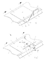
- FIG. 1 to FIG. 3 the essential features of the device 1 according to the invention shown only schematically.
- the device 1 comprises a transport device 2 in the form of a conveyor belt which moves continuously at a transport speed V in a transport direction T.
- a transport device 2 On the transport device 2 are tubular bag body 10 in flat-lying state with its longitudinal extent L transverse to the transport direction T.
- the bag body 10 are secured on the conveyor belt by means not shown holding against slipping.
- the tubular bag body 10 are made for example of fabric of stretched plastic tape.
- the plastic tapes may comprise a polyethylene or polypropylene or PET material.
- the fabric has a plastic coating.
- the tubular bag body 10 may alternatively be made of plastic film.
- the tubular bag body 10 has two opposing open end portions 10e, 10f.
- the end portion 10e extending between an open tube end 10k and a bottom center line 10j is to be formed into a cross bottom.
- the end portion 10f may also be formed into a cross bottom in the same manner as the end portion 10e, thereby producing a box bag or box valve bag.
- FIG. 1 It can be seen that the tubular bag body 10 initially rests flat on the transport device 2 in a first plane ⁇ 1. In this flat lying state, a first and a second tube wall 10a, 10b abut each other. Then, the end portion 10e of the tubular bag body 10 is brought by means of a bottom center bar 12 and baffles 11a, 11b along a bottom center line 10j from the first plane ⁇ 1 of the flat bag body in a substantially orthogonal extending second plane ⁇ 2. It should be mentioned at this point that the formation of the soil is possible even without this folding process.
- FIG. 2 shows the bag body 10 with end portion 10e folded completely along the bottom center line 10j orthogonally upwards (into the second plane ⁇ 2).
- the floor center strip 12 continues in the transport direction T and now, in cooperation with the deflection plate 11a, has the task of holding the end area 10e of the bag body 10 folded into the second plane ⁇ 2 in this angular position relative to the first plane ⁇ 1, in which the bag body 10 lies ,
- the opening device 1 further comprises two suction devices 13, 14, which are transversely movable transversely to the transport direction T on symbolically illustrated transverse guide means 15, 16.
- the transverse guide means 15, 16 may be formed, for example, as rails or pivot arms.
- transverse guide means 15, 16 piston-cylinder assemblies, wherein the suction means 13, 14 sit at the free ends of the pistons and in such a way transversely to the transport direction T back and forth are movable.
- the transverse guide means 15, 16 are by means of inclined guide means 17, 18 in an oblique direction S, which is aligned on the one hand in the transport direction T and on the other hand at an angle ⁇ to the bottom center line 10j or the imaginary extension of the bottom centerline, back and forth.
- the bottom center line 10j or its imaginary extension is aligned in the plane ⁇ 1 in the transport direction T.
- the oblique guide means 17, 18 may be formed, for example, as rails, pivot arms or piston-cylinder arrangements.
- FIG. 2 a process step is shown, in which the two suction devices 13, 14 have been brought into contact with the first tube wall 10a and the second tube wall 10b from opposite sides in the end region 10e.
- a vacuum is generated at the suction devices 13, 14, so that the first suction device 13 sucks in the first hose wall 10a and the second suction device 14 sucks in the second hose wall 10b.
- the suction devices 13, 14, when in contact with the tube walls 10a, 10b are moved at a speed in the oblique direction S whose speed component in the transporting direction T is equal to the transporting speed V, so that There can be no distortion of the tube walls 10a, 10b.
- the two suction devices 13, 14 start to move away from one another transversely to the transport direction V (arrows P1 or P2), in each case pulling a hose wall 10a, 10b with it and thereby open the end portion 10e of the tubular bag body 10.
- the suction devices 13, 14 in the oblique direction S can be the point of application of the suction devices 13, 14 on the tube walls 10a, 10b with respect to the bottom center line Control 10j and even adjust during operation, whereby the opening device 1 at different lengths end portions, which are formed to different widths bag bottoms, is customizable.
- the attack points of the suction devices 13, 14 to be separated at the tube walls 10a, 10b to be adjusted so that they are as close to the outer end of the bag body, whereby the precision of the opening operation is increased. It does not matter whether the end portion 10e is folded before opening along the bottom center line 1j with respect to the rest of the bag body 10 (as shown here) or not. If the end region 10e had not yet been folded upon opening, that is to say if it were still in the plane ⁇ 1, then the opening device would be arranged rotated so that the suction devices would engage from above and below. It only needs to be ensured that at least part of the end region 10e is exposed.
- FIG. 3 shows the end portion 10e of the tubular bag body 10 in the open state in which a clearance 10g is formed between the tube walls 10a, 10b. It can also be seen in this illustration that meanwhile the vacuum has been switched off by the suction devices 13, 14 and the two suction devices 13, 14 have disengaged from the hose walls 10a, 10b and can therefore be moved back in the oblique direction S. to be opened for opening the end portion of the next bag body.
- the further processing of the end region 10e for the formation of the soil takes place at a downstream of the bottom opening device processing station, which in FIG. 3 schematically with generally designated 19 and is not the subject of the present invention.
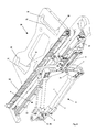
- FIGS. 4 to 6 a bottom opening unit as part of the opening device 1 according to the invention.
- This bottom opening unit 20 is in Fig. 4 in a perspective view, in Fig. 5 in a somewhat simplified soffit and in Fig. 6 shown in a schematic side view.
- the suction devices 13, 14 are each arranged on a holder 3 and facing each other. Since the bottom opening unit 20 is constructed largely symmetrical, the relevant components are hereinafter called only once for the purpose of description. However, it is obvious that components of each side not described are structurally and functionally identical.
- the holder 3 is pivotally connected to first ends of two parallel pivot arms 4, 5, of which at least one (here the pivot arm 4) is driven to be pivotable transversely to the transport direction T.
- the second ends of the pivot arms 4, 5 are pivotally connected to a carrier carriage 7, which carrier carriage 7 is driven to move back and forth in a guide rail 22 in the oblique direction S.
- the bottom opening unit 20 is fixed to a support 30 so that the guide rail 22 is aligned in the transport direction T and parallel to the oblique direction S (see FIG Fig. 6 ).
- the holder 3, the two pivot arms 4 and 5 and the carrier slide 7 form a parallelogram unit 8, in which the parallelogram configuration is maintained during pivoting.
- the pivoting of the pivot arms 4 and 5 takes place according to the device according to the invention FIG. 4 via an angle lever 23 attached to the swivel arm 4, which lever is connected to a rod 9, which is articulated to a control carriage 21.
- the control carriage 21 is mounted in the guide rail 22 to move back and forth.
- the carrier carriage 7 and the control carriage 21 are driven by means of a toothed belt drive 24, 25.
- the line A1 is parallel to the longitudinal axis of the guide rail 22 and parallel to the oblique direction S, whereby the guide rail 22 together with the control slide 21, the carriage 7, the linkage 9, the Parallelogrammtechniken 8 and disposed thereon suction devices 13 and 14 at an angle ⁇ are moved to the bottom center line 10j or level ⁇ 1, which allows the precise opening of different width bag bodies 10. It is important here that the guide rail 22 is parallel to the oblique direction S. To change the angle ⁇ , the bottom opening unit 20 is screwed with its upper recesses 28 on the support 30, whereby two bearing points are defined, which are interconnected by the line A2.
- the self-adjusting angle ⁇ of the longitudinal axis of the guide rail 22 and thus also the oblique direction S to the bottom center line 10j is smaller by an angle ⁇ than in the first bearing. It remains ensured despite different angle settings that the bottom opening unit 20 regardless of the above-described adjustment of the angle ⁇ opens the end portion 10e so that it is passed without an unguided or undefined state to the subsequent spreading tools.
Landscapes
- Supplying Of Containers To The Packaging Station (AREA)
- External Artificial Organs (AREA)
- Bag Frames (AREA)
Claims (13)
- Dispositif (1) permettant d'ouvrir une partie d'extrémité (10e) d'un corps de sac tubulaire (10), ladite partie d'extrémité (10e) s'étendant entre une extrémité (10k) de corps tubulaire ouverte et une ligne médiane du fond (10j), comprenant un dispositif de transport (2), sur lequel le corps de sac (10) peut être convoyé avec une vitesse de transport (V) dans une direction de transport (T), les parois de tube (10a, 10b) étant disposées l'une contre l'autre, la ligne médiane du fond (10j) étant orientée dans la direction de transport (T), et comprenant des dispositifs d'aspiration (13, 14) entraînés en va-et-vient transversalement à la direction de transport (T), déplaçables l'un vers l'autre jusqu'à être en contact avec les parois de tube (10a, 10b) de la partie d'extrémité (10e) du corps de sac (10) disposée entre eux, puis éloignables l'un de l'autre en exerçant une force d'aspiration sur la paroi de tube respective, les parois de tube étant ainsi écartées l'une de l'autre par eux, les dispositifs d'aspiration (13, 14) étant en outre déplaçables en va-et-vient dans une direction oblique (S) formant un angle (α) avec la ligne médiane du fond (10j), caractérisé en ce que la direction oblique (S) est orientée dans la direction de transport (T) et en ce que les dispositifs d'aspiration (13, 14) opposés l'un à l'autre sont disposés chacun contre un support (3) raccordé de manière articulée à des premières extrémités de deux bras pivotants parallèles (4, 5), dont au moins l'un est entraîné en pivotement transversalement à la direction de transport (T), des deuxièmes extrémités des bras pivotants (4, 5) étant raccordées de manière articulée à un chariot de support (7), ledit chariot de support (7) étant entraîné en va-et-vient dans la direction oblique (S) dans un rail de guidage (22).
- Dispositif selon la revendication 1, caractérisé en ce que chaque bras pivotant (4, 5) est entraîné en pivotement par un levier coudé (23).
- Dispositif selon la revendication 2, caractérisé en ce que les leviers coudés (23) sont soumis par des bielles (9) à un mouvement oscillant par rapport à un chariot de commande (21) déplaçable en va-et-vient dans un rail de guidage (22).
- Dispositif selon la revendication 1 en relation avec la revendication 3, caractérisé en ce que le chariot de support (7) et le chariot de commande (21) sont coulissés sur un rail de guidage (22) commun.
- Dispositif selon l'une des revendications précédentes, caractérisé en ce que le chariot de support (7) et/ou le chariot de commande (21) sont déplacés en va-et-vient au moyen d'entraînements rotatifs, en particulier d'entraînements à courroie dentée (24, 25).
- Dispositif selon l'une des revendications précédentes, caractérisé en ce que le rail de guidage (22) est orientable suivant un angle (α) réglable dans la direction oblique (S) par rapport à la ligne médiane du fond (10j), manuellement ou par moteur au moyen d'un palier réglable.
- Dispositif selon la revendication 6, caractérisé en ce que le palier réglable comporte des trous oblongs (27) avec des points de palier définis par des évidements (28).
- Dispositif selon l'une des revendications précédentes, caractérisé en ce que l'angle (α) de la direction oblique (S) est réglable par rapport à la ligne médiane du fond (10j).
- Dispositif selon l'une des revendications précédentes, caractérisé en ce que l'angle (α) de la direction oblique (S) est inférieur à 45°, préférentiellement inférieur à 30° par rapport à la ligne médiane du fond (10j).
- Dispositif selon l'une des revendications précédentes, caractérisé en ce que, lorsqu'ils se trouvent en contact avec les parois de tube (10a, 10b), les dispositifs d'aspiration (13, 14) sont déplacés dans la direction oblique (S) avec une vitesse dont la composante dans la direction de transport (T) est égale à la vitesse de transport (V).
- Dispositif selon l'une des revendications précédentes, caractérisé en ce que les dispositifs d'aspiration (13, 14) sont déplaçables transversalement à la direction de transport (T) par des moyens de guidage transversal (15, 16), lesdits moyens de guidage transversal comprenant préférentiellement des rails, des bras pivotants et/ou des montages piston-cylindre disposés transversalement à la direction de transport (T) avec des dispositifs d'aspiration (13, 14) placés aux extrémités libres des pistons.
- Dispositif selon l'une des revendications précédentes, caractérisé en ce que les dispositifs d'aspiration (13, 14) sont déplaçables dans la direction oblique (S) par des moyens de guidage oblique (17, 18), lesdits moyens de guidage oblique comprenant préférentiellement des rails, des bras pivotants et/ou des montages piston-cylindre disposés dans la direction oblique (S) avec des dispositifs d'aspiration (13, 14) placés aux extrémités libres des pistons.
- Dispositif selon l'une des revendications précédentes, caractérisé en ce que les dispositifs d'aspiration (13, 14) opposés l'un à l'autre sont décalés l'un par rapport à l'autre.
Priority Applications (7)
| Application Number | Priority Date | Filing Date | Title |
|---|---|---|---|
| ES12185656.1T ES2592534T3 (es) | 2012-09-24 | 2012-09-24 | Dispositivo y procedimiento para abrir una zona de extremo de un cuerpo de bolsa de forma tubular |
| EP12185656.1A EP2711164B1 (fr) | 2012-09-24 | 2012-09-24 | Dispositif et procédé destinés à ouvrir une zone d'extrémité d'un corps de sachet tubulaire |
| CN201380049509.9A CN104812561B (zh) | 2012-09-24 | 2013-09-04 | 用于打开管状袋体的端部区域的装置 |
| PCT/EP2013/068303 WO2014044532A1 (fr) | 2012-09-24 | 2013-09-04 | Dispositif permettant d'ouvrir une partie d'extrémité de corps de sac tubulaire |
| TW102133905A TWI477424B (zh) | 2012-09-24 | 2013-09-18 | 管形袋體之末端區域之開啟裝置 |
| PH12015500558A PH12015500558B1 (en) | 2012-09-24 | 2015-03-13 | Device for opening an end region of a tubular bag body |
| IN2703DEN2015 IN2015DN02703A (fr) | 2012-09-24 | 2015-04-02 |
Applications Claiming Priority (1)
| Application Number | Priority Date | Filing Date | Title |
|---|---|---|---|
| EP12185656.1A EP2711164B1 (fr) | 2012-09-24 | 2012-09-24 | Dispositif et procédé destinés à ouvrir une zone d'extrémité d'un corps de sachet tubulaire |
Publications (2)
| Publication Number | Publication Date |
|---|---|
| EP2711164A1 EP2711164A1 (fr) | 2014-03-26 |
| EP2711164B1 true EP2711164B1 (fr) | 2016-06-22 |
Family
ID=47002662
Family Applications (1)
| Application Number | Title | Priority Date | Filing Date |
|---|---|---|---|
| EP12185656.1A Active EP2711164B1 (fr) | 2012-09-24 | 2012-09-24 | Dispositif et procédé destinés à ouvrir une zone d'extrémité d'un corps de sachet tubulaire |
Country Status (7)
| Country | Link |
|---|---|
| EP (1) | EP2711164B1 (fr) |
| CN (1) | CN104812561B (fr) |
| ES (1) | ES2592534T3 (fr) |
| IN (1) | IN2015DN02703A (fr) |
| PH (1) | PH12015500558B1 (fr) |
| TW (1) | TWI477424B (fr) |
| WO (1) | WO2014044532A1 (fr) |
Cited By (1)
| Publication number | Priority date | Publication date | Assignee | Title |
|---|---|---|---|---|
| EP3498624A1 (fr) | 2017-12-14 | 2019-06-19 | Starlinger & Co Gesellschaft m.b.H. | Sac pour matière en vrac |
Families Citing this family (2)
| Publication number | Priority date | Publication date | Assignee | Title |
|---|---|---|---|---|
| EP3269539B1 (fr) | 2016-07-14 | 2019-02-20 | Starlinger & Co. Gesellschaft m.b.H. | Dispositif destiné à ouvrir une zone d'extrémité d'un corps de sachet tubulaire |
| CN111038001A (zh) * | 2019-12-31 | 2020-04-21 | 常州骓慕机械有限公司 | 一种非插入式三角成型装置和方法 |
Family Cites Families (11)
| Publication number | Priority date | Publication date | Assignee | Title |
|---|---|---|---|---|
| DE974780C (de) * | 1950-10-09 | 1961-04-20 | St Regis Paper Co | Maschine fuer die selbsttaetige Bodenbildung von ein- oder mehrlagigen Papiersaecken, insbesondere Ventilsaecken |
| DE1091422B (de) * | 1959-05-19 | 1960-10-20 | Windmoeller & Hoelscher | Vorrichtung zum Voroeffnen der hochgestellten Enden der Schlauchabschnitte in einer Bodenlegemaschine |
| FR2601899A1 (fr) * | 1986-07-24 | 1988-01-29 | Chandellier Antoine | Machine a faconner les soufflets de fond des enveloppes des sachets et sacs en papier comportant trois soufflets |
| JP2793121B2 (ja) * | 1994-03-07 | 1998-09-03 | 株式会社フジキカイ | 折畳みケースの開口装置 |
| CZ289183B6 (cs) | 1995-01-25 | 2001-11-14 | Windmöller & Hölscher | Zařízení na vytahování konců plochých hadicových odřezků |
| SE514429C2 (sv) * | 1999-06-11 | 2001-02-19 | Tetra Laval Holdings & Finance | Anordning för vikning av flexibelt förpackningsmaterial |
| JP4667067B2 (ja) * | 2005-02-18 | 2011-04-06 | 株式会社ミヤコシ | 角底袋の製袋機 |
| DE102008017445A1 (de) * | 2008-04-03 | 2009-10-15 | Windmöller & Hölscher Kg | Vorrichtung und Verfahren zur Herstellung von Säcken |
| CN101670684B (zh) * | 2009-09-19 | 2011-03-23 | 张列荣 | 一种包装袋的制作工艺 |
| EP2441574B1 (fr) | 2010-10-14 | 2013-05-15 | Starlinger & Co Gesellschaft m.b.H. | Procédé et dispositif de formation de fonds ouverts sur des zones d'extrémité de corps de sachets tubulaires |
| JP5739149B2 (ja) * | 2010-12-10 | 2015-06-24 | テルモ株式会社 | 医療用バッグの製造方法および医療用バッグ |
-
2012
- 2012-09-24 ES ES12185656.1T patent/ES2592534T3/es active Active
- 2012-09-24 EP EP12185656.1A patent/EP2711164B1/fr active Active
-
2013
- 2013-09-04 CN CN201380049509.9A patent/CN104812561B/zh active Active
- 2013-09-04 WO PCT/EP2013/068303 patent/WO2014044532A1/fr active Application Filing
- 2013-09-18 TW TW102133905A patent/TWI477424B/zh active
-
2015
- 2015-03-13 PH PH12015500558A patent/PH12015500558B1/en unknown
- 2015-04-02 IN IN2703DEN2015 patent/IN2015DN02703A/en unknown
Cited By (2)
| Publication number | Priority date | Publication date | Assignee | Title |
|---|---|---|---|---|
| EP3498624A1 (fr) | 2017-12-14 | 2019-06-19 | Starlinger & Co Gesellschaft m.b.H. | Sac pour matière en vrac |
| WO2019115105A1 (fr) | 2017-12-14 | 2019-06-20 | Starlinger & Co Gesellschaft M.B.H. | Sac pour matériaux en vrac |
Also Published As
| Publication number | Publication date |
|---|---|
| CN104812561B (zh) | 2016-10-19 |
| EP2711164A1 (fr) | 2014-03-26 |
| WO2014044532A1 (fr) | 2014-03-27 |
| TWI477424B (zh) | 2015-03-21 |
| TW201412608A (zh) | 2014-04-01 |
| CN104812561A (zh) | 2015-07-29 |
| IN2015DN02703A (fr) | 2015-09-04 |
| ES2592534T3 (es) | 2016-11-30 |
| PH12015500558A1 (en) | 2015-05-11 |
| PH12015500558B1 (en) | 2015-05-11 |
Similar Documents
| Publication | Publication Date | Title |
|---|---|---|
| DE3101310C2 (de) | Verpackungsmaschine | |
| DE3041723C2 (de) | Verfahren und Vorrichtung zum Befördern von Stapeln aus bahnförmigen Einheiten | |
| AT406668B (de) | Vorrichtung zur übernahme und beförderung von gegenständen | |
| EP2276628A1 (fr) | Dispositif et procédé pour produire des sacs | |
| WO2012049040A1 (fr) | Procédé et dispositif de formation de fonds ouverts sur des zones d'extrémité de corps de sacs tubulaires | |
| DE4211219C2 (de) | Anordnung zur Handhabung von Flachmaterial | |
| EP3755631A1 (fr) | Dispositif de remplissage et procédé permettant de remplir des sacs dotés respectivement d'une extrémité supérieure non fermée | |
| DE602005003155T2 (de) | Vorrichtung zum Herstellen von Schachteln | |
| EP3672875B1 (fr) | Dispositif d'emballage et procédé destiné à emballer des objets | |
| EP3269539B1 (fr) | Dispositif destiné à ouvrir une zone d'extrémité d'un corps de sachet tubulaire | |
| EP2711164B1 (fr) | Dispositif et procédé destinés à ouvrir une zone d'extrémité d'un corps de sachet tubulaire | |
| EP3372513A1 (fr) | Dispositif de manipulation d'articles et procédé d'échange d'au moins un module de transport et d'au moins un dispositif de travail dudit module | |
| AT515831B1 (de) | Vorrichtung und Verfahren zum Ausbilden einer Bodenöffnung | |
| DE102007027945A1 (de) | Verfahren und Vorrichtung zur Herstellung eines gefalzten Bogens | |
| DE3524203A1 (de) | Vorrichtung zur handhabung flacher, flexibler bahnen | |
| DE2440491C2 (de) | Vorrichtung zur Herstellung von Kreuzboden-Ventilsäcken | |
| WO2010015505A1 (fr) | Coulisseau mobile pour ouvrir les extrémités de pièces tubulaires | |
| DE19828300A1 (de) | Transportvorrichtung für Blattlagen, insbesondere Falzvorrichtung, sowie Verfahren zum Transportieren von Blattlagen, insbesondere zum Herstellen des Falzes | |
| EP3177442B1 (fr) | Procédé de fabrication de sacs ou de poches ainsi que sacs ou poches | |
| DE102008017443A1 (de) | Vorrichtung und Verfahren zur Herstellung von Säcken aus Schlauchstücken | |
| DE69702108T2 (de) | Verfahren und Apparat zur kontaktlosen Verzögerung von flachen Produkten | |
| DE1511802C (de) | Vorrichtung zum Entfalten und Befe stigen der Faltlappen von rechteckformtgen Packungen an deren Stirnwanden | |
| EP3197801B1 (fr) | Dispositif et procédé de séparation de parties d'un produit à plusieurs parties | |
| DE2008135C3 (de) | Verfahren und Vorrichtung zum maschinellen Anlegen und Umfalten eines vorgefalzten Schutzumschlages an ein Buch | |
| DE2621494C2 (de) | Vorrichtung zum Herstellen und Aufbringen von Ventilschläuchen auf Ventilsäcke |
Legal Events
| Date | Code | Title | Description |
|---|---|---|---|
| PUAI | Public reference made under article 153(3) epc to a published international application that has entered the european phase |
Free format text: ORIGINAL CODE: 0009012 |
|
| AK | Designated contracting states |
Kind code of ref document: A1 Designated state(s): AL AT BE BG CH CY CZ DE DK EE ES FI FR GB GR HR HU IE IS IT LI LT LU LV MC MK MT NL NO PL PT RO RS SE SI SK SM TR |
|
| AX | Request for extension of the european patent |
Extension state: BA ME |
|
| 17P | Request for examination filed |
Effective date: 20140901 |
|
| RBV | Designated contracting states (corrected) |
Designated state(s): AL AT BE BG CH CY CZ DE DK EE ES FI FR GB GR HR HU IE IS IT LI LT LU LV MC MK MT NL NO PL PT RO RS SE SI SK SM TR |
|
| REG | Reference to a national code |
Ref country code: DE Ref legal event code: R079 Ref document number: 502012007442 Country of ref document: DE Free format text: PREVIOUS MAIN CLASS: B31B0001000000 Ipc: B31B0001800000 |
|
| GRAP | Despatch of communication of intention to grant a patent |
Free format text: ORIGINAL CODE: EPIDOSNIGR1 |
|
| RIC1 | Information provided on ipc code assigned before grant |
Ipc: B31B 1/80 20060101AFI20160212BHEP Ipc: B31B 29/00 20060101ALI20160212BHEP |
|
| INTG | Intention to grant announced |
Effective date: 20160314 |
|
| GRAS | Grant fee paid |
Free format text: ORIGINAL CODE: EPIDOSNIGR3 |
|
| GRAA | (expected) grant |
Free format text: ORIGINAL CODE: 0009210 |
|
| AK | Designated contracting states |
Kind code of ref document: B1 Designated state(s): AL AT BE BG CH CY CZ DE DK EE ES FI FR GB GR HR HU IE IS IT LI LT LU LV MC MK MT NL NO PL PT RO RS SE SI SK SM TR |
|
| REG | Reference to a national code |
Ref country code: GB Ref legal event code: FG4D Free format text: NOT ENGLISH |
|
| REG | Reference to a national code |
Ref country code: CH Ref legal event code: EP |
|
| REG | Reference to a national code |
Ref country code: IE Ref legal event code: FG4D Free format text: LANGUAGE OF EP DOCUMENT: GERMAN |
|
| REG | Reference to a national code |
Ref country code: AT Ref legal event code: REF Ref document number: 807414 Country of ref document: AT Kind code of ref document: T Effective date: 20160715 |
|
| REG | Reference to a national code |
Ref country code: DE Ref legal event code: R096 Ref document number: 502012007442 Country of ref document: DE |
|
| REG | Reference to a national code |
Ref country code: LT Ref legal event code: MG4D |
|
| REG | Reference to a national code |
Ref country code: NL Ref legal event code: MP Effective date: 20160622 |
|
| PG25 | Lapsed in a contracting state [announced via postgrant information from national office to epo] |
Ref country code: FI Free format text: LAPSE BECAUSE OF FAILURE TO SUBMIT A TRANSLATION OF THE DESCRIPTION OR TO PAY THE FEE WITHIN THE PRESCRIBED TIME-LIMIT Effective date: 20160622 Ref country code: LT Free format text: LAPSE BECAUSE OF FAILURE TO SUBMIT A TRANSLATION OF THE DESCRIPTION OR TO PAY THE FEE WITHIN THE PRESCRIBED TIME-LIMIT Effective date: 20160622 Ref country code: NO Free format text: LAPSE BECAUSE OF FAILURE TO SUBMIT A TRANSLATION OF THE DESCRIPTION OR TO PAY THE FEE WITHIN THE PRESCRIBED TIME-LIMIT Effective date: 20160922 |
|
| REG | Reference to a national code |
Ref country code: DE Ref legal event code: R079 Ref document number: 502012007442 Country of ref document: DE Free format text: PREVIOUS MAIN CLASS: B31B0001800000 Ipc: B31B0050800000 |
|
| PG25 | Lapsed in a contracting state [announced via postgrant information from national office to epo] |
Ref country code: SE Free format text: LAPSE BECAUSE OF FAILURE TO SUBMIT A TRANSLATION OF THE DESCRIPTION OR TO PAY THE FEE WITHIN THE PRESCRIBED TIME-LIMIT Effective date: 20160622 Ref country code: RS Free format text: LAPSE BECAUSE OF FAILURE TO SUBMIT A TRANSLATION OF THE DESCRIPTION OR TO PAY THE FEE WITHIN THE PRESCRIBED TIME-LIMIT Effective date: 20160622 Ref country code: NL Free format text: LAPSE BECAUSE OF FAILURE TO SUBMIT A TRANSLATION OF THE DESCRIPTION OR TO PAY THE FEE WITHIN THE PRESCRIBED TIME-LIMIT Effective date: 20160622 Ref country code: GR Free format text: LAPSE BECAUSE OF FAILURE TO SUBMIT A TRANSLATION OF THE DESCRIPTION OR TO PAY THE FEE WITHIN THE PRESCRIBED TIME-LIMIT Effective date: 20160923 Ref country code: LV Free format text: LAPSE BECAUSE OF FAILURE TO SUBMIT A TRANSLATION OF THE DESCRIPTION OR TO PAY THE FEE WITHIN THE PRESCRIBED TIME-LIMIT Effective date: 20160622 Ref country code: HR Free format text: LAPSE BECAUSE OF FAILURE TO SUBMIT A TRANSLATION OF THE DESCRIPTION OR TO PAY THE FEE WITHIN THE PRESCRIBED TIME-LIMIT Effective date: 20160622 |
|
| REG | Reference to a national code |
Ref country code: ES Ref legal event code: FG2A Ref document number: 2592534 Country of ref document: ES Kind code of ref document: T3 Effective date: 20161130 |
|
| PG25 | Lapsed in a contracting state [announced via postgrant information from national office to epo] |
Ref country code: IT Free format text: LAPSE BECAUSE OF FAILURE TO SUBMIT A TRANSLATION OF THE DESCRIPTION OR TO PAY THE FEE WITHIN THE PRESCRIBED TIME-LIMIT Effective date: 20160622 Ref country code: IS Free format text: LAPSE BECAUSE OF FAILURE TO SUBMIT A TRANSLATION OF THE DESCRIPTION OR TO PAY THE FEE WITHIN THE PRESCRIBED TIME-LIMIT Effective date: 20161022 Ref country code: EE Free format text: LAPSE BECAUSE OF FAILURE TO SUBMIT A TRANSLATION OF THE DESCRIPTION OR TO PAY THE FEE WITHIN THE PRESCRIBED TIME-LIMIT Effective date: 20160622 Ref country code: RO Free format text: LAPSE BECAUSE OF FAILURE TO SUBMIT A TRANSLATION OF THE DESCRIPTION OR TO PAY THE FEE WITHIN THE PRESCRIBED TIME-LIMIT Effective date: 20160622 Ref country code: SK Free format text: LAPSE BECAUSE OF FAILURE TO SUBMIT A TRANSLATION OF THE DESCRIPTION OR TO PAY THE FEE WITHIN THE PRESCRIBED TIME-LIMIT Effective date: 20160622 |
|
| PG25 | Lapsed in a contracting state [announced via postgrant information from national office to epo] |
Ref country code: BE Free format text: LAPSE BECAUSE OF NON-PAYMENT OF DUE FEES Effective date: 20160930 Ref country code: PT Free format text: LAPSE BECAUSE OF FAILURE TO SUBMIT A TRANSLATION OF THE DESCRIPTION OR TO PAY THE FEE WITHIN THE PRESCRIBED TIME-LIMIT Effective date: 20161024 Ref country code: SM Free format text: LAPSE BECAUSE OF FAILURE TO SUBMIT A TRANSLATION OF THE DESCRIPTION OR TO PAY THE FEE WITHIN THE PRESCRIBED TIME-LIMIT Effective date: 20160622 Ref country code: PL Free format text: LAPSE BECAUSE OF FAILURE TO SUBMIT A TRANSLATION OF THE DESCRIPTION OR TO PAY THE FEE WITHIN THE PRESCRIBED TIME-LIMIT Effective date: 20160622 |
|
| REG | Reference to a national code |
Ref country code: DE Ref legal event code: R097 Ref document number: 502012007442 Country of ref document: DE |
|
| PG25 | Lapsed in a contracting state [announced via postgrant information from national office to epo] |
Ref country code: MC Free format text: LAPSE BECAUSE OF FAILURE TO SUBMIT A TRANSLATION OF THE DESCRIPTION OR TO PAY THE FEE WITHIN THE PRESCRIBED TIME-LIMIT Effective date: 20160622 |
|
| PLBE | No opposition filed within time limit |
Free format text: ORIGINAL CODE: 0009261 |
|
| REG | Reference to a national code |
Ref country code: CH Ref legal event code: PL |
|
| STAA | Information on the status of an ep patent application or granted ep patent |
Free format text: STATUS: NO OPPOSITION FILED WITHIN TIME LIMIT |
|
| GBPC | Gb: european patent ceased through non-payment of renewal fee |
Effective date: 20160924 |
|
| 26N | No opposition filed |
Effective date: 20170323 |
|
| PG25 | Lapsed in a contracting state [announced via postgrant information from national office to epo] |
Ref country code: DK Free format text: LAPSE BECAUSE OF FAILURE TO SUBMIT A TRANSLATION OF THE DESCRIPTION OR TO PAY THE FEE WITHIN THE PRESCRIBED TIME-LIMIT Effective date: 20160622 |
|
| REG | Reference to a national code |
Ref country code: IE Ref legal event code: MM4A |
|
| REG | Reference to a national code |
Ref country code: FR Ref legal event code: ST Effective date: 20170531 |
|
| PG25 | Lapsed in a contracting state [announced via postgrant information from national office to epo] |
Ref country code: CH Free format text: LAPSE BECAUSE OF NON-PAYMENT OF DUE FEES Effective date: 20160930 Ref country code: LI Free format text: LAPSE BECAUSE OF NON-PAYMENT OF DUE FEES Effective date: 20160930 Ref country code: IE Free format text: LAPSE BECAUSE OF NON-PAYMENT OF DUE FEES Effective date: 20160924 Ref country code: FR Free format text: LAPSE BECAUSE OF NON-PAYMENT OF DUE FEES Effective date: 20160930 Ref country code: GB Free format text: LAPSE BECAUSE OF NON-PAYMENT OF DUE FEES Effective date: 20160924 |
|
| PG25 | Lapsed in a contracting state [announced via postgrant information from national office to epo] |
Ref country code: SI Free format text: LAPSE BECAUSE OF FAILURE TO SUBMIT A TRANSLATION OF THE DESCRIPTION OR TO PAY THE FEE WITHIN THE PRESCRIBED TIME-LIMIT Effective date: 20160622 Ref country code: LU Free format text: LAPSE BECAUSE OF NON-PAYMENT OF DUE FEES Effective date: 20160924 |
|
| REG | Reference to a national code |
Ref country code: BE Ref legal event code: MM Effective date: 20160930 |
|
| PG25 | Lapsed in a contracting state [announced via postgrant information from national office to epo] |
Ref country code: HU Free format text: LAPSE BECAUSE OF FAILURE TO SUBMIT A TRANSLATION OF THE DESCRIPTION OR TO PAY THE FEE WITHIN THE PRESCRIBED TIME-LIMIT; INVALID AB INITIO Effective date: 20120924 Ref country code: CY Free format text: LAPSE BECAUSE OF FAILURE TO SUBMIT A TRANSLATION OF THE DESCRIPTION OR TO PAY THE FEE WITHIN THE PRESCRIBED TIME-LIMIT Effective date: 20160622 |
|
| PG25 | Lapsed in a contracting state [announced via postgrant information from national office to epo] |
Ref country code: MK Free format text: LAPSE BECAUSE OF FAILURE TO SUBMIT A TRANSLATION OF THE DESCRIPTION OR TO PAY THE FEE WITHIN THE PRESCRIBED TIME-LIMIT Effective date: 20160622 Ref country code: MT Free format text: LAPSE BECAUSE OF FAILURE TO SUBMIT A TRANSLATION OF THE DESCRIPTION OR TO PAY THE FEE WITHIN THE PRESCRIBED TIME-LIMIT Effective date: 20160622 |
|
| PG25 | Lapsed in a contracting state [announced via postgrant information from national office to epo] |
Ref country code: BG Free format text: LAPSE BECAUSE OF FAILURE TO SUBMIT A TRANSLATION OF THE DESCRIPTION OR TO PAY THE FEE WITHIN THE PRESCRIBED TIME-LIMIT Effective date: 20160622 |
|
| PG25 | Lapsed in a contracting state [announced via postgrant information from national office to epo] |
Ref country code: AL Free format text: LAPSE BECAUSE OF FAILURE TO SUBMIT A TRANSLATION OF THE DESCRIPTION OR TO PAY THE FEE WITHIN THE PRESCRIBED TIME-LIMIT Effective date: 20160622 |
|
| P01 | Opt-out of the competence of the unified patent court (upc) registered |
Effective date: 20230526 |
|
| PGFP | Annual fee paid to national office [announced via postgrant information from national office to epo] |
Ref country code: TR Payment date: 20230914 Year of fee payment: 12 Ref country code: CZ Payment date: 20230911 Year of fee payment: 12 Ref country code: AT Payment date: 20230915 Year of fee payment: 12 |
|
| PGFP | Annual fee paid to national office [announced via postgrant information from national office to epo] |
Ref country code: DE Payment date: 20230919 Year of fee payment: 12 |
|
| PGFP | Annual fee paid to national office [announced via postgrant information from national office to epo] |
Ref country code: ES Payment date: 20231019 Year of fee payment: 12 |