EP3197801B1 - Dispositif et procédé de séparation de parties d'un produit à plusieurs parties - Google Patents
Dispositif et procédé de séparation de parties d'un produit à plusieurs parties Download PDFInfo
- Publication number
- EP3197801B1 EP3197801B1 EP15775070.4A EP15775070A EP3197801B1 EP 3197801 B1 EP3197801 B1 EP 3197801B1 EP 15775070 A EP15775070 A EP 15775070A EP 3197801 B1 EP3197801 B1 EP 3197801B1
- Authority
- EP
- European Patent Office
- Prior art keywords
- product
- pivoting
- suction
- receiving
- module
- Prior art date
- Legal status (The legal status is an assumption and is not a legal conclusion. Google has not performed a legal analysis and makes no representation as to the accuracy of the status listed.)
- Not-in-force
Links
Images


Classifications
-
- B—PERFORMING OPERATIONS; TRANSPORTING
- B65—CONVEYING; PACKING; STORING; HANDLING THIN OR FILAMENTARY MATERIAL
- B65H—HANDLING THIN OR FILAMENTARY MATERIAL, e.g. SHEETS, WEBS, CABLES
- B65H5/00—Feeding articles separated from piles; Feeding articles to machines
- B65H5/30—Opening devices for folded sheets or signatures
- B65H5/305—Opening devices for folded sheets or signatures comprising rotary means for opening the folded sheets
-
- B—PERFORMING OPERATIONS; TRANSPORTING
- B65—CONVEYING; PACKING; STORING; HANDLING THIN OR FILAMENTARY MATERIAL
- B65H—HANDLING THIN OR FILAMENTARY MATERIAL, e.g. SHEETS, WEBS, CABLES
- B65H39/00—Associating, collating, or gathering articles or webs
- B65H39/02—Associating,collating or gathering articles from several sources
- B65H39/04—Associating,collating or gathering articles from several sources from piles
- B65H39/045—Associating,collating or gathering articles from several sources from piles by collecting in rotary carriers
-
- B—PERFORMING OPERATIONS; TRANSPORTING
- B65—CONVEYING; PACKING; STORING; HANDLING THIN OR FILAMENTARY MATERIAL
- B65H—HANDLING THIN OR FILAMENTARY MATERIAL, e.g. SHEETS, WEBS, CABLES
- B65H39/00—Associating, collating, or gathering articles or webs
- B65H39/02—Associating,collating or gathering articles from several sources
- B65H39/06—Associating,collating or gathering articles from several sources from delivery streams
- B65H39/065—Associating,collating or gathering articles from several sources from delivery streams by collecting in rotary carriers
-
- B—PERFORMING OPERATIONS; TRANSPORTING
- B65—CONVEYING; PACKING; STORING; HANDLING THIN OR FILAMENTARY MATERIAL
- B65H—HANDLING THIN OR FILAMENTARY MATERIAL, e.g. SHEETS, WEBS, CABLES
- B65H2301/00—Handling processes for sheets or webs
- B65H2301/40—Type of handling process
- B65H2301/43—Gathering; Associating; Assembling
- B65H2301/431—Features with regard to the collection, nature, sequence and/or the making thereof
- B65H2301/4317—Signatures, i.e. involving folded main product or jacket
- B65H2301/43171—Inserting subproducts in a signature as main product
- B65H2301/431711—Inserting subproducts in a signature as main product the subproduct being inserted in a direction substantially perpendicular to the fold of the main product
- B65H2301/431716—Inserting subproducts in a signature as main product the subproduct being inserted in a direction substantially perpendicular to the fold of the main product the main product being oriented with opening face upwards
-
- B—PERFORMING OPERATIONS; TRANSPORTING
- B65—CONVEYING; PACKING; STORING; HANDLING THIN OR FILAMENTARY MATERIAL
- B65H—HANDLING THIN OR FILAMENTARY MATERIAL, e.g. SHEETS, WEBS, CABLES
- B65H2406/00—Means using fluid
- B65H2406/30—Suction means
- B65H2406/34—Suction grippers
- B65H2406/341—Suction grippers being oscillated in arcuate paths
Definitions
- the prefold can be z.
- an asymmetric, i. outside center produce arranged folds.
- printed products without a prefold are usually folded in the middle or cut after folding.
- the product can also form between the folded edge and the free edge also each have a lateral, free edge. However, it is also possible that the product forms a lateral free edge between the folded edge and the free edge on one side and a lateral folded edge on the opposite side. Such Zweifalz excursion can be opened by means of a Vorfalzes.
- the products can z. B. be folded once. Each product part can be formed einblättrig in this case.
- the products may be, for example, envelopes or folded sheets.
- the receiving unit may be a receiving compartment or a receiving bag.
- the receiving unit can also be present as a receiving channel.
- the receptacle corresponds to a receiving space for the product.
- the contact body can be moved toward and away from the product in the receiving compartment or to a second support structure via the at least one pneumatic element relative to the swivel body.
- the swivel module is connected to at least one swivel bush, which is guided on an axle element, such as axle rod or axle rod.
- axle element such as axle rod or axle rod.
- rod should generally also include the term “rod”.
- the swivel module may be coupled to a control member which cooperates with a particular stationary control link.
- the control member may include a control roller disposed outside the positioning pivot axis of the pivot module, which control roller is guidable along the control link.
- the device contains according to an embodiment of the invention, an engagement with an engaging element.
- the engagement element is movable between the two separated product parts for the purpose of maintaining the separation of the product parts.
- the engagement member is movable between the product parts to prevent re-merging of the product parts.
- the engagement means may further cooperate with a return member which exerts a restoring force on the engagement member.
- the restoring force acts on a provision of the engagement element either in its engagement position between the product parts or in a passive position outside the product parts.
- the return member may be designed as a torsion spring coil spring.
- the torsion spring may be arranged on the rotary rod.
- the first support structure in particular a leading support structure.
- the second support structure is in particular a trailing support structure.
- the first product part faces the leading support structure as a leading product part.
- the second product part faces the trailing support structure as a trailing product part.
- leading and trailing refer in the present patent application to the direction of movement of the receiving unit or conveying direction of Products along the path of motion, as will be described in more detail below.
- the pneumatic lines can be guided by the vacuum element or the pneumatic element to the axis of rotation of the concentricity, which is designed as a hollow shaft.
- the pneumatic lines can be used together with a guided in the hollow shaft central supply line with negative pressure, i. with a suction, be acted upon.
- the central feed line is connected to a vacuum generating device.
- the receiving units are arranged, for example, radially around the axis of rotation with radially outwardly facing receiving openings on the concentricity.
- the receiving units can be mounted pivotably via a receiving pivot axis relative to the concentricity.
- the device may in particular be a plug-in device which is designed for opening the products and for inserting inserts between the product parts of opened products.
- the invention also relates to a receiving unit for a device described above for separating product parts of a multi-part, flat product.
- the release of the suction contact is done in particular in the waiting position.
- the pivoting back of the swivel module about the positioning pivot axis out of the receiving compartment from the separating position into the passive position occurs in particular only after release of the suction contact.
- Separiermodul formed as part of the receiving unit they are moved together along the path of movement. This allows the implementation of the method according to the invention during the movement of the receiving unit along its path of movement and, correspondingly, during the conveyance of the products along its conveying path.
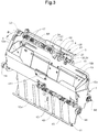
- the device 101 includes a plurality of receiving pockets 102 each having a leading pocket wall 110a and a trailing pocket wall 110b, which form a receptacle 109.
- the receiving pockets 102 are radially aligned and have radially outwardly directed pocket openings 113.
- the receiving pockets 102 are moved in the direction of movement B along a curved convex trajectory.
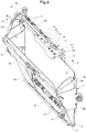
- the receiving pocket 2 contains a leading in the direction of movement B pocket wall 10a and a trailing pocket wall 10b, which limit a receiving tray 9.
- the receiving pocket 2 further includes an opposite the two pocket walls 10a, 10b adjustable pocket bottom 11th
- the insertion depth can be changed and adapted to the different product formats. This is done via an adjustment.
- the adjusting device is based on a two-part, trailing pocket wall 10b.
- the Boden maybertige wall portion on which the bottom of the bag 11 is arranged is attached via a slot guide on the second, opening-side wall part.
- the Bodenicartige wall part and with this the bottom of the bag 11 is on the slot guide relative to the opening side wall portion to the pocket opening 13 toward or away from this displaced, so that the insertion depth can be adjusted.
- the rotary rod 16 cooperates with a return spring 24 which is a torsion spring designed as a helical spring.
- the return spring 24 is arranged around the rotary rod 16 and exerts on the rotary rod 16 and thus on the clamping legs 15 a restoring force in the form of a torque.
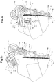
- the separating mechanism according to the first embodiment according to FIGS. 2 to 6 comprises a swivel module 20 with a swivel body 21 and a contact body 22.
- Pneumatic lines 19 in the form of vacuum lines for pneumatic devices 28 and for a first vacuum element 26 are guided to the swivel body 21 out.
- the pivoting body 21 is pivotally mounted about a positioning pivot axis S1.
- two pivot bushings 23 are arranged on the swivel body 21, via which the swivel module 20 is mounted on a rotary rod 16.
- the pivot bushes 23 are guided on the rotating rod 16.
- the swivel module 20 is rotatably mounted on the pivot rod 16 via the pivot bushes 23.
- the swivel module is coupled to a control member which cooperates with a stationary control link (not shown).
- the control element comprises a first control roller 25 which is arranged outside the positioning pivot axis S1 and which is guided along the control link.
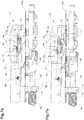
- the induced draft in the pneumatic elements 28 is reduced or adjusted.
- the bellows hollow bodies 29 expand due to the increase in pressure along their longitudinal axis L, as a result of which the contact body 22 is moved into a contact position in a linear movement toward the leading product part 6a (see FIG FIG. 5e and 6a ).
- the swivel module 20 is now pivoted back on the gate-controlled first control roller 25 back from the separating position in the passive position outside the receiving pocket 2 (see FIG. 5h ).
- the swivel body 71 comprises two pivot bushes 73, which are guided on the rotary rod 66.
- the swivel module 70 and the swivel body 71 is rotatably mounted on the pivot rod 66 via the swivel bushes 73.
- the pivot module 70 acts together with a restoring spring 74 which is a torsion spring designed as a helical spring.
- the return spring 74 is arranged about the rotary rod 66 and exerts on the swivel body 70 a restoring force in the form of a torque.
- the restoring force of the return spring 74 acts on a provision of the pivot module 70 either in its passive position or in its separating position.
- a change in position of the control roller relative to the receiving pocket by the control link causes a rotation of the pivot module 70 either in the direction or against the restoring force.
- the swivel module 70 can thus be controlled via the gate-guided control roller controlled between a passive position and a separating position.
- leading product part 6a is separated from the trailing product part.
- clamping leg 65 of the clamping device 54 is pivoted by an actuation of the second control roller via a control link (not shown) in a clamping position.
- the rotary rod 66 is rotated, so that the clamping leg is pivoted in the receiving compartment between the two product parts to the trailing product part.
- the clamping leg 65 clamps the subsequent product part to the trailing pocket wall.
- the printed product 5 can now be completely opened, for example by pivoting the receiving pocket about a pocket pivot axis by means of gravity.
- the pivot module 20, 70 does not have to be activated and remains in its passive position. It is only the clamping device actuated by the pivoted into the receptacle clamping leg 15 analogous to the example according to FIG. 1 without preceding separation of the product parts 6a, 6b, the trailing product part 6b is clamped at its prefold on the trailing pocket wall 10b.
Landscapes
- Engineering & Computer Science (AREA)
- Mechanical Engineering (AREA)
- Feeding Of Articles By Means Other Than Belts Or Rollers (AREA)
Claims (15)
- Ensemble de séparation de parties (6a, 6b) d'un produit plat (5) en plusieurs parties, l'ensemble contenant au moins une unité de réception (2, 52) qui forme un compartiment de réception (9, 59) qui reçoit le produit (5) et au moins un mécanisme de séparation (3, 53) qui sépare deux parties (6a, 6b) de produit, le mécanisme de séparation (3, 53) contenant un module pivotant (20, 70) apte à pivoter autour d'un axe (S1) de pivotement de positionnement vers et dans le compartiment de réception (9, 59) en direction du produit (5) et hors du compartiment de réception (9, 59), et présentant au moins un organe de dépression (26, 76) doté d'un élément aspirant (27, 77) qui établit un contact temporaire aspirant avec une première partie (6a) de produit,
le module pivotant (20, 70) contenant un corps pivotant (21, 71) monté à pivotement autour de l'axe (S1) de pivotement de positionnement et le module pivotant (20, 70) contenant un corps de placement (22, 72) fixé sur le corps pivotant (21, 71),
caractérisé en ce queau moins un organe de dépression (26, 76) est disposé avec son élément aspirant (27, 77) sur le corps de placement (22, 72),en ce que le corps de placement (22, 72) peut se déplacer par rapport au corps pivotant (21, 71),en ce que le module pivotant (20, 70) contient au moins un organe pneumatique (28, 78) qui coopère avec le corps de placement (22, 72) et est conçu pour déplacer le corps de placement (22, 72) par rapport au corps pivotant (21, 71). - Ensemble selon la revendication 1, caractérisé en ce que l'organe pneumatique (28, 78) contient un élément pneumatique (29, 79) qui présente dans la direction d'un axe longitudinal (L) une extension qui varie en fonction de la pression de gaz qui règne dans l'élément pneumatique (29, 79).
- Ensemble selon les revendications 1 ou 2, caractérisé en ce que le module pivotant (20) est conçu pour déplacer le corps de placement (22) au moyen de l'organe pneumatique (28) dans un déplacement linéaire par rapport au corps pivotant (21) en direction du produit (5) et/ou pour l'éloigner de ce dernier.
- Ensemble selon l'une des revendications 1 à 3, caractérisé en ce que le corps de placement (72) est fixé sur le corps pivotant (71) à pivotement autour d'un axe (S3) de pivotement de placement et en ce que le module pivotant (70) est conçu pour déplacer le corps de placement (72) au moyen de l'organe pneumatique (78) par rapport à un corps pivotant (71), en direction du produit (5) et pour l'éloigner de ce dernier.
- Ensemble selon l'une des revendications 1 à 4, caractérisé en ce que le module pivotant (20, 70) est fixé sur l'unité de réception (2, 52) de manière à pivoter autour de l'axe (S1) de pivotement de positionnement.
- Ensemble selon l'une des revendications 1 à 5, caractérisé en ce que le compartiment de réception (9, 59) est délimité par une première et une deuxième structure de soutien (10a, 10b; 60a, 60b) disposées à distance mutuelle.
- Ensemble selon la revendication 6, caractérisé en ce que le mécanisme de séparation (3, 53) contient un autre organe de dépression (30, 80) doté d'un élément aspirant (31, 81) conçu pour maintenir une deuxième partie (6b) du produit contre la deuxième structure de soutien (10a, 10b; 60a, 60b) au moyen d'un contact aspirant.
- Ensemble selon l'une des revendications 1 à 7, caractérisé en ce que l'ensemble contient un dispositif d'engagement (4, 54) doté d'un élément d'engagement (15, 65) qui peut être déplacé entre deux parties (6a, 6b) de produit séparées en vue de maintenir la séparation des parties (6a, 6b) de produit.
- Ensemble selon la revendication 8, caractérisé en ce que le dispositif d'engagement (4, 54) est un dispositif de serrage et l'élément d'engagement (15, 65) un élément de serrage qui maintient par serrage une partie (6b) de produit sur l'unité de réception (2, 52) .
- Ensemble selon l'une des revendications 1 à 9, caractérisé en ce que la ou les unité de réception (2, 52) peuvent être déplacées sur une piste de déplacement en boucle fermée.
- Ensemble selon la revendication 10, caractérisé en ce que le module pivotant (20, 70) est associé à la ou aux unités de réception (2, 52) et peut être déplacé de manière synchronisée par rapport à l'unité de réception (2, 52) sur une piste de déplacement fermée.
- Ensemble selon l'une des revendications 1 à 11, caractérisé en ce que l'ensemble contient un cercle apte à tourner autour d'au moins un axe de rotation et sur lequel les unités de réception (2, 52) sont disposées de manière à pouvoir se déplacer en boucle fermée.
- Unité de réception (2, 52) pour un ensemble de séparation de parties (6a, 6b) d'un produit plat (5) en plusieurs parties selon l'une des revendications 1 à 12, l'unité de réception (2, 52) formant un compartiment de réception (9, 59) qui reçoit le produit (5) et l'unité de réception (2, 52) contenant au moins un mécanisme de séparation (3, 53) qui sépare deux parties (6a, 6b) de produit, le mécanisme de séparation (3, 53) contenant un module pivotant (20, 70) apte à pivoter autour d'un axe (S1) de pivotement de positionnement vers et dans le compartiment de réception (9, 59) en direction du produit (5) et hors du compartiment de réception (9, 59), le module pivotant (20, 70) présentant au moins un organe de dépression (26, 76) doté d'un élément aspirant (27, 77) qui établit un contact temporaire aspirant avec une première partie (6a) de produit,
caractérisé en ce quele module pivotant (20, 70) contient un corps pivotant (21, 71) monté à pivotement autour de l'axe (S1) de pivotement de positionnement et le module pivotant (20, 70) contient un corps de placement (22, 72) fixé sur le corps pivotant (21, 71),en ce que le ou les organes de dépression (26, 76) sont disposés avec leur élément aspirant (27, 77) sur le corps de placement (22, 72),en ce que le corps de placement (22, 72) peut se déplacer par rapport au corps pivotant (21, 71),en ce que le module pivotant (20, 70) contient au moins un organe pneumatique (28, 78) qui coopère avec le corps de placement (22, 72) et est conçu pour déplacer le corps de placement (22, 72) par rapport au corps pivotant (21, 71). - Procédé de séparation de deux parties (6a, 6b) d'un produit plat (5) en plusieurs pièces au moyen de l'ensemble selon l'une des revendications 1 à 12, le procédé étant caractérisé par les étapes suivantes :introduction d'un produit (5) dans le compartiment de réception (9, 59) de la unité de réception (2, 52),pivotement du module pivotant (20, 70) autour de l'axe (S1) de pivotement de positionnement dans le compartiment de réception (9, 59) en direction du produit (5),déplacement du corps de placement (22, 72) par rapport au corps pivotant (21, 71) en direction du produit (5),formation d'un contact aspirant entre l'élément aspirant (27, 77) du organe de dépression (26, 76) et d'une première partie (6a) de produit tournée vers l'élément aspirant (27, 77) au moyen d'une dépression,renvoi du corps de placement (22, 72) vers le corps pivotant (21, 71) et de ce fait séparation de la première partie (6a) de produit de la deuxième partie (6b) de produit,introduction d'un élément d'engagement (15, 65) entre les deux parties (6a, 6b) de produit,libération du contact aspirant entre l'élément aspirant (27, 77) et la partie (6a) de produit tournée vers ce dernier etpivotement du module pivotant (20, 70) hors du compartiment de réception (9, 59) autour de l'axe (S1) de pivotement de positionnement.
- Procédé selon la revendication 14, caractérisé en ce que la deuxième partie (6b) de produit qui repose contre la deuxième structure de soutien (10a, 10b; 60a, 60b) est maintenue après l'insertion du produit (5) dans le compartiment de réception (9, 59) au moyen d'un contact aspirant réalisé à l'aide d'un élément aspirant (31, 81) d'un autre organe de dépression (30, 80) contre la deuxième structure de soutien (10a, 10b; 60a, 60b) .
Applications Claiming Priority (2)
| Application Number | Priority Date | Filing Date | Title |
|---|---|---|---|
| CH01456/14A CH710151A1 (de) | 2014-09-25 | 2014-09-25 | Vorrichtung und Verfahren zum Separieren von Produktteilen eines mehrteiligen Produktes. |
| PCT/CH2015/000141 WO2016044959A1 (fr) | 2014-09-25 | 2015-09-21 | Dispositif et procédé de séparation de parties d'un produit à plusieurs parties |
Publications (2)
| Publication Number | Publication Date |
|---|---|
| EP3197801A1 EP3197801A1 (fr) | 2017-08-02 |
| EP3197801B1 true EP3197801B1 (fr) | 2018-12-12 |
Family
ID=54251893
Family Applications (1)
| Application Number | Title | Priority Date | Filing Date |
|---|---|---|---|
| EP15775070.4A Not-in-force EP3197801B1 (fr) | 2014-09-25 | 2015-09-21 | Dispositif et procédé de séparation de parties d'un produit à plusieurs parties |
Country Status (3)
| Country | Link |
|---|---|
| EP (1) | EP3197801B1 (fr) |
| CH (1) | CH710151A1 (fr) |
| WO (1) | WO2016044959A1 (fr) |
Family Cites Families (7)
| Publication number | Priority date | Publication date | Assignee | Title |
|---|---|---|---|---|
| GB613271A (en) * | 1945-04-02 | 1948-11-24 | Tw & Cb Sheridan Co | Machines for stuffing newspapers or similar sheet material assemblages |
| US5052168A (en) * | 1990-02-05 | 1991-10-01 | Opex Corporation | Method and apparatus for spreading open envelopes |
| EP0721903B1 (fr) * | 1995-01-13 | 1998-08-12 | Ferag AG | Dispositif pour ouvrir des produits imprimés et appareil pour traiter des produits imprimés |
| EP1310444B1 (fr) * | 2001-11-08 | 2005-07-20 | Grapha-Holding AG | Dispositif d'assemblage par insertion de produits imprimés |
| CA2630138C (fr) * | 2007-05-16 | 2015-12-01 | Ferag Ag | Methode et dispositif pour ouvrir des produits imprimes |
| US8191883B2 (en) * | 2008-04-01 | 2012-06-05 | Muller Martini Corp. | Pocket management system |
| CH706457A1 (de) * | 2012-04-30 | 2013-10-31 | Ferag Ag | Verfahren und Vorrichtung zum Einstecken von Gegenständen in gefalzte Druckereiprodukte. |
-
2014
- 2014-09-25 CH CH01456/14A patent/CH710151A1/de not_active Application Discontinuation
-
2015
- 2015-09-21 EP EP15775070.4A patent/EP3197801B1/fr not_active Not-in-force
- 2015-09-21 WO PCT/CH2015/000141 patent/WO2016044959A1/fr active Application Filing
Non-Patent Citations (1)
| Title |
|---|
| None * |
Also Published As
| Publication number | Publication date |
|---|---|
| EP3197801A1 (fr) | 2017-08-02 |
| CH710151A1 (de) | 2016-03-31 |
| WO2016044959A1 (fr) | 2016-03-31 |
Similar Documents
| Publication | Publication Date | Title |
|---|---|---|
| DE3047436C2 (fr) | ||
| EP2700599B1 (fr) | Dispositif et méthode de séparation d'objets plats pliables individuels de la face inférieure d'une pile | |
| EP2502862A1 (fr) | Procédé et dispositif de traitement de feuilles de différents formats | |
| EP0931747B1 (fr) | Plieuse pour machine rotative à imprimer | |
| EP0897890B1 (fr) | Procédé et dispositif pour produire un courant de produits tournés avec une pince de préhension de coin | |
| DE102004004893B3 (de) | Kuvertwendestation | |
| EP2035308A1 (fr) | Dispositif pour séparer différents objets plats d'une pile et pour évacuer les objets séparés | |
| EP0712736B1 (fr) | Méthode pour la fabrication de livres, brochures ou similaires reliés par adhésif | |
| EP2297014B1 (fr) | Dispositif d'insertion et procédé d'insertion | |
| EP0681979B1 (fr) | Dispositif pour traiter des produits imprimés | |
| EP1351873A1 (fr) | Procede de traitement de produits d'imprimerie | |
| EP1528023B1 (fr) | Méthode et dispositif pour changer un flux d'articles plats | |
| EP0970820B1 (fr) | Dispositif de transport | |
| EP3197801B1 (fr) | Dispositif et procédé de séparation de parties d'un produit à plusieurs parties | |
| DE3427570A1 (de) | Vorrichtung zum falzen und weiterverarbeiten von druckexemplaren | |
| DE102007027945A1 (de) | Verfahren und Vorrichtung zur Herstellung eines gefalzten Bogens | |
| DE10336757B4 (de) | Taschenfalzverfahren | |
| EP2711164B1 (fr) | Dispositif et procédé destinés à ouvrir une zone d'extrémité d'un corps de sachet tubulaire | |
| EP1038671B1 (fr) | Dispositif de séparation des feuilles | |
| EP0699611A1 (fr) | Dispositif de transport pour l'alimentation des produits imprimés plats à une machine de traitement | |
| DE102006031983B3 (de) | Falztasche, Falzmaschine und Verfahren | |
| EP2844593B1 (fr) | Procédé et dispositif pour ouvrir des produits d'imprimerie | |
| DE19602610B4 (de) | Verfahren und Vorrichtung zur Bearbeitung von Bogenstapeln | |
| DE102005008418A1 (de) | Verfahren und Vorrichtung zum Entnehmen von Zuschnitten aus einem Magazin | |
| DE836431C (de) | Maschine zum Herstellen und Bedrucken von Flachbeuteln |
Legal Events
| Date | Code | Title | Description |
|---|---|---|---|
| STAA | Information on the status of an ep patent application or granted ep patent |
Free format text: STATUS: THE INTERNATIONAL PUBLICATION HAS BEEN MADE |
|
| PUAI | Public reference made under article 153(3) epc to a published international application that has entered the european phase |
Free format text: ORIGINAL CODE: 0009012 |
|
| STAA | Information on the status of an ep patent application or granted ep patent |
Free format text: STATUS: REQUEST FOR EXAMINATION WAS MADE |
|
| 17P | Request for examination filed |
Effective date: 20170321 |
|
| AK | Designated contracting states |
Kind code of ref document: A1 Designated state(s): AL AT BE BG CH CY CZ DE DK EE ES FI FR GB GR HR HU IE IS IT LI LT LU LV MC MK MT NL NO PL PT RO RS SE SI SK SM TR |
|
| AX | Request for extension of the european patent |
Extension state: BA ME |
|
| DAV | Request for validation of the european patent (deleted) | ||
| DAX | Request for extension of the european patent (deleted) | ||
| GRAP | Despatch of communication of intention to grant a patent |
Free format text: ORIGINAL CODE: EPIDOSNIGR1 |
|
| STAA | Information on the status of an ep patent application or granted ep patent |
Free format text: STATUS: GRANT OF PATENT IS INTENDED |
|
| INTG | Intention to grant announced |
Effective date: 20180717 |
|
| GRAS | Grant fee paid |
Free format text: ORIGINAL CODE: EPIDOSNIGR3 |
|
| GRAA | (expected) grant |
Free format text: ORIGINAL CODE: 0009210 |
|
| STAA | Information on the status of an ep patent application or granted ep patent |
Free format text: STATUS: THE PATENT HAS BEEN GRANTED |
|
| AK | Designated contracting states |
Kind code of ref document: B1 Designated state(s): AL AT BE BG CH CY CZ DE DK EE ES FI FR GB GR HR HU IE IS IT LI LT LU LV MC MK MT NL NO PL PT RO RS SE SI SK SM TR |
|
| REG | Reference to a national code |
Ref country code: GB Ref legal event code: FG4D Free format text: NOT ENGLISH |
|
| REG | Reference to a national code |
Ref country code: CH Ref legal event code: EP |
|
| REG | Reference to a national code |
Ref country code: AT Ref legal event code: REF Ref document number: 1075706 Country of ref document: AT Kind code of ref document: T Effective date: 20181215 |
|
| REG | Reference to a national code |
Ref country code: DE Ref legal event code: R096 Ref document number: 502015007229 Country of ref document: DE |
|
| REG | Reference to a national code |
Ref country code: IE Ref legal event code: FG4D Free format text: LANGUAGE OF EP DOCUMENT: GERMAN |
|
| REG | Reference to a national code |
Ref country code: CH Ref legal event code: NV Representative=s name: FREI PATENTANWALTSBUERO AG, CH |
|
| REG | Reference to a national code |
Ref country code: NL Ref legal event code: MP Effective date: 20181212 |
|
| REG | Reference to a national code |
Ref country code: LT Ref legal event code: MG4D |
|
| PG25 | Lapsed in a contracting state [announced via postgrant information from national office to epo] |
Ref country code: LV Free format text: LAPSE BECAUSE OF FAILURE TO SUBMIT A TRANSLATION OF THE DESCRIPTION OR TO PAY THE FEE WITHIN THE PRESCRIBED TIME-LIMIT Effective date: 20181212 Ref country code: NO Free format text: LAPSE BECAUSE OF FAILURE TO SUBMIT A TRANSLATION OF THE DESCRIPTION OR TO PAY THE FEE WITHIN THE PRESCRIBED TIME-LIMIT Effective date: 20190312 Ref country code: BG Free format text: LAPSE BECAUSE OF FAILURE TO SUBMIT A TRANSLATION OF THE DESCRIPTION OR TO PAY THE FEE WITHIN THE PRESCRIBED TIME-LIMIT Effective date: 20190312 Ref country code: HR Free format text: LAPSE BECAUSE OF FAILURE TO SUBMIT A TRANSLATION OF THE DESCRIPTION OR TO PAY THE FEE WITHIN THE PRESCRIBED TIME-LIMIT Effective date: 20181212 Ref country code: ES Free format text: LAPSE BECAUSE OF FAILURE TO SUBMIT A TRANSLATION OF THE DESCRIPTION OR TO PAY THE FEE WITHIN THE PRESCRIBED TIME-LIMIT Effective date: 20181212 Ref country code: LT Free format text: LAPSE BECAUSE OF FAILURE TO SUBMIT A TRANSLATION OF THE DESCRIPTION OR TO PAY THE FEE WITHIN THE PRESCRIBED TIME-LIMIT Effective date: 20181212 Ref country code: FI Free format text: LAPSE BECAUSE OF FAILURE TO SUBMIT A TRANSLATION OF THE DESCRIPTION OR TO PAY THE FEE WITHIN THE PRESCRIBED TIME-LIMIT Effective date: 20181212 |
|
| PG25 | Lapsed in a contracting state [announced via postgrant information from national office to epo] |
Ref country code: GR Free format text: LAPSE BECAUSE OF FAILURE TO SUBMIT A TRANSLATION OF THE DESCRIPTION OR TO PAY THE FEE WITHIN THE PRESCRIBED TIME-LIMIT Effective date: 20190313 Ref country code: SE Free format text: LAPSE BECAUSE OF FAILURE TO SUBMIT A TRANSLATION OF THE DESCRIPTION OR TO PAY THE FEE WITHIN THE PRESCRIBED TIME-LIMIT Effective date: 20181212 Ref country code: RS Free format text: LAPSE BECAUSE OF FAILURE TO SUBMIT A TRANSLATION OF THE DESCRIPTION OR TO PAY THE FEE WITHIN THE PRESCRIBED TIME-LIMIT Effective date: 20181212 Ref country code: AL Free format text: LAPSE BECAUSE OF FAILURE TO SUBMIT A TRANSLATION OF THE DESCRIPTION OR TO PAY THE FEE WITHIN THE PRESCRIBED TIME-LIMIT Effective date: 20181212 |
|
| PG25 | Lapsed in a contracting state [announced via postgrant information from national office to epo] |
Ref country code: NL Free format text: LAPSE BECAUSE OF FAILURE TO SUBMIT A TRANSLATION OF THE DESCRIPTION OR TO PAY THE FEE WITHIN THE PRESCRIBED TIME-LIMIT Effective date: 20181212 |
|
| PG25 | Lapsed in a contracting state [announced via postgrant information from national office to epo] |
Ref country code: IT Free format text: LAPSE BECAUSE OF FAILURE TO SUBMIT A TRANSLATION OF THE DESCRIPTION OR TO PAY THE FEE WITHIN THE PRESCRIBED TIME-LIMIT Effective date: 20181212 Ref country code: CZ Free format text: LAPSE BECAUSE OF FAILURE TO SUBMIT A TRANSLATION OF THE DESCRIPTION OR TO PAY THE FEE WITHIN THE PRESCRIBED TIME-LIMIT Effective date: 20181212 Ref country code: PT Free format text: LAPSE BECAUSE OF FAILURE TO SUBMIT A TRANSLATION OF THE DESCRIPTION OR TO PAY THE FEE WITHIN THE PRESCRIBED TIME-LIMIT Effective date: 20190412 Ref country code: PL Free format text: LAPSE BECAUSE OF FAILURE TO SUBMIT A TRANSLATION OF THE DESCRIPTION OR TO PAY THE FEE WITHIN THE PRESCRIBED TIME-LIMIT Effective date: 20181212 |
|
| PG25 | Lapsed in a contracting state [announced via postgrant information from national office to epo] |
Ref country code: RO Free format text: LAPSE BECAUSE OF FAILURE TO SUBMIT A TRANSLATION OF THE DESCRIPTION OR TO PAY THE FEE WITHIN THE PRESCRIBED TIME-LIMIT Effective date: 20181212 Ref country code: IS Free format text: LAPSE BECAUSE OF FAILURE TO SUBMIT A TRANSLATION OF THE DESCRIPTION OR TO PAY THE FEE WITHIN THE PRESCRIBED TIME-LIMIT Effective date: 20190412 Ref country code: SK Free format text: LAPSE BECAUSE OF FAILURE TO SUBMIT A TRANSLATION OF THE DESCRIPTION OR TO PAY THE FEE WITHIN THE PRESCRIBED TIME-LIMIT Effective date: 20181212 Ref country code: EE Free format text: LAPSE BECAUSE OF FAILURE TO SUBMIT A TRANSLATION OF THE DESCRIPTION OR TO PAY THE FEE WITHIN THE PRESCRIBED TIME-LIMIT Effective date: 20181212 Ref country code: SM Free format text: LAPSE BECAUSE OF FAILURE TO SUBMIT A TRANSLATION OF THE DESCRIPTION OR TO PAY THE FEE WITHIN THE PRESCRIBED TIME-LIMIT Effective date: 20181212 |
|
| REG | Reference to a national code |
Ref country code: DE Ref legal event code: R097 Ref document number: 502015007229 Country of ref document: DE |
|
| PLBE | No opposition filed within time limit |
Free format text: ORIGINAL CODE: 0009261 |
|
| STAA | Information on the status of an ep patent application or granted ep patent |
Free format text: STATUS: NO OPPOSITION FILED WITHIN TIME LIMIT |
|
| PG25 | Lapsed in a contracting state [announced via postgrant information from national office to epo] |
Ref country code: SI Free format text: LAPSE BECAUSE OF FAILURE TO SUBMIT A TRANSLATION OF THE DESCRIPTION OR TO PAY THE FEE WITHIN THE PRESCRIBED TIME-LIMIT Effective date: 20181212 Ref country code: DK Free format text: LAPSE BECAUSE OF FAILURE TO SUBMIT A TRANSLATION OF THE DESCRIPTION OR TO PAY THE FEE WITHIN THE PRESCRIBED TIME-LIMIT Effective date: 20181212 |
|
| 26N | No opposition filed |
Effective date: 20190913 |
|
| PG25 | Lapsed in a contracting state [announced via postgrant information from national office to epo] |
Ref country code: TR Free format text: LAPSE BECAUSE OF FAILURE TO SUBMIT A TRANSLATION OF THE DESCRIPTION OR TO PAY THE FEE WITHIN THE PRESCRIBED TIME-LIMIT Effective date: 20181212 |
|
| REG | Reference to a national code |
Ref country code: DE Ref legal event code: R119 Ref document number: 502015007229 Country of ref document: DE |
|
| PG25 | Lapsed in a contracting state [announced via postgrant information from national office to epo] |
Ref country code: MC Free format text: LAPSE BECAUSE OF FAILURE TO SUBMIT A TRANSLATION OF THE DESCRIPTION OR TO PAY THE FEE WITHIN THE PRESCRIBED TIME-LIMIT Effective date: 20181212 |
|
| REG | Reference to a national code |
Ref country code: CH Ref legal event code: PL |
|
| PG25 | Lapsed in a contracting state [announced via postgrant information from national office to epo] |
Ref country code: LI Free format text: LAPSE BECAUSE OF NON-PAYMENT OF DUE FEES Effective date: 20190930 Ref country code: IE Free format text: LAPSE BECAUSE OF NON-PAYMENT OF DUE FEES Effective date: 20190921 Ref country code: CH Free format text: LAPSE BECAUSE OF NON-PAYMENT OF DUE FEES Effective date: 20190930 Ref country code: DE Free format text: LAPSE BECAUSE OF NON-PAYMENT OF DUE FEES Effective date: 20200401 Ref country code: LU Free format text: LAPSE BECAUSE OF NON-PAYMENT OF DUE FEES Effective date: 20190921 |
|
| REG | Reference to a national code |
Ref country code: BE Ref legal event code: MM Effective date: 20190930 |
|
| PG25 | Lapsed in a contracting state [announced via postgrant information from national office to epo] |
Ref country code: BE Free format text: LAPSE BECAUSE OF NON-PAYMENT OF DUE FEES Effective date: 20190930 |
|
| GBPC | Gb: european patent ceased through non-payment of renewal fee |
Effective date: 20190921 |
|
| PG25 | Lapsed in a contracting state [announced via postgrant information from national office to epo] |
Ref country code: FR Free format text: LAPSE BECAUSE OF NON-PAYMENT OF DUE FEES Effective date: 20190930 Ref country code: GB Free format text: LAPSE BECAUSE OF NON-PAYMENT OF DUE FEES Effective date: 20190921 |
|
| PG25 | Lapsed in a contracting state [announced via postgrant information from national office to epo] |
Ref country code: CY Free format text: LAPSE BECAUSE OF FAILURE TO SUBMIT A TRANSLATION OF THE DESCRIPTION OR TO PAY THE FEE WITHIN THE PRESCRIBED TIME-LIMIT Effective date: 20181212 |
|
| PG25 | Lapsed in a contracting state [announced via postgrant information from national office to epo] |
Ref country code: HU Free format text: LAPSE BECAUSE OF FAILURE TO SUBMIT A TRANSLATION OF THE DESCRIPTION OR TO PAY THE FEE WITHIN THE PRESCRIBED TIME-LIMIT; INVALID AB INITIO Effective date: 20150921 Ref country code: MT Free format text: LAPSE BECAUSE OF FAILURE TO SUBMIT A TRANSLATION OF THE DESCRIPTION OR TO PAY THE FEE WITHIN THE PRESCRIBED TIME-LIMIT Effective date: 20181212 |
|
| REG | Reference to a national code |
Ref country code: AT Ref legal event code: MM01 Ref document number: 1075706 Country of ref document: AT Kind code of ref document: T Effective date: 20200921 |
|
| PG25 | Lapsed in a contracting state [announced via postgrant information from national office to epo] |
Ref country code: AT Free format text: LAPSE BECAUSE OF NON-PAYMENT OF DUE FEES Effective date: 20200921 |
|
| PG25 | Lapsed in a contracting state [announced via postgrant information from national office to epo] |
Ref country code: MK Free format text: LAPSE BECAUSE OF FAILURE TO SUBMIT A TRANSLATION OF THE DESCRIPTION OR TO PAY THE FEE WITHIN THE PRESCRIBED TIME-LIMIT Effective date: 20181212 |