EP3197801B1 - Apparatus and method for separating product parts of a multipart product - Google Patents
Apparatus and method for separating product parts of a multipart product Download PDFInfo
- Publication number
- EP3197801B1 EP3197801B1 EP15775070.4A EP15775070A EP3197801B1 EP 3197801 B1 EP3197801 B1 EP 3197801B1 EP 15775070 A EP15775070 A EP 15775070A EP 3197801 B1 EP3197801 B1 EP 3197801B1
- Authority
- EP
- European Patent Office
- Prior art keywords
- product
- pivoting
- suction
- receiving
- module
- Prior art date
- Legal status (The legal status is an assumption and is not a legal conclusion. Google has not performed a legal analysis and makes no representation as to the accuracy of the status listed.)
- Not-in-force
Links
Images


Classifications
-
- B—PERFORMING OPERATIONS; TRANSPORTING
- B65—CONVEYING; PACKING; STORING; HANDLING THIN OR FILAMENTARY MATERIAL
- B65H—HANDLING THIN OR FILAMENTARY MATERIAL, e.g. SHEETS, WEBS, CABLES
- B65H5/00—Feeding articles separated from piles; Feeding articles to machines
- B65H5/30—Opening devices for folded sheets or signatures
- B65H5/305—Opening devices for folded sheets or signatures comprising rotary means for opening the folded sheets
-
- B—PERFORMING OPERATIONS; TRANSPORTING
- B65—CONVEYING; PACKING; STORING; HANDLING THIN OR FILAMENTARY MATERIAL
- B65H—HANDLING THIN OR FILAMENTARY MATERIAL, e.g. SHEETS, WEBS, CABLES
- B65H39/00—Associating, collating, or gathering articles or webs
- B65H39/02—Associating,collating or gathering articles from several sources
- B65H39/04—Associating,collating or gathering articles from several sources from piles
- B65H39/045—Associating,collating or gathering articles from several sources from piles by collecting in rotary carriers
-
- B—PERFORMING OPERATIONS; TRANSPORTING
- B65—CONVEYING; PACKING; STORING; HANDLING THIN OR FILAMENTARY MATERIAL
- B65H—HANDLING THIN OR FILAMENTARY MATERIAL, e.g. SHEETS, WEBS, CABLES
- B65H39/00—Associating, collating, or gathering articles or webs
- B65H39/02—Associating,collating or gathering articles from several sources
- B65H39/06—Associating,collating or gathering articles from several sources from delivery streams
- B65H39/065—Associating,collating or gathering articles from several sources from delivery streams by collecting in rotary carriers
-
- B—PERFORMING OPERATIONS; TRANSPORTING
- B65—CONVEYING; PACKING; STORING; HANDLING THIN OR FILAMENTARY MATERIAL
- B65H—HANDLING THIN OR FILAMENTARY MATERIAL, e.g. SHEETS, WEBS, CABLES
- B65H2301/00—Handling processes for sheets or webs
- B65H2301/40—Type of handling process
- B65H2301/43—Gathering; Associating; Assembling
- B65H2301/431—Features with regard to the collection, nature, sequence and/or the making thereof
- B65H2301/4317—Signatures, i.e. involving folded main product or jacket
- B65H2301/43171—Inserting subproducts in a signature as main product
- B65H2301/431711—Inserting subproducts in a signature as main product the subproduct being inserted in a direction substantially perpendicular to the fold of the main product
- B65H2301/431716—Inserting subproducts in a signature as main product the subproduct being inserted in a direction substantially perpendicular to the fold of the main product the main product being oriented with opening face upwards
-
- B—PERFORMING OPERATIONS; TRANSPORTING
- B65—CONVEYING; PACKING; STORING; HANDLING THIN OR FILAMENTARY MATERIAL
- B65H—HANDLING THIN OR FILAMENTARY MATERIAL, e.g. SHEETS, WEBS, CABLES
- B65H2406/00—Means using fluid
- B65H2406/30—Suction means
- B65H2406/34—Suction grippers
- B65H2406/341—Suction grippers being oscillated in arcuate paths
Definitions
- the prefold can be z.
- an asymmetric, i. outside center produce arranged folds.
- printed products without a prefold are usually folded in the middle or cut after folding.
- the product can also form between the folded edge and the free edge also each have a lateral, free edge. However, it is also possible that the product forms a lateral free edge between the folded edge and the free edge on one side and a lateral folded edge on the opposite side. Such Zweifalz excursion can be opened by means of a Vorfalzes.
- the products can z. B. be folded once. Each product part can be formed einblättrig in this case.
- the products may be, for example, envelopes or folded sheets.
- the receiving unit may be a receiving compartment or a receiving bag.
- the receiving unit can also be present as a receiving channel.
- the receptacle corresponds to a receiving space for the product.
- the contact body can be moved toward and away from the product in the receiving compartment or to a second support structure via the at least one pneumatic element relative to the swivel body.
- the swivel module is connected to at least one swivel bush, which is guided on an axle element, such as axle rod or axle rod.
- axle element such as axle rod or axle rod.
- rod should generally also include the term “rod”.
- the swivel module may be coupled to a control member which cooperates with a particular stationary control link.
- the control member may include a control roller disposed outside the positioning pivot axis of the pivot module, which control roller is guidable along the control link.
- the device contains according to an embodiment of the invention, an engagement with an engaging element.
- the engagement element is movable between the two separated product parts for the purpose of maintaining the separation of the product parts.
- the engagement member is movable between the product parts to prevent re-merging of the product parts.
- the engagement means may further cooperate with a return member which exerts a restoring force on the engagement member.
- the restoring force acts on a provision of the engagement element either in its engagement position between the product parts or in a passive position outside the product parts.
- the return member may be designed as a torsion spring coil spring.
- the torsion spring may be arranged on the rotary rod.
- the first support structure in particular a leading support structure.
- the second support structure is in particular a trailing support structure.
- the first product part faces the leading support structure as a leading product part.
- the second product part faces the trailing support structure as a trailing product part.
- leading and trailing refer in the present patent application to the direction of movement of the receiving unit or conveying direction of Products along the path of motion, as will be described in more detail below.
- the pneumatic lines can be guided by the vacuum element or the pneumatic element to the axis of rotation of the concentricity, which is designed as a hollow shaft.
- the pneumatic lines can be used together with a guided in the hollow shaft central supply line with negative pressure, i. with a suction, be acted upon.
- the central feed line is connected to a vacuum generating device.
- the receiving units are arranged, for example, radially around the axis of rotation with radially outwardly facing receiving openings on the concentricity.
- the receiving units can be mounted pivotably via a receiving pivot axis relative to the concentricity.
- the device may in particular be a plug-in device which is designed for opening the products and for inserting inserts between the product parts of opened products.
- the invention also relates to a receiving unit for a device described above for separating product parts of a multi-part, flat product.
- the release of the suction contact is done in particular in the waiting position.
- the pivoting back of the swivel module about the positioning pivot axis out of the receiving compartment from the separating position into the passive position occurs in particular only after release of the suction contact.
- Separiermodul formed as part of the receiving unit they are moved together along the path of movement. This allows the implementation of the method according to the invention during the movement of the receiving unit along its path of movement and, correspondingly, during the conveyance of the products along its conveying path.
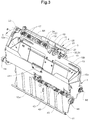
- the device 101 includes a plurality of receiving pockets 102 each having a leading pocket wall 110a and a trailing pocket wall 110b, which form a receptacle 109.
- the receiving pockets 102 are radially aligned and have radially outwardly directed pocket openings 113.
- the receiving pockets 102 are moved in the direction of movement B along a curved convex trajectory.
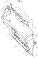
- the receiving pocket 2 contains a leading in the direction of movement B pocket wall 10a and a trailing pocket wall 10b, which limit a receiving tray 9.
- the receiving pocket 2 further includes an opposite the two pocket walls 10a, 10b adjustable pocket bottom 11th
- the insertion depth can be changed and adapted to the different product formats. This is done via an adjustment.
- the adjusting device is based on a two-part, trailing pocket wall 10b.
- the Boden maybertige wall portion on which the bottom of the bag 11 is arranged is attached via a slot guide on the second, opening-side wall part.
- the Bodenicartige wall part and with this the bottom of the bag 11 is on the slot guide relative to the opening side wall portion to the pocket opening 13 toward or away from this displaced, so that the insertion depth can be adjusted.
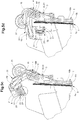
- the rotary rod 16 cooperates with a return spring 24 which is a torsion spring designed as a helical spring.
- the return spring 24 is arranged around the rotary rod 16 and exerts on the rotary rod 16 and thus on the clamping legs 15 a restoring force in the form of a torque.
- the separating mechanism according to the first embodiment according to FIGS. 2 to 6 comprises a swivel module 20 with a swivel body 21 and a contact body 22.
- Pneumatic lines 19 in the form of vacuum lines for pneumatic devices 28 and for a first vacuum element 26 are guided to the swivel body 21 out.
- the pivoting body 21 is pivotally mounted about a positioning pivot axis S1.
- two pivot bushings 23 are arranged on the swivel body 21, via which the swivel module 20 is mounted on a rotary rod 16.
- the pivot bushes 23 are guided on the rotating rod 16.
- the swivel module 20 is rotatably mounted on the pivot rod 16 via the pivot bushes 23.
- the swivel module is coupled to a control member which cooperates with a stationary control link (not shown).
- the control element comprises a first control roller 25 which is arranged outside the positioning pivot axis S1 and which is guided along the control link.
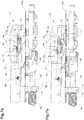
- the induced draft in the pneumatic elements 28 is reduced or adjusted.
- the bellows hollow bodies 29 expand due to the increase in pressure along their longitudinal axis L, as a result of which the contact body 22 is moved into a contact position in a linear movement toward the leading product part 6a (see FIG FIG. 5e and 6a ).
- the swivel module 20 is now pivoted back on the gate-controlled first control roller 25 back from the separating position in the passive position outside the receiving pocket 2 (see FIG. 5h ).
- the swivel body 71 comprises two pivot bushes 73, which are guided on the rotary rod 66.
- the swivel module 70 and the swivel body 71 is rotatably mounted on the pivot rod 66 via the swivel bushes 73.
- the pivot module 70 acts together with a restoring spring 74 which is a torsion spring designed as a helical spring.
- the return spring 74 is arranged about the rotary rod 66 and exerts on the swivel body 70 a restoring force in the form of a torque.
- the restoring force of the return spring 74 acts on a provision of the pivot module 70 either in its passive position or in its separating position.
- a change in position of the control roller relative to the receiving pocket by the control link causes a rotation of the pivot module 70 either in the direction or against the restoring force.
- the swivel module 70 can thus be controlled via the gate-guided control roller controlled between a passive position and a separating position.
- leading product part 6a is separated from the trailing product part.
- clamping leg 65 of the clamping device 54 is pivoted by an actuation of the second control roller via a control link (not shown) in a clamping position.
- the rotary rod 66 is rotated, so that the clamping leg is pivoted in the receiving compartment between the two product parts to the trailing product part.
- the clamping leg 65 clamps the subsequent product part to the trailing pocket wall.
- the printed product 5 can now be completely opened, for example by pivoting the receiving pocket about a pocket pivot axis by means of gravity.
- the pivot module 20, 70 does not have to be activated and remains in its passive position. It is only the clamping device actuated by the pivoted into the receptacle clamping leg 15 analogous to the example according to FIG. 1 without preceding separation of the product parts 6a, 6b, the trailing product part 6b is clamped at its prefold on the trailing pocket wall 10b.
Description
Die Erfindung liegt auf dem Gebiet der Förderung und Weiterverarbeitung von flächigen Produkten, insbesondere Druckprodukten. Die Erfindung betrifft eine Vorrichtung zum Separieren von Produktteilen eines mehrteiligen, flächigen Produktes, enthaltend mindestens eine Aufnahmeeinheit, welche ein Aufnahmefach zur Aufnahme des Produktes ausbildet, und mindestens einen Separiermechanismus zum Separieren zweier Produktteile, wobei der Separiermechanismus ein um eine Positionierschwenkachse in das Aufnahmefach zum Produkt im Aufnahmefach hin und wieder aus dem Aufnahmefach heraus schwenkbares Schwenkmodul mit mindestens einem Unterdruckorgan mit einem saugwirksamen Element zur Herstellung eines temporären Saugkontaktes mit einem ersten Produktteil enthält.The invention is in the field of promotion and further processing of sheet products, especially printed products. The invention relates to a device for separating product parts of a multi-part, flat product, comprising at least one receiving unit, which forms a receptacle for receiving the product, and at least one separating mechanism for separating two product parts, wherein the separating mechanism to a product about a positioning pivot axis in the receiving compartment in the receiving compartment from time to time from the receiving compartment out pivoting swivel module with at least one vacuum element with a suction-active element for producing a temporary suction contact with a first product part contains.
Die Erfindung betrifft auch ein Verfahren zum Separieren der Produktteile eines mehrteiligen, flächigen Produktes unter Verwendung der erfindungsgemässen Vorrichtung.The invention also relates to a method for separating the product parts of a multi-part, flat product using the device according to the invention.
Gefalzte Druckprodukte zeichnen sich durch eine Falzkante aus, entlang welcher das Druckprodukt gefalzt ist und einen ersten und zweiten Produktteil ausbildet. Der Falzkante gegenüber sind die freien Kanten der Produktteile angeordnet.Folded printed products are characterized by a folded edge, along which the printed product is folded and forms a first and second product part. The folded edge opposite the free edges of the product parts are arranged.
Gefalzte Druckprodukte müssen im Laufe ihrer Weiterverarbeitung in der Regel mindestens einmal geöffnet werden, um zwischen ihre Produktteile weitere Druckprodukte, wie Zeitungsteile, Prospekte, Broschüren, Flyer, Warenproben oder sonstige weitere, in der Regel flächige Beilagen einzustecken.Folded printed products usually have to be opened at least once in the course of their further processing in order to produce further printed products between their product parts. such as newspapers, brochures, brochures, flyers, samples or other additional, usually flat inserts to insert.
Um das Öffnen gefalzter Produkte zu erleichtern bzw. überhaupt zu ermöglichen, ist es üblich, dass der eine Produktteil einen sogenannten Vorfalz aufweist. Der Vorfalz ist ein Flächenabschnitt an einem der Produktteile im Bereich der freien Kante, die der Falzkante gegenüber liegt. Der genannte Flächenabschnitt zeichnet sich dadurch aus, dass dieser der freien Kante des anderen Produktteils vorsteht. Der eine Produktteil bildet also gegenüber dem anderen Produktteil einen Freilegebereich aus.In order to facilitate the opening of folded products or to make it possible at all, it is customary that the one product part has a so-called pre-fold. The pre-fold is a surface portion on one of the product parts in the region of the free edge, which lies opposite the folded edge. Said surface portion is characterized in that it protrudes from the free edge of the other product part. The one product part thus forms a free area with respect to the other product part.
Der Vorfalz lässt sich z. B. durch das Anbringen eines asymmetrisch, d.h. aussenmittig, angeordneten Falzes herstellen. Entsprechend sind Druckprodukte ohne Vorfalz in der Regel mittig gefalzt oder nach dem Falzen geschnitten.The prefold can be z. By attaching an asymmetric, i. outside center, produce arranged folds. Correspondingly, printed products without a prefold are usually folded in the middle or cut after folding.
Ein solcher Vorfalz ermöglicht es beispielsweise, den einen Produktteil am Vorfalz, z. B. mittels einer Klammer oder eines Saugers, zu ergreifen bzw. zu fixieren. Die beiden Produktteile lassen sich nun zum Beispiel mit Schwerkraftunterstützung auseinander bewegen, wobei der andere Produktteil gehalten wird. Auf diese Weise lassen sich die Produktteile separieren und das Druckprodukt kann schnell und einfach geöffnet werden.Such a prefold allows, for example, the one product part at the prefold, z. B. by means of a clamp or a nipple to take or fix. The two parts of the product can now be moved apart, for example with gravity support, keeping the other part of the product. In this way, the product parts can be separated and the printed product can be opened quickly and easily.
Stellvertretend für eine Vielzahl von Patentpublikationen, welche Öffnungsvorrichtungen zum Gegenstand haben, die gemäss dem oben beschriebene Öffnungsprinzip arbeiten, sei an dieser Stelle die europäische Patentpublikation
Die
Die Abteile werden entlang einer Bogenbahn nach unten geführt, wobei die Abteilöffnungen am äusseren Umfang nach unten bewegt werden. Bei diesem Vorgang schwenkt der vorlaufende Produktteil durch die Schwerkraft bedingt nach unten auf die gegenüber liegende, vorlaufende Abteilwand, während der nachlaufende Produktteil durch die Klemmschenkel an der nachlaufenden Abteilwand gehalten wird. Auf diese Weise öffnet sich das Druckprodukt vollständig und die Beilage kann eingesteckt werden.The compartments are guided downwards along a curved path, the compartment openings being moved downwards on the outer circumference. In this process, the leading product part pivots due to gravity down to the opposite, leading compartment wall, while the trailing product part is held by the clamping legs on the trailing compartment wall. In this way, the printed product opens completely and the insert can be inserted.
Das Herstellen eines Vorfalzes zur Vereinfachung der Verarbeitung von Druckprodukten verursacht daher eine erhebliche Menge Schnittabfall, wenn dieser entfernt werden muss. Der Schnittabfall muss mit entsprechendem Aufwand entsorgt werden.Producing a prefold to facilitate processing of printed products, therefore, causes a significant amount of cut waste when it needs to be removed. The cut waste must be disposed of with appropriate effort.
Ferner sind entsprechende Aggregate vorzusehen, welche in der Lage sind, den Vorfalz abzutrennen. Neben ökologischen Aspekten sind aus betriebsökonomischer Sicht auch der zusätzliche Verbrauch an Rohmaterial und somit die zusätzlichen Kosten gewichtig, ohne dass sich daraus ein zusätzlicher Nutzen beim Endprodukt ergeben würde.Furthermore, appropriate units are provided which are able to separate the prefold. In addition to ecological aspects, the additional consumption of raw material and thus the additional costs are important from a business economic point of view, without resulting in an additional benefit for the end product.
Könnte in der Weiterverarbeitung auf einen Vorfalz verzichtet werden, so würde dies eine erhebliche Materialeinsparung bedeuten. Die Materialeinsparung würde folglich zu einer Senkung der Produktionskosten führen. Zudem würde eine solche Materialeinsparung auch zur Schonung der Ressourcen beitragen. Ferner könnte durch den Verzicht auf den Vorfalz auch ein Arbeitsschritt weggelassen werden, welcher das Abtrennen des Vorfalzes beinhaltet.If a prefold could be dispensed with during further processing, this would mean considerable material savings. The material savings would consequently lead to a reduction in production costs. In addition, such material savings would also help conserve resources. Furthermore, by eliminating the pre-fold, an operation could be omitted which involves the separation of the pre-fold.
Da der Vorfalz in der Regel lediglich dem Öffnen des Druckproduktes dient, wäre folglich eine Vorrichtung zweckdienlich, welche in der Lage ist, Druckprodukte ohne Vorfalz zu öffnen. Dabei ist jedoch zu Bedenken, dass das Öffnen der Druckprodukte nicht nur ein sehr wichtiger sondern auch ein äusserst heikler Verfahrensschritt ist. Das Öffnen und Offenhalten der Produkte soll nämlich einerseits schnell und zuverlässig geschehen, andererseits sollte das Produkt bei diesem Vorgang so schonend wie möglich behandelt werden, damit dieses nicht beschädigt wird.Since the prefold usually only serves to open the printed product, a device which would be able to open printed products without a prefold would thus be useful. However, it is to be considered that the opening of the printed products is not only a very important but also an extremely delicate process step. On the one hand, the opening and keeping open of the products should be fast and reliable, on the other hand the product should be treated as gently as possible during this process so that it is not damaged.
Die Veröffentlichungsschrift
Die Veröffentlichungsschrift
Es ist deshalb Aufgabe der vorliegenden Erfindung, eine Vorrichtung vorzuschlagen, welche in der Lage ist, aneinander liegende Produktteile eines mehrteiligen, flächigen Produktes derart voneinander zu separieren, dass ein nachfolgendes Öffnen des Produktes mühelos ausgeführt werden kann.It is therefore an object of the present invention to provide a device which is able to separate adjacent product parts of a multi-part, sheet-like product from each other so that a subsequent opening of the product can be easily performed.
Mit der Vorrichtung sollen zwei Produktteile sowohl von Produkten ohne Vorfalz als auch von Produkten mit Vorfalz separiert werden können.With the device, two product parts should be able to be separated both from products without prefold and from products with prefold.
Idealerweise soll die Vorrichtung so ausgelegt sein, dass zum Separieren zweier Produktteile von Produkten ohne Vorfalz ein Aggregat zugeschaltet werden kann, welches beispielsweise beim Separieren zweier Produktteile von Produkten mit Vorfalz nicht notwendig ist und daher nicht zugeschaltet werden muss.Ideally, the device should be designed so that for separating two product parts of products without prefold an aggregate can be switched, which is not necessary for example when separating two product parts of products with prefold and therefore does not have to be switched.
Die Aufgabe wird durch die Merkmale des unabhängigen Vorrichtungsanspruchs 1 und des Verfahrensanspruchs 14 gelöst. Weitere Ausführungsformen gehen aus den abhängigen Patentansprüchen der Beschreibung und den Zeichnungen hervor. Dabei sind Merkmale der Vorrichtung sinngemäss mit den Merkmalen des Verfahrens kombinierbar und umgekehrt.The object is achieved by the features of the
Die Vorrichtung zeichnet sich nun dadurch aus, dass das Schwenkmodul einen um die Positionierschwenkachse schwenkbar gelagerten Schwenkkörper enthält, und das Schwenkmodul einen am Schwenkkörper befestigten Anlegekörper enthält, und das mindestens eine Unterdruckorgan mit seinem saugwirksamen Element am Anlegekörper angeordnet ist, und der Anlegekörper relativ zum Schwenkkörper beweglich ist, wobei das Schwenkmodul mindestens ein Pneumatikorgan enthält, welches mit dem Anlegekörper in Wirkverbindung steht und dazu ausgelegt ist, den Anlegekörper relativ zum Schwenkkörper zu bewegen.The device is characterized by the fact that the swivel module contains a swiveling body pivotally mounted about the positioning swiveling axis, and that Swivel module includes a landing member attached to the swivel body, and the at least one vacuum element is arranged with its absorbent element on Anlegekörper, and the Anlegekörper is movable relative to the swivel body, wherein the swivel module includes at least one pneumatic element, which is in operative connection with the contact body and is designed to move the application body relative to the swivel body.
Das Schwenkmodul ist insbesondere über den Schwenkkörper um die Positionierschwenkachse aus einer Passivposition in eine Separierposition schwenkbar und umgekehrt. Die Passivposition liegt insbesondere ausserhalb des Aufnahmefaches. Die Separierposition liegt insbesondere innerhalb des Aufnahmefaches.The swivel module is in particular pivotable about the pivoting body about the positioning pivot axis from a passive position into a separating position and vice versa. The passive position lies in particular outside the receiving compartment. The Separierposition lies in particular within the receiving compartment.
Unter dem Begriff "Separieren" ist die von einer freien Produktkante, insbesondere von der freien Produktkante, welche der Verbundkante gegenüber liegt, ausgehende Trennung zweier aneinander liegender Produktteile unter Ausbildung eines Spaltes zwischen den beiden Produktteilen zu verstehen. Der Begriff "Separieren" unterscheidet sich insofern vom Begriff "Öffnen", als dass der durch das Separieren erzeugte Spalt zwischen den beiden Produktteilen kleiner sein kann als der beim Öffnen des Produktes erzeugte Spalt zwecks Einstecken einer Beilage. Ferner kann der Spalt zum Separieren der Produktteile nur in einem zur freien Kante weisenden Teilbereich des Produktes angeordnet sein, während der Spalt beim geöffneten Produkte sich praktisch über das gesamte Produkt bis zur Verbundkante erstreckt.The term "separating" is understood to mean the separation of two adjacent product parts from a free product edge, in particular from the free product edge, which lies opposite the composite edge, forming a gap between the two product parts. The term "separating" differs from the term "opening" in that the gap created by the separation between the two product parts may be smaller than the gap created during opening of the product for inserting a side dish. Furthermore, the gap for separating the product parts can be arranged only in a portion of the product pointing to the free edge, while the gap in the opened product extends practically over the entire product up to the composite edge.
Die in der vorliegenden Patentanmeldung offenbarten mehrteiligen, flächigen Produkte weisen mindestens zwei Produktteile auf, welche an einer Verbundkante miteinander verbunden sind. Die Produktteile sind insbesondere flexibel.The multi-part flat products disclosed in the present patent application have at least two product parts which are connected to one another at a composite edge. The product parts are particularly flexible.
Der einzelne Produktteil kann ein- oder mehrblättrig sein. Die Produktteile in sich können an einer senkrecht zur Verbundkante verlaufenden Kante über eine weitere Verbundkante miteinander verbunden sein.The individual product part can be single or mehrblättrig. The product parts in themselves can be connected to one another at an edge extending perpendicularly to the composite edge via a further composite edge.
Die Verbundkante kann ein Bund, ein Rücken, eine Falt- oder eine Falzkante sein. Die Produktteile können an der Verbundkante über eine Falzkante, eine Klebeverbindung, eine Naht, eine Ringbindung oder eine Heftung, wie Fadenheftung oder Drahtheftung, oder über einen verbindenden Klebestreifen miteinander verbunden sein. Andere geeignete Verbindungstechniken sind ebenfalls möglich.The composite edge may be a collar, a spine, a fold or a folded edge. The product parts may be joined together at the composite edge via a folded edge, an adhesive bond, a seam, a ring binding or a stitching, such as thread stitching or wire stitching, or via a connecting adhesive strip. Other suitable joining techniques are also possible.
Die Produkte bilden ferner eine Öffnungsseite aus, welche der Verbundkante gegenüber liegt. An der Öffnungsseite der Produkte bilden die Blätter der Produktteile freie Kanten aus. "freie Kante" bedeutet, dass die Blätter nicht über einen Falz oder anderweitiger miteinander verbunden sind.The products further form an opening side which faces the composite edge. At the opening side of the products, the leaves of the product parts form free edges. "free edge" means that the leaves are not connected by a fold or otherwise.
Die mehrteiligen, flächigen Produkte können auch mehrere, ineinander gesteckte, insbesondere gefalzte Teilprodukte, wie z. B. Zeitungsbunde, umfassen. Die Teilprodukte selbst können mehrere Produktteile, insbesondere zwei Produktteile, welche über eine Verbundkante miteinander verbunden sind, enthalten.The multi-part, sheet products can also several, nested, especially folded partial products such. As newspaper bundles include. The sub-products themselves may contain several product parts, in particular two product parts, which are connected to one another via a composite edge.
Die einzelnen Produktteile können ein, zwei oder mehr als zwei Blätter enthalten. Letzteres kann zum Beispiel zutreffen, wenn die Produkte mehrfach gefalzt sind.The individual product parts may contain one, two or more than two sheets. The latter can be the case, for example, if the products are folded several times.
Das Produkt kann ferner zwischen der Falzkante und der freien Kante ebenfalls jeweils eine seitliche, freie Kante ausbilden. Es ist jedoch auch möglich, dass das Produkt zwischen der Falzkante und der freien Kante auf der einen Seite eine seitliche, freie Kante und auf der gegenüber liegenden Seite eine seitliche Falzkante ausbildet. Solche Zweifalzprodukte können mit Hilfe eines Vorfalzes geöffnet werden.The product can also form between the folded edge and the free edge also each have a lateral, free edge. However, it is also possible that the product forms a lateral free edge between the folded edge and the free edge on one side and a lateral folded edge on the opposite side. Such Zweifalzprodukte can be opened by means of a Vorfalzes.
Die Produkte können z. B. einmal gefalzt sein. Jeder Produktteil kann in diesem Fall einblättrig ausgebildet sein. Die Produkte können zum Beispiel Umschläge oder gefalzte Bögen sein.The products can z. B. be folded once. Each product part can be formed einblättrig in this case. The products may be, for example, envelopes or folded sheets.
Die mehrteiligen, flächigen Produkte können insbesondere Druckprodukte, wie z. B. Druckbogen, Broschüren, Zeitungen, Tabloide, Zeitschriften oder Magazine, sein. Die Produkte sind insbesondere einfach gefalzte, zweiblättrige Druckprodukte, welche vier Seiten ausbilden.The multi-part, sheet products can in particular printed products, such. As sheet, brochures, newspapers, tabloids, magazines or magazines be. The products are in particular simply folded, two-sheet printed products which form four pages.
Die Aufnahmeeinheit kann ein Aufnahmeabteil oder eine Aufnahmetasche sein. Die Aufnahmeeinheit kann auch als Aufnahmekanal vorliegen. Das Aufnahmefach entspricht einem Aufnahmeraum für das Produkt.The receiving unit may be a receiving compartment or a receiving bag. The receiving unit can also be present as a receiving channel. The receptacle corresponds to a receiving space for the product.
Die Aufnahmeeinheit enthält insbesondere eine erste und eine zweite Stützstruktur, welche voneinander beabstandet sind und das Aufnahmefach begrenzen. Die Stützstrukturen stützen insbesondere die Flächenseiten der Produktteile. So stützt die erste Stützstruktur die Flächenseite eines ersten Produktteils und die zweite Stützstruktur die Flächenseite eines zweiten Produktteils in der Offenstellung des Produktes. Die Stützstruktur kann z. B. als Wand, wie Taschenwand oder Abteilwand, ausgebildet sein.The receiving unit contains in particular a first and a second support structure, which are spaced from each other and limit the receiving compartment. The support structures support in particular the surface sides of the product parts. Thus, the first support structure supports the surface side of a first product part and the second support structure supports the surface side of a second product part in the open position of the product. The support structure may, for. B. as a wall, such as pocket wall or compartment wall, be formed.
Das Schwenkmodul ist insbesondere zwischen der ersten Stützstruktur und dem Produkt in das Aufnahmefach hin in die Separierposition schwenkbar.The swivel module is in particular pivotable into the separating position between the first support structure and the product in the receiving compartment.
Die Positionierschwenkachse ist insbesondere im Bereich der Aufnahmeöffnung angeordnet. Die Positionierschwenkachse ist insbesondere im Bereich der Aufnahmeöffnung an der ersten oder zweiten Stützstruktur angeordnet. Die Positionierschwenkachse ist insbesondere im Bereich der Aufnahmeöffnung an der zweiten Stützstruktur angeordnet. Diese zweite Stützstruktur ist in Förderrichtung insbesondere der ersten Stützstruktur nachlaufend.The positioning pivot axis is arranged in particular in the region of the receiving opening. The positioning pivot axis is arranged in particular in the region of the receiving opening on the first or second support structure. The positioning pivot axis is arranged in particular in the region of the receiving opening on the second support structure. This second support structure is trailing in particular in the conveying direction of the first support structure.
Die Aufnahmeeinheit kann einen Boden ausbilden, welcher einen Anschlag für die Verbundkante des eingeführten Produktes bzw. eine Einschubbegrenzung für die Produkteinheit ausbildet. Das Produkt steht mit der Verbundkante am Boden an und wird so zum Boden hin abgestützt. Der Boden kann verstellbar sein, derart dass sich die Einschub- bzw. Einstecktiefe einstellen und beispielsweise auf das Produktformat anpassen lässt.The receiving unit may form a bottom, which forms a stop for the composite edge of the inserted product or a insertion limit for the product unit. The product stands with the composite edge on the ground and is supported to the ground. The bottom can be adjustable so that the insertion or insertion depth can be adjusted and, for example, adapted to the product format.
Es kann jedoch auch vorgesehen sein, dass der Boden nicht Teil der Aufnahmeeinheit ist sondern eine anderweitig an der Vorrichtung befestigte Abstützung ist, welche mit den Aufnahmeeinheiten kooperiert und die Produkte über ihre Verbundkante abstützt.However, it can also be provided that the floor is not part of the receiving unit but is otherwise supported on the device support, which cooperates with the receiving units and supports the products on their composite edge.
Die Aufnahmeeinheit enthält im Weiteren eine Aufnahmeöffnung, über welche das Produkt in das Aufnahmefach eingeführt wird, und zu welcher hin die freie Kante des in die Aufnahmeeinheit eingeführten Produktes gerichtet ist. Die Öffnung liegt dem Boden insbesondere gegenüber.The receiving unit further includes a receiving opening, via which the product is introduced into the receiving compartment, and to which the free edge of the introduced into the receiving unit product is directed. The opening faces the floor in particular.
Die Aufnahmeeinheit kann ferner auch Seitenbegrenzungselemente, wie seitliche Führungsbleche enthalten, welche die Produkte seitlich führen bzw. ausrichten. Die Seitenbegrenzungselemente bilden also einen seitlichen Anschlag aus.The receiving unit may also include side limiting elements, such as lateral guide plates, which laterally guide or align the products. The side boundary elements thus form a lateral stop.
Die Aufnahmeeinheit kann im Weiteren Verstellmittel enthalten, welche die Verstellung der Seitenbegrenzungselemente, insbesondere die Einstellung der Distanz zwischen den Seitenbegrenzungselementen erlauben. Damit lässt sich die Distanz zwischen den Seitenbegrenzungselemente an unterschiedliche Produktformate anpassen.The receiving unit may further include adjustment means which allow the adjustment of the side boundary elements, in particular the adjustment of the distance between the side boundary elements. This allows the distance between the side boundary elements to be adapted to different product formats.
Das saugwirksame Element zeichnet sich durch eine Saugöffnung aus, über welche ein Saugzug erzeugt wird, welche in der Lage ist, einen Saugkontakt zwischen dem saugwirksame Element und dem Produktteil zu erzeugen.The suction-active element is characterized by a suction opening, via which a suction is generated, which is able to produce a suction contact between the suction-active element and the product part.
Die Saugöffnung des mindestens einen Unterdruckorgans, nachfolgend erstes Unterdruckorgan genannt, ist in einer nachfolgend noch beschriebenen Separierposition insbesondere zum Produkt im Aufnahmefach bzw. zu einer zweiten Stützstruktur gerichtet.The suction opening of the at least one vacuum element, referred to below as the first vacuum element, is in a separating position which will be described below directed in particular to the product in the receiving compartment or to a second support structure.
Das Unterdruckorgan ist insbesondere über eine Pneumatikleitung, insbesondere Unterdruckleitung, mit einer Pneumatikeinrichtung, insbesondere Unterdruckerzeugungseinrichtung, verbunden. Diese erzeugt den notwendigen Unterdruck.The vacuum element is in particular connected via a pneumatic line, in particular a vacuum line, to a pneumatic device, in particular a vacuum generating device. This generates the necessary negative pressure.
Das Pneumatikorgan des Schwenkmoduls enthält insbesondere ein Pneumatikelement, welches eine, entlang einer Bewegungsachse in Abhängigkeit vom Gasdruck bzw. Gasvolumen im Pneumatikelement veränderliche Ausdehnung aufweist. Durch die Veränderung der Ausdehnung des Pneumatikelements lässt sich der Anlegekörper relativ zum Schwenkkörper bewegen. Der Anlegekörper ist insbesondere aus einer Warteposition am Schwenkkörper in eine Anlegeposition zum Produkt bzw. zur zweiten Stützstruktur hin und umgekehrt bewegbar.The pneumatic element of the swivel module contains, in particular, a pneumatic element which has an extent variable along a movement axis as a function of the gas pressure or gas volume in the pneumatic element. By changing the extent of the pneumatic element, the contact body can be moved relative to the swivel body. The application body is in particular movable from a waiting position on the swivel body in a contact position to the product or to the second support structure and vice versa.
Der Anlegekörper lässt sich so, wie nachfolgend noch beschrieben, über das mindestens eine Pneumatikorgan relativ zum Schwenkkörper zum Produkt im Aufnahmefach bzw. zu einer zweiten Stützstruktur hin und von diesem bzw. dieser weg bewegen.As is described below, the contact body can be moved toward and away from the product in the receiving compartment or to a second support structure via the at least one pneumatic element relative to the swivel body.
Das Pneumatikelement kann ein mit Gas befüllbarer Faltenbalgkörper sein. Das Pneumatikelement kann auch ein in einem Zylinder geführter Kolben und mittels Gasdruck bewegter Kolben sein. Das Gas ist insbesondere Luft.The pneumatic element may be a gas-inflatable bellows body. The pneumatic element may also be a piston guided in a cylinder and piston moved by means of gas pressure. The gas is especially air.
Das Pneumatikorgan ist insbesondere über eine Pneumatikleitung mit einer Pneumatikeinrichtung verbunden.The pneumatic element is connected in particular via a pneumatic line with a pneumatic device.
Das Pneumatikorgan wird insbesondere über einen Unterdruck gesteuert. In diesem Fall wird das Pneumatikorgan von einer Unterdruckerzeugungseinrichtung gesteuert. Die Pneumatikleitung ist insbesondere eine Unterdruckleitung.The pneumatic element is controlled in particular via a negative pressure. In this case, the pneumatic element is controlled by a negative pressure generating device. The pneumatic line is in particular a vacuum line.
Das mindestens eine Unterdruckorgan und das mindestens eine Pneumatikorgan können in diesem Fall über dieselbe Unterdruckerzeugungseinrichtung mit Unterdruck beaufschlagt werden.The at least one vacuum element and the at least one pneumatic element can in this case be subjected to negative pressure via the same vacuum generating device.
Gemäss einer möglichen Alternativlösung wird das Pneumatikorgan mit Druckluft gesteuert. Die dazugehörige Pneumatikeinrichtung umfasst insbesondere einen Kompressor.According to a possible alternative solution, the pneumatic element is controlled with compressed air. The associated pneumatic device comprises in particular a compressor.
Das Schwenkmodul ist gemäss einer ersten Ausführungsform dazu ausgelegt, den Anlegekörper mittels des Pneumatikorgans in einer Linearbewegung relativ zum Schwenkkörper zum Produkt im Aufnahmefach bzw. zu einer zweiten Stützstruktur hin und/oder wieder von dieser weg zu bewegen.According to a first embodiment, the swivel module is designed to move the contact body by means of the pneumatic element in a linear movement relative to the swivel body to the product in the receiving compartment or to a second support structure and / or away therefrom.
Der Anlegekörper kann jedoch gemäss einer zweiten Ausführungsform auch über eine Anlegeschwenkachse schwenkbar am Schwenkkörper befestigt sein. Das Schwenkmodul ist gemäss dieser Ausführungsform dazu ausgelegt, den Anlegekörper mittels des Pneumatikorgans in einer Schwenkbewegung relativ zum Schwenkkörper zum Produkt im Aufnahmefach bzw. zu einer zweiten Stützstruktur hin und wieder von dieser weg zu bewegen.However, according to a second embodiment, the contact body can also be fastened pivotably on the swivel body via an application swivel axle. The swivel module is designed in accordance with this embodiment to move the contact body by means of the pneumatic member in a pivoting movement relative to the swivel body to the product in the receiving compartment or to a second support structure now and then away from it.
Die Positionierschwenkachse und Anlegeschwenkachse sind gemäss der zweiten Ausführungsform insbesondere in einem Winkel, z. B. senkrecht, zueinander angeordnet. Die Positionierschwenkachse und Anlegeschwenkachse können auch parallel jedoch versetzt zueinander angeordnet sein.The Positionierschwenkachse and Anlegeschwenkachse are according to the second embodiment, in particular at an angle, for. B. perpendicular, arranged to each other. The Positionierschwenkachse and Anlegeschwenkachse can also be parallel but offset from each other.
Der Separiermechanismus ist insbesondere einer bestimmten Aufnahmeeinheit zugeordnet. Sind mehrere Aufnahmeeinheiten vorgesehen, so ist insbesondere jeder Aufnahmeeinheit jeweils ein Separiermechanismus zugeordnet.The separating mechanism is in particular assigned to a specific receiving unit. If a plurality of receiving units are provided, in particular each receiving unit is assigned in each case a separating mechanism.
Gemäss einer Weiterbildung der Erfindung ist das Schwenkmodul über die Positionierschwenkachse schwenkbar an der Aufnahmeeinheit befestigt.According to a development of the invention, the swivel module is pivotally attached to the receiving unit via the positioning pivot axis.
Gemäss einer ersten Ausführungsform ist das Schwenkmodul mit mindestens einer Schwenkbuchse verbunden, welche an einem Achselement, wie Achsstange bzw. Achsstab geführt ist. Nachfolgend soll allgemein der Begriff "Stange" auch den Begriff "Stab" mit umfassen.According to a first embodiment, the swivel module is connected to at least one swivel bush, which is guided on an axle element, such as axle rod or axle rod. In the following, the term "rod" should generally also include the term "rod".
Das Schwenkmodul ist über die Schwenkbuchse am Achselementdrehbar gelagert. Das Achselement weist insbesondere einen runden, wie kreisrunden, Querschnitt auf.The swivel module is rotatably mounted on the axle via the pivot bushing. The axle element in particular has a round, such as circular, cross-section.
Das Schwenkmodul kann mit einem Steuerorgan gekoppelt sein, welches mit einer insbesondere stationären Steuerkulisse zusammenwirkt. Das Steuerorgan kann eine ausserhalb der Positionierschwenkachse des Schwenkmoduls angeordnete Steuerrolle enthalten, welche entlang der Steuerkulisse führbar ist.The swivel module may be coupled to a control member which cooperates with a particular stationary control link. The control member may include a control roller disposed outside the positioning pivot axis of the pivot module, which control roller is guidable along the control link.
Das Schwenkmodul kann ferner mit einem Rückstellorgan zusammenwirken, welches eine Rückstellkraft auf das Schwenkmodul ausübt. Die Rückstellkraft ist insbesondere ein Drehmoment, welches auf das Schwenkmodul wirkt. Die Rückstellkraft wirkt auf eine Rückstellung des Schwenkmoduls entweder in seine Passivstellung oder in seine Separierstellung hin.The swivel module may also cooperate with a return member which exerts a restoring force on the swivel module. The restoring force is in particular a torque which acts on the swivel module. The restoring force acts on a provision of the swivel module either in its passive position or in its Separierstellung.
Eine Lageänderung des Steuerorgans bzw. der Steuerrolle gegenüber der Positionierschwenkachse durch die Steuerkulisse bewirkt ein Schwenken des Schwenkmoduls entweder in Richtung oder entgegen der Rückstellkraft.A change in position of the control member or the control roller relative to the positioning pivot axis through the control link causes a pivoting of the pivot module either in the direction or against the restoring force.
Das Rückstellorgan kann eine als Torsionsfeder ausgeführte Schraubenfeder sein. Die Torsionsfeder kann an der Achsstange angeordnet sein.The return member may be designed as a torsion spring coil spring. The torsion spring may be arranged on the axle rod.
Die Achsstange kann der nachfolgend noch beschriebenen Drehstange entsprechen, an welcher ein Eingreifelement schwenkbar befestigt ist. Die Drehstange ist entsprechend drehbar gelagert, z. B. übereine Lagerung. Das Schwenkmodul und die Drehstange, und mit dieser das Eingreifelement, sind entsprechend unabhängig voneinander schwenkbar.The axle rod may correspond to the rotary bar described below, to which an engaging element is pivotally mounted. The rotary rod is rotatably mounted accordingly, z. B. over storage. The swivel module and the rotary rod, and with this the engaging element, are correspondingly pivotable independently of each other.
Gemäss einer zweiten Ausführungsform ist das Schwenkmodul drehfest mit einer Drehstange verbunden und über diesen schwenkbar gelagert. Die Drehstange kann mit einem Steuerorgan gekoppelt sein, welches mit einer insbesondere stationären Steuerkulisse zusammenwirkt. Das Steuerorgan kann eine ausserhalb der Drehachse der Drehstange bzw. der Positionierschwenkachse angeordnete Steuerrolle enthalten, welche entlang der Steuerkulisse geführt wird. Die Steuerrolle kann über einen Steuerarm mit der Drehstange verbunden sein. Die Drehbarkeit der Drehstange an der Aufnahmeeinheit kann über eine entsprechende Lagerung realisiert werden.According to a second embodiment, the swivel module is rotatably connected to a rotary rod and pivotally mounted on this. The rotary rod may be coupled to a control member which cooperates with a particular stationary control link. The control member may include a control roller disposed outside the axis of rotation of the rotary rod or the positioning pivot axis, which is guided along the control link. The control roller can be connected via a control arm with the rotary rod. The rotatability of the rotary rod on the receiving unit can be realized via a corresponding storage.
Die Drehstange kann mit einem Rückstellorgan zusammenwirken, welches eine Rückstellkraft auf den Schwenkkörper ausübt und so den Schwenkkörper in einer Passivposition an der Aufnahmeeinheit hält bzw. den Schwenkkörper aus der Separierposition in die Passivposition zurückbewegt. Die Rückstellkraft kann insbesondere ein Drehmoment sein, welches auf die Drehstange wirkt.The rotary rod can cooperate with a return member, which exerts a restoring force on the swivel body and thus holds the swivel body in a passive position on the receiving unit or moves the swivel body back from the separating position to the passive position. The restoring force may in particular be a torque which acts on the rotary rod.
Die Drehstange kann ferner mit einem Rückstellorgan zusammenwirken, welches eine Rückstellkraft auf die Drehstange und somit auf das Schwenkmodul ausübt. Die Rückstellkraft ist insbesondere ein Drehmoment, welches auf die Drehstange wirkt. Die Rückstellkraft wirkt auf eine Rückstellung des Schwenkmoduls entweder in seine Passivstellung oder in seine Separierstellung hin.The rotary rod can also cooperate with a return member, which exerts a restoring force on the rotary rod and thus on the swivel module. The restoring force is in particular a torque which acts on the rotary rod. The restoring force acts on a provision of the swivel module either in its passive position or in its Separierstellung.
Eine Lageänderung des Steuerorgans bzw. der Steuerrolle gegenüber der Positionierschwenkachse durch die Steuerkulisse bewirkt ein Schwenken des Schwenkmoduls entweder in Richtung oder entgegen der Rückstellkraft.A change in position of the control member or the control roller relative to the positioning pivot axis through the control link causes a pivoting of the pivot module either in the direction or against the restoring force.
Das Rückstellorgan kann eine als Torsionsfeder ausgeführte Schraubenfeder sein. Die Torsionsfeder kann an der Drehstange angeordnet sein.The return member may be designed as a torsion spring coil spring. The torsion spring may be arranged on the rotary rod.
Die Aufnahmeeinheit kann über eine Aufnahmeschwenkachse schwenkbar an der Vorrichtung gelagert sein. So kann die Aufnahmeeinheit beispielsweise mit der Aufnahmeöffnung gegenüber dem Boden nach vorne schwenkbar sein, so dass der erste Produktteil schwerkraftbedingt zur ersten Stützstruktur hin bewegt wird und sich vom zurück gehaltenen, zweiten Produktteil beabstandet.The receiving unit can be pivotally mounted on the device via a receiving pivot axis. Thus, the receiving unit, for example, with the receiving opening relative to the ground to be pivoted forward, so that the first product part due to gravity is moved to the first support structure and spaced from the back held, second product part.
Die Schwenkbarkeit der Aufnahmeeinheit kann durch eine Steuerkulisse erfolgen. So kann die Aufnahmeeinheit mit einem Steuerorgan, wie Steuerrolle, gekoppelt sein, welche entlang einer insbesondere stationären Steuerkulisse geführt ist. Die Schwenkstellung wird über eine durch die Steuerkulisse verursachte Lageänderung des Steuerorgans einstellt.The pivoting of the receiving unit can be done by a control link. Thus, the receiving unit may be coupled to a control member, such as control roller, which is guided along a particular stationary control link. The pivoting position is adjusted via a change in position of the control member caused by the control link.
Gemäss einer Weiterbildung der Erfindung umfasst der Separiermechanismus ein weiteres Unterdruckorgan mit einem saugwirksamen Element, nachfolgend als zweites Unterdruckorgan bezeichnet. Das zweite Unterdruckorgan ist dazu ausgelegt, den zweiten Produktteil mittels eines Saugkontaktes an der zweiten Stützstruktur anliegend zu halten. Das saugwirksame Element ist mit seiner saugwirksamen Öffnung insbesondere im Bereich der zweiten Stützstruktur angeordnet und zur ersten Stützstruktur gerichtet.According to a development of the invention, the separating mechanism comprises a further vacuum element with a suction-active element, hereinafter referred to as a second vacuum element. The second vacuum element is designed to hold the second product part by means of a suction contact against the second support structure. The suction-active element is arranged with its suction-effective opening in particular in the region of the second support structure and directed to the first support structure.
Die Vorrichtung enthält gemäss einer Weiterbildung der Erfindung eine Eingreifeinrichtung mit einem Eingreifelement. Das Eingreifelement ist zwecks Aufrechterhaltung der Separation der Produktteile zwischen die zwei separierten Produktteile hinein bewegbar.
Das Eingreifelement ist zwischen die Produktteile hinein bewegbar, um so ein erneutes Zusammengehen der Produktteile zu verhindern.The device contains according to an embodiment of the invention, an engagement with an engaging element. The engagement element is movable between the two separated product parts for the purpose of maintaining the separation of the product parts.
The engagement member is movable between the product parts to prevent re-merging of the product parts.
Die Eingreifeinrichtung bzw. das Eingreifelement kann über eine Steuerkulisse betätigt werden. So kann die Eingreifeinrichtung mit einem Steuerorgan gekoppelt sein, welches mit einer insbesondere stationären Steuerkulisse zusammenwirkt. Durch eine Lageänderung des Steuerorgans, welche durch die Steuerkulisse ausgelöst wird, wird das Eingreifelement zwischen die Produktteile hinein oder aus diesen heraus bewegt.The engagement device or the engagement element can be actuated via a control link. Thus, the engagement means may be coupled to a control member which cooperates with a particular stationary control link. By a change in position of the control member, which is triggered by the control link, the engaging element between the product parts is moved in or out of this.
Die Eingreifeinrichtung kann ferner mit einem Rückstellorgan zusammenwirken, welches eine Rückstellkraft auf das Eingreifelement ausübt. Die Rückstellkraft wirkt auf eine Rückstellung des Eingreifelements entweder in seine Eingreifstellung zwischen den Produktteilen oder in eine Passivstellung ausserhalb der Produktteile.The engagement means may further cooperate with a return member which exerts a restoring force on the engagement member. The restoring force acts on a provision of the engagement element either in its engagement position between the product parts or in a passive position outside the product parts.
Das Schwenkmodul dient folglich dazu, die Zugänglichkeit zum Einführen eines Eingreifelements zwischen die Produktteile herzustellen. Das Einführen des Eingreifelements dient z. B. als Vorbereitung für ein anschliessendes Öffnen des Produktes.The pivot module thus serves to provide accessibility for insertion of an engaging element between the product parts. The insertion of the engaging element is used for. B. in preparation for a subsequent opening of the product.
Die Eingreifeinrichtung kann insbesondere als Klemmeinrichtung zum klemmenden Halten des zweiten Produktteils an der Aufnahmeeinheit ausgebildet sein. Die Klemmeinrichtung kann insbesondere zum klemmenden Halten des zweiten Produktteils an der zweiten Stützstruktur ausgebildet sein.The engagement device may in particular be designed as a clamping device for clamping holding the second product part to the receiving unit. The clamping device can be designed in particular for the clamping holding of the second product part on the second support structure.
Hierzu wird das Eingreifelement in Ausführung eines Klemmschenkels zwischen die Produktteile hinein bewegt. In der Halteposition wirkt der Klemmschenkel mit der Aufnahmeeinheit bzw. der zweiten Stützstruktur oder einem weiteren Klemmschenkel zusammen, so dass der zweite Produktteil festgeklemmt oder festgehalten wird.For this purpose, the engagement element is moved in the execution of a clamping leg between the product parts. In the holding position of the clamping leg cooperates with the receiving unit or the second support structure or a further clamping leg, so that the second product part is clamped or held.
Der Klemmschenkel kann an einer Drehstange schwenkbar gelagert sein. Die Drehstange kann mit einem Steuerorgan gekoppelt sein, welches mit einer insbesondere stationären Steuerkulisse zusammenwirkt. Das Steuerorgan kann eine über einen Steuerarm mit der Drehstange verbundene Steuerrolle umfassen, welche entlang der Steuerkulisse geführt wird. Die Drehbarkeit der Drehstange an der Aufnahmeeinheit kann über eine entsprechende Lagerung realisiert werden.The clamping leg may be pivotally mounted on a rotary rod. The rotary rod may be coupled to a control member which cooperates with a particular stationary control link. The controller may have one over one Control arm with the rotary rod control roller include, which is guided along the control link. The rotatability of the rotary rod on the receiving unit can be realized via a corresponding storage.
Die Drehstange kann mit einem Rückstellorgan zusammenwirken, welches eine Rückstellkraft auf den Klemmschenkel ausübt. Die Rückstellkraft ist insbesondere ein Drehmoment, welches auf die Drehstange und somit auf den Klemmschenkel wirkt. Die Rückstellkraft wirkt auf eine Rückstellung des Schwenkmoduls entweder in seine Passivstellung oder in seine Klemmstellung hin.The rotary rod can cooperate with a return member which exerts a restoring force on the clamping leg. The restoring force is in particular a torque which acts on the rotary rod and thus on the clamping leg. The restoring force acts on a return of the swivel module either in its passive position or in its clamping position.
Das Rückstellorgan kann eine als Torsionsfeder ausgeführte Schraubenfeder sein. Die Torsionsfeder kann an der Drehstange angeordnet sein.The return member may be designed as a torsion spring coil spring. The torsion spring may be arranged on the rotary rod.
Eine Lageänderung des Steuerorgans bzw. der Steuerrolle gegenüber Drehachse der Drehstange durch die Steuerkulisse bewirkt eine Drehung der Drehstange mit dem Klemmelement entweder in Richtung oder entgegen der Rückstellkraft.A change in position of the control member or the control roller relative to the rotational axis of the rotary rod by the control link causes rotation of the rotary rod with the clamping element either in the direction or against the restoring force.
Gemäss einer Weiterbildung der Erfindung ist die mindestens eine Aufnahmeeinheit in der Vorrichtung entlang einer geschlossenen Bewegungsbahn umlaufend bewegbar. Die Aufnahmeeinheit ist entlang der Bewegungsbahn insbesondere geführt.According to one embodiment of the invention, the at least one receiving unit in the device along a closed path of movement is circumferentially movable. The receiving unit is guided in particular along the movement path.
Die erste Stützstruktur ist gemäss dieser Weiterbildung der Erfindung insbesondere eine vorlaufende Stützstruktur. Die zweite Stützstruktur ist insbesondere eine nachlaufende Stützstruktur. Der erste Produktteil ist als vorlaufender Produktteil der vorlaufenden Stützstruktur zugewandt. Der zweite Produktteil ist als nachlaufender Produktteil der nachlaufenden Stützstruktur zugewandt.The first support structure according to this embodiment of the invention, in particular a leading support structure. The second support structure is in particular a trailing support structure. The first product part faces the leading support structure as a leading product part. The second product part faces the trailing support structure as a trailing product part.
Die Begriffe "vorlaufend" und "nachlaufend" beziehen sich in vorliegender Patentanmeldung auf die Bewegungsrichtung der Aufnahmeeinheit bzw. Förderrichtung der Produkte entlang der Bewegungsbahn, wie nachfolgend noch näher beschrieben wird.The terms "leading" and "trailing" refer in the present patent application to the direction of movement of the receiving unit or conveying direction of Products along the path of motion, as will be described in more detail below.
Es können mehrere Aufnahmeeinheiten in Bewegungsrichtung hintereinander und voneinander beabstandet entlang der Bewegungsbahn bewegbar sein.There may be a plurality of receiving units in the direction of movement behind the other and spaced from each other along the movement path movable.
Gemäss einer Weiterbildung der Erfindung ist das Schwenkmodul der Aufnahmeeinheit zugeordnet und ebenfalls entlang einer geschlossenen Bewegungsbahn synchron zur Aufnahmeeinheit umlaufend mitbewegbar.According to one embodiment of the invention, the pivot module of the receiving unit is assigned and also along a closed path of movement synchronously with the receiving unit mitbewegbar mitbewegbar.
Gemäss einer besonderen Ausführungsform ist die Vorrichtung als ein um mindestens eine Drehachse drehbarer Rundlauf ausgebildet, an welchem die Aufnahmeeinheiten umlaufend angeordnet sind. Der Rundlauf kann z. B. eine oder zwei Drehachsen enthalten.According to a particular embodiment, the device is designed as a rotatable around at least one axis of rotation concentricity, on which the receiving units are arranged circumferentially. The concentricity can z. B. contain one or two axes of rotation.
Der Rundlauf kann zum Beispiel als Rotationskörper, wie Trommel ausgebildet sein. Die Bewegungsbahn des Rundlaufs ist z. B. eine Kreisbahn.The concentricity can be designed, for example, as a rotational body, such as a drum. The trajectory of the concentricity is z. B. a circular path.
Die Pneumatikleitungen können vom Unterdruckorgan bzw. vom Pneumatikorgan zur Drehachse des Rundlaufs geführt sein, welche als Hohlwelle ausgebildet ist. Die Pneumatikleitungen können gemeinsam mit einer in der Hohlwelle geführten zentralen Speiseleitung mit Unterdruck, d.h. mit einem Saugzug, beaufschlagt werden. Die zentrale Speiseleitung ist mit einer Unterdruckerzeugungseinrichtung verbunden.The pneumatic lines can be guided by the vacuum element or the pneumatic element to the axis of rotation of the concentricity, which is designed as a hollow shaft. The pneumatic lines can be used together with a guided in the hollow shaft central supply line with negative pressure, i. with a suction, be acted upon. The central feed line is connected to a vacuum generating device.
Der Unterdruck bzw. Saugzug in den Pneumatikleitungen und folglich am Unterdruckorgan bzw. Pneumatikorgan wird entsprechend gesteuert, so dass die einzelnen Organe zum richtigen Zeitpunkt betätigt werden können. Eine solche Steuerung kann natürlich über eine elektronische Steuerung von Ventilen geschehen. Dies ist jedoch sehr aufwändig und entsprechend teuer.The negative pressure or induced draft in the pneumatic lines and consequently on the vacuum element or pneumatic element is controlled accordingly, so that the individual organs can be actuated at the right time. Such control can of course be done via an electronic control of valves. However, this is very expensive and correspondingly expensive.
Daher bietet eine rein mechanische Steuerung des Unterdruckes eine vorteilhafte Alternative. So ist gemäss einer besonderen Weiterbildung der Erfindung die Hohlwelle als Steuerkulisse ausgebildet, indem die sich im Betrieb drehende Hohlwelle durch die Drehung bedingt, Saugöffnungen von der zentralen Speiseleitung zu den Pneumatikleitungen unter Ausbildung eines temporären Saugzuges in der Pneumatikleitung temporär freigibt und wieder verschliesst. Dies kann z. B. erreicht werden, indem die Hohlwelle mit mitdrehenden Öffnungs- und Verschlussabschnitten gekoppelt ist, welche während der Drehbewegung an feststehenden Zugangsöffnungen zu den Pneumatikleitungen vorbei bewegt werden.Therefore, a purely mechanical control of the negative pressure offers an advantageous alternative. Thus, according to a particular embodiment of the invention, the hollow shaft is designed as a control link by the rotating during operation hollow shaft caused by the rotation, temporarily frees suction ports from the central supply line to the pneumatic lines to form a temporary induced draft in the pneumatic line and closes again. This can be z. Example, be achieved by the hollow shaft is coupled with co-rotating opening and closing portions which are moved during the rotational movement of fixed access openings to the pneumatic lines over.
Werden sowohl Unterdruckorgane wie auch Pneumatikorgane mit Unterdruck bzw. einem Saugzug betrieben, so können sämtliche Organe über eine gemeinsame Speiseleitung mit Unterdruck beaufschlagt werden.If both negative-pressure organs and pneumatic organs are operated with negative pressure or an induced draft, then all organs can be subjected to negative pressure via a common feed line.
Die Aufnahmeeinheiten sind zum Beispiel radial um die Drehachse mit radial nach aussen weisenden Aufnahmeöffnungen am Rundlauf angeordnet. Die Aufnahmeeinheiten können über eine Aufnahmeschwenkachse gegenüber dem Rundlauf schwenkbar gelagert sein.The receiving units are arranged, for example, radially around the axis of rotation with radially outwardly facing receiving openings on the concentricity. The receiving units can be mounted pivotably via a receiving pivot axis relative to the concentricity.
Die Vorrichtung kann insbesondere eine Einsteckvorrichtung sein, welche zum Öffnen der Produkte und zum Einstecken von Beilagen zwischen die Produktteile geöffneter Produkte ausgelegt ist.The device may in particular be a plug-in device which is designed for opening the products and for inserting inserts between the product parts of opened products.
So kann eine als Rundlauf ausgebildete Einsteckvorrichtung entlang des Rundlaufs eine Produktzuführeinrichtung sowie eine Beilagenzuführeinrichtung enthalten. Zwischen der Produktzuführeinrichtung und der Beilagenzuführeinrichtung erfolgt das Öffnen der Produkte. Im Anschluss an die Beilagenzuführeinrichtung kann eine Abgabeeinrichtung angeordnet sein, an welcher die mit Beilagen versehenen Produkteinheiten an eine Wegfördervorrichtung abgegeben werden.Thus, a trained as concentricity plug-in device along the concentricity include a product feeder and a Beilagenzuführeinrichtung. Between the product feeder and the Beilagenzuführeinrichtung the products are opened. Subsequent to the shuffle feed device, a dispensing device may be arranged, at which the product units provided with inserts are delivered to a removal device.
Die Erfindung betrifft auch eine Aufnahmeeinheit für eine oben beschriebene Vorrichtung zum Separieren von Produktteilen eines mehrteiligen, flächigen Produktes.The invention also relates to a receiving unit for a device described above for separating product parts of a multi-part, flat product.
Die Aufnahmeeinheit bildet ein Aufnahmefach zur Aufnahme des Produktes aus. Die Aufnahmeeinheit enthält ein um eine Positionierschwenkachse in das Aufnahmefach zum Produkt im Aufnahmefach hin und wieder aus dem Aufnahmefach heraus schwenkbar gelagertes Schwenkmodul eines Separiermechanismus. Das Schwenkmodul enthält mindestens ein Unterdruckorgan mit einem saugwirksamen Element zur Herstellung eines temporären Saugkontaktes mit einem Produktteil eines Produktes im Aufnahmefach.The receiving unit forms a receptacle for receiving the product. The receiving unit includes a pivoting about a positioning pivot axis in the receiving compartment for product in the receiving compartment and out of the receiving compartment out pivot module of a separating mechanism. The swivel module contains at least one vacuum element with a suction-active element for producing a temporary suction contact with a product part of a product in the receiving compartment.
Schwenkmodul ist insbesondere über die Positionierschwenkachse schwenkbar an der Aufnahmeeinheit befestigt.Swivel module is in particular pivotally attached to the receiving unit via the Positionierschwenkachse.
Im Weiteren treffen die oben im Zusammenhang mit der Vorrichtung offenbarten Merkmale zur Aufnahmeeinheit und zum Schwenkmodul auch auf die unabhängig beanspruchte Aufnahmeeinheit zu.Furthermore, the features disclosed above in connection with the device for the receiving unit and for the swivel module also apply to the independently loaded receiving unit.
Die Erfindung betrifft auch ein Verfahren zum Separieren zweier Produktteile eines mehrteiligen, flächigen Produktes mittels einer oben beschriebenen Vorrichtung. Das Verfahren zeichnet sich durch folgende Schritte aus:
- Einführen eines Produktes in das Aufnahmefach der Aufnahmeeinheit,
- Schwenken des Schwenkmoduls um die Positionierschwenkachse in das Aufnahmefach zum Produkt im Aufnahmefach hin;
- Bewegen des Anlegekörpers relativ zum Schwenkkörper zum Produkt im Aufnahmefach hin;
- Erzeugen eines Saugkontaktes zwischen dem saugwirksamen Element des Unterdruckorgans mit einem, dem saugwirksamen Element zugewandten ersten Produktteil mittels Unterdruck;
- Zurückbewegen des Anlegekörpers zum Schwenkkörper hin und dadurch Separieren des ersten Produktteils vom zweiten Produktteil ;
- Einführen eines Eingreifelements zwischen die beiden Produktteile;
- Lösen des Saugkontaktes zwischen dem saugwirksamen Element und dem diesem zugewandten Produktteil;
- Zurückschwenken des Schwenkmoduls um die Positionierschwenkachse aus dem Aufnahmefach heraus.
- Inserting a product into the receiving compartment of the receiving unit,
- Swiveling the swivel module about the positioning pivot axis into the receiving compartment towards the product in the receiving compartment;
- Moving the Anlegekörpers relative to the swivel body to the product in the receptacle out;
- Generating a suction contact between the suction-active element of the vacuum element with a, the suction-effective element facing first product part by means of negative pressure;
- Moving back the application body towards the swivel body and thereby separating the first product part from the second product part;
- Inserting an engagement element between the two product parts;
- Releasing the suction contact between the absorbent element and the product part facing it;
- Swiveling the swivel module back around the positioning swivel axis out of the receiving compartment.
Das Schwenkmodul wird beim Schwenken um die Positionierschwenkachse in das Aufnahmefach in eine Separierposition vor das Produkt geschwenkt.The pivot module is pivoted when pivoting about the positioning pivot axis in the receiving compartment in a separating position in front of the product.
Der Anlegekörper befindet sich während dem Schwenken des Schwenkmoduls in das Aufnahmefach in einer zum Schwenkkörper hin zurückgezogenen Warteposition und weist bei Erreichen der Separierposition insbesondere einen Abstand zum Produkt auf.The contact body is located during the pivoting of the swivel module in the receiving compartment in a retracted to the swivel body waiting position and has on reaching the Separierposition in particular a distance from the product.
Der Anlegekörper wird bei bzw. nach Erreichen der Separierposition ausgehend von seiner Warteposition relativ zum Schwenkkörper zum Produkt im Aufnahmefach hin in seine Anlegeposition bewegt.The contact body is moved in or after reaching the Separierposition starting from its waiting position relative to the swivel body to the product in the receiving compartment towards its application position.
Der erste Produktteil wird beim Wegbewegen des Anlegekörpers in seine Warteposition zum Schwenkkörper hin vom zweiten Produktteil separiert.The first product part is separated when moving away the application body in its waiting position to the swivel body from the second product part.
Das Lösen des Saugkontaktes geschieht insbesondere in der Warteposition. Das Zurückschwenken des Schwenkmoduls um die Positionierschwenkachse aus dem Aufnahmefach heraus von der Separierposition in die Passivposition geschieht insbesondere erst nach Lösen des Saugkontaktes.The release of the suction contact is done in particular in the waiting position. The pivoting back of the swivel module about the positioning pivot axis out of the receiving compartment from the separating position into the passive position occurs in particular only after release of the suction contact.
Gemäss der ersten Ausführungsform wird der Anlegekörper in einer linearen Bewegung bewegt.According to the first embodiment, the application body is moved in a linear movement.
Gemäss der zweiten Ausführungsform wird der Anlegekörper relativ zum Schwenkkörper um die Anlegeschwenkachse geschwenkt. Der Schwenkradius wird jedoch insbesondere so gross gewählt, dass die Bewegung des Anlegekörpers zwischen der Warteposition und der Anlegeposition näherungsweise einer linearen Bewegung entspricht.According to the second embodiment, the contact body is pivoted relative to the pivot body about the Anleschwivelachse. However, the pivot radius is chosen so large, in particular, that the movement of the contact body between the waiting position and the application position corresponds approximately to a linear movement.
Die zweistufige Bewegung des Anlegekörpers, bestehend aus der Schwenkbewegung von der Passivposition in die Separierposition durch den Schwenkkörper und die Anlegebewegung von der Warteposition in die Anlegeposition und umgekehrt weist den Vorteil auf, dass der Bewegungsverlauf der Anlegebewegung linear oder näherungsweise linear ausgelegt werden kann.The two-stage movement of the application body, consisting of the pivoting movement of the passive position in the Separierposition by the pivot body and the application movement from the waiting position to the application position and vice versa has the advantage that the movement pattern of the application movement can be interpreted linearly or approximately linearly.
Dies bedeutet dass die Separierung der Produktteile durch eine lineare bzw. näherungsweise lineare Bewegung zwischen der Anlegeposition und der Warteposition erfolgt. Dadurch wird eine schonende Behandlung der Produktteile erreicht, da lediglich Zugkräfte senkrecht zur Flächenseite der Produktteile und nicht parallel zu dieser erzeugt werden.This means that the separation of the product parts is effected by a linear or approximately linear movement between the application position and the waiting position. As a result, a gentle treatment of the product parts is achieved because only tensile forces are generated perpendicular to the surface side of the product parts and not parallel to this.
Zugkräfte, welche parallel zur Flächenseite des Produktteils wirken, können nämlich zur Beschädigung des Produktes durch Reissen und ferner zu einer Verschiebung des Produktes in der Aufnahmeeinheit führen. Solche Kräfte werden beispielsweise erzeugt, wenn die Separierung der Produktteile über eine ausgeprägte Schwenkbewegung erfolgt.Tensile forces which act parallel to the surface side of the product part, namely to damage the product by tearing and also lead to a shift of the product in the receiving unit. Such forces are generated, for example, when the separation of the product parts takes place via a pronounced pivoting movement.
Gemäss der vorliegenden Erfindung liegt jedoch während der Schwenkbewegung des Schwenkkörpers in beiden Richtungen kein Saugkontakt zwischen dem ersten Produktteil und dem Unterdruckorgan vor. Ein solcher Saugkontakt liegt, wie bereits beschrieben, lediglich zwischen der Anlegeposition und der Warteposition vor.According to the present invention, however, there is no suction contact between the first product part and the negative pressure member in both directions during the pivotal movement of the pivoting body. Such a suction contact is, as already described, only between the application position and the waiting position.
Gemäss einer Weiterbildung des Verfahrens wird der zweite Produktteil, welcher der zweiten Stützstruktur anliegt, nach Einführen des Produktes in das Aufnahmefach über einen Saugkontakt mittels eines saugwirksamen Elements eines weiteren Unterdruckorgans an der zweiten Stützstruktur gehalten. Das zweite Unterdruckorgan ist mit seinem saugwirksamen Element insbesondere zur ersten Stützstruktur gerichtet, wobei die saugwirksame Öffnung in das Aufnahmefach weist ist.According to a development of the method, the second product part, which bears against the second support structure, is held on the second support structure via a suction contact by means of an absorbent element of another vacuum element after the product has been introduced into the receiving compartment. The second vacuum element is directed with its suction-effective element in particular to the first support structure, wherein the suction-effective opening is in the receiving compartment has.
Ist das Separiermodul als Teil der Aufnahmeeinheit ausgebildet, so werden diese gemeinsam entlang der Bewegungsbahn bewegt. Dies erlaubt die Durchführung des erfindungsgemässen Verfahrens während der Bewegung der Aufnahmeeinheit entlang ihrer Bewegungsbahn und entsprechend während der Förderung der Produkte entlang ihres Förderweges.If the Separiermodul formed as part of the receiving unit, they are moved together along the path of movement. This allows the implementation of the method according to the invention during the movement of the receiving unit along its path of movement and, correspondingly, during the conveyance of the products along its conveying path.
Die vorliegende Erfindung weist den Vorteil auf, dass sich die Produktteile mittels einer vergleichsweise einfachen und robusten Mechanik in Form eines Schwenkmoduls schonend und schnell separieren lassen. Das Schwenkmodul lässt sich einfach und problemlos an die Aufnahmeeinheit anbringen. Da das Schwenkmodul mit den Aufnahmeeinheiten mitbewegt wird, lassen sich die Produktteile während ihrer Förderung platzsparend separieren und anschliessend öffnen.The present invention has the advantage that the product parts can be separated gently and quickly by means of a comparatively simple and robust mechanism in the form of a swivel module. The swivel module can be easily and easily attached to the receiving unit. Since the swivel module is moved with the receiving units, the product parts can be separated to save space during their promotion and then open.
Ferner lässt sich das Schwenkmodul durch Einschwenken in die Separierposition nur bei Bedarf zugeschalten. Weisen die Produkte beispielsweise einen Vorfalz auf, so braucht das Schwenkmodul nicht zugeschaltet und in Betrieb genommen zu werden. Der zweite Produktteil kann direkt ohne vorgängiges Separieren der Produktteile durch das Schwenkmodul mittels Klemmelement am Vorfalz zurückgehalten und das Produkt anschliessend geöffnet werden.Furthermore, the swivel module can be switched on by pivoting into the Separierposition only when needed. For example, if the products have a pre-fold, the swivel module does not need to be switched on and put into operation. The second product part can be retained directly without prior separation of the product parts by the swivel module by means of clamping element on Vorfalz and the product can then be opened.
Im Folgenden wird der Erfindungsgegenstand anhand von Ausführungsbeispielen, welche in den beiliegenden Zeichnungen dargestellt sind, näher erläutert. Es zeigen:
Figur 1- einen Ausschnitt einer Einsteckvorrichtung von der Seite gemäss dem Stand der Technik;
Figur 2- eine perspektivische Ansicht einer Aufnahmeeinheit mit Schwenkmodul gemäss einer ersten Ausführungsform;
Figur 3- eine weitere perspektivische Ansicht der Aufnahmeeinheit nach
Figur 2 ; Figur 4- eine weitere perspektivische Ansicht der Aufnahmeeinheit nach
Figur 2 ; - Figur 5a - 5h
- eine Seitenansicht der Aufnahmeeinheit nach
Figur 2 aus dem Bereich des Schwenkmoduls in verschiedenen Arbeitsstellungen; Figur 6a- eine Seitenansicht des Anlegekörpers gemäss der ersten Ausführungsform in der Anlegeposition;
Figur 6b- eine Seitenansicht des Anlegekörpers gemäss der ersten Ausführungsform in der Separierposition;
- Figur 7a
- eine Seitenansicht einer Aufnahmeeinheit mit Schwenkmodul gemäss einer zweiten Ausführungsform aus dem Bereich des Schwenkmoduls in der Separierposition;
- Figur 7b
- eine Seitenansicht einer Aufnahmeeinheit mit Schwenkmodul gemäss einer zweiten Ausführungsform aus dem Bereich des Schwenkmoduls in der Anlegeposition.
- FIG. 1
- a section of a plug-in device from the side according to the prior art;
- FIG. 2
- a perspective view of a receiving unit with swivel module according to a first embodiment;
- FIG. 3
- another perspective view of the receiving unit after
FIG. 2 ; - FIG. 4
- another perspective view of the receiving unit after
FIG. 2 ; - Figure 5a - 5h
- a side view of the receiving unit after
FIG. 2 from the range of the swivel module in different working positions; - FIG. 6a
- a side view of the application body according to the first embodiment in the application position;
- FIG. 6b
- a side view of the application body according to the first embodiment in the separating position;
- Figure 7a
- a side view of a receiving unit with swivel module according to a second embodiment of the region of the pivot module in the separating position;
- FIG. 7b
- a side view of a receiving unit with swivel module according to a second embodiment of the region of the swivel module in the application position.
Grundsätzlich sind in den Figuren gleiche Teile mit gleichen Bezugszeichen versehen.Basically, the same parts are provided with the same reference numerals in the figures.
Die
Die Vorrichtung 101 enthält ein Mehrzahl von Aufnahmetaschen 102 mit jeweils einer vorlaufenden Taschenwand 110a und einer nachlaufenden Taschenwand 110b, welche ein Aufnahmefach 109 ausbilden. Die Aufnahmetaschen 102 sind radial ausgerichtet und weisen radial nach aussen gerichtete Taschenöffnungen 113 auf. Die Aufnahmetaschen 102 werden in Bewegungsrichtung B entlang einer kurvenförmigkonvexen Bewegungsbahn bewegt.The
Die Druckprodukte 105 werden mit ihrer Falzkante 107 voran in radialer Einschubrichtung E durch die Taschenöffnung 113 in die Aufnahmetasche 102 eingeschoben. Das Druckprodukt 105 kommt mit seiner Falzkante 107 in Anschlag mit einem Taschenboden 111. Die Einschubtiefe für die Druckprodukte 105 wird durch den Taschenboden 111 begrenzt. Der vorlaufende Produktteil 106a ist zur vorlaufenden Taschenwand 110a gerichtet. Der nachlaufende Produktteil 106b kommt mit seinem Vorfalz an die nachlaufende Taschenwand 110b zu liegen.The printed
In einem anschliessenden Schritt wird der Klemmschenkel 115 einer Klemmeinrichtung 104 in das Aufnahmefach 109 zum Vorfalz hin geschwenkt und klemmt bzw. hält den nachlaufenden Produktteil 106b über den Vorfalz an der nachlaufenden Taschenwand 110b fest.In a subsequent step, the clamping
Die Aufnahmetasche 102 wird aufgrund einer durch die fortgeführte Bewegung entlang der Bewegungsbahn verursachten Lageänderung nach vorne gekippt. Dabei wird der vorlaufende Produktteil 106a durch die Schwerkraft zur vorlaufenden Taschenwand 110a bewegt während der nachlaufende Produktteil 106b an der nachlaufenden Taschenwand 110b geklemmt bleibt.The receiving
Das Druckprodukt 105 wird geöffnet. In das geöffnete Druckprodukt 105 kann nun eine Beilage 120 eingesteckt werden.The printed
Die erfindungsgemässe Vorrichtung zeichnet sich nun dadurch aus, dass die Aufnahmetaschen zusätzlich noch einen unten näher beschriebenen Separiermechanismus enthalten.The inventive device is characterized by the fact that the receiving pockets additionally contain a separating mechanism described in more detail below.
Die
Die Aufnahmetasche 2 enthält eine in Bewegungsrichtung B vorlaufende Taschenwand 10a und eine nachlaufende Taschenwand 10b, welche ein Aufnahmefach 9 begrenzen. Die Aufnahmetasche 2 enthält ferner einen gegenüber den beiden Taschenwänden 10a, 10b verstellbaren Taschenboden 11.The receiving
Dem Taschenboden 11 gegenüber liegend angeordnet ist eine Taschenöffnung 13, über welche das Druckprodukt 5 mit der Falzkante 7 voran in die Aufnahmetasche 2 eingeschoben wird.The
Durch das Verstellen des Taschenbodens 11 kann die Einbringtiefe verändert und an die unterschiedlichen Produktformate angepasst werden. Dies geschieht über eine Verstelleinrichtung. Die Verstelleinrichtung basiert auf einer zweiteilig ausgebildeten, nachlaufenden Taschenwand 10b. Der bodenwärtige Wandteil, an welchem der Taschenboden 11 angeordnet ist, ist über eine Langlochführung am zweiten, öffnungsseitigen Wandteil befestigt. Der bodenwärtige Wandteil und mit diesem der Taschenboden 11 ist über die Langlochführung gegenüber dem öffnungsseitigen Wandteil zur Taschenöffnung 13 hin oder von dieser weg verschiebbar, so dass sich die Einbringtiefe einstellen lässt.By adjusting the pocket bottom 11, the insertion depth can be changed and adapted to the different product formats. This is done via an adjustment. The adjusting device is based on a two-part, trailing
Die nachlaufende Taschenwand 10b enthält ferner in einem öffnungsseitigen Bereich Verstellmittel zum Verstellen von seitlichen Führungsblechen 12a, 12b, welche an die Breite des Druckproduktes 5 anpassbar sind. Zur Herstellung der Verstellbarkeit ist jeweils ein Langloch vorgesehen, in welchem ein mit dem Führungsblech verbundenes Befestigungsmittel, z. B. eine Schraubverbindung, verschoben und arretiert werden kann.The trailing
Die Aufnahmetasche 2 ist z. B. an einer als Rundlauf ausgebildeten Einsteckvorrichtung angeordnet, welche um eine Drehachse drehbar gelagert ist (nicht gezeigt). Die Aufnahmetasche 2 ist über eine vierte Steuerrolle 14 von mehreren nachfolgend noch erwähnten Steuerrollen um eine Taschenschwenkachse S2 schwenkbar an der Einsteckvorrichtung gelagert. Die vierte Steuerrolle 14 wirkt mit einer stationären Steuerkulisse zusammen (nicht gezeigt). Die Schwenkstellung der Aufnahmetasche 2 wird über eine Lageänderung der vierten Steuerrolle 14 relativ zur Taschenschwenkachse S2 gesteuert.The receiving
Die Aufnahmetasche 2 enthält im Weiteren eine Klemmeinrichtung 4 mit einem Klemmschenkel 15 zum Festklemmen des nachlaufenden Produktteils 6b an der nachlaufenden Taschenwand 10b. Der Klemmschenkel 15 ist an einer Drehstange 16 befestigt und über diese schwenkbar gelagert.The receiving
Die Drehstange 16 steht in Wirkverbindung mit einer stationären Steuerkulisse (nicht gezeigt). Hierzu ist die Drehstange 16 an ein Steuerorgan gekoppelt, welches eine über einen Steuerarm an die Drehstange 16 gekoppelte zweite Steuerrolle 18 umfasst. Die zweite Steuerrolle 18 wird entlang der stationären Steuerkulisse geführt.The rotating
Die Drehstange 16 wirkt mit einer Rückstellfeder 24 zusammen, welche eine als Schraubenfeder ausgebildete Torsionsfeder ist. Die Rückstellfeder 24 ist um die Drehstange 16 angeordnet und übt auf die Drehstange 16 und somit auf den Klemmschenkel 15 eine Rückstellkraft in Form eines Drehmomentes aus.The
Die Rückstellkraft wirkt auf eine Rückstellung des Klemmschenkels 15 entweder in seine Offenstellung oder in seine Schliessstellung hin.The restoring force acts on a provision of the clamping
Eine Lageänderung der zweiten Steuerrolle 18 gegenüber der Aufnahmetasche 2 durch die Steuerkulisse bewirkt eine Drehung der Drehstange 16 entweder in Richtung oder entgegen der Rückstellkraft. Der Klemmschenkel 15 kann so über die kulissengeführte zweite Steuerrolle 18 gesteuert zwischen einer Offenstellung und einer Schliessstellung geschwenkt werden.A change in position of the
Die Aufnahmetasche 2 enthält an ihrer vorlaufenden Taschenwand 10a eine Rückhalteeinrichtung 40. Die Rückhalteeinrichtung 40 enthält ein Rückhalteelement 41, welches an einer Drehstange 42 befestigt und über diese schwenkbar ist.The receiving
Zur Stabilisierung des Druckproduktes 5 im Aufnahmefach 9 wird das Rückhalteelement 41 über eine Drehung der Drehstange 42 zur nachlaufenden Taschenwand 10b hin geschwenkt und drückt das Druckprodukt 5 in einem Mittelabschnitt gegen die nachlaufende Taschenwand 10b. Auf diese Weise kann das Druckprodukt 5 während seiner Förderung entlang der Bewegungsbahn der Aufnahmetasche 2 gegen ein Verschieben in der Aufnahmetasche 2 oder gegen ein Herausfallen aus der Aufnahmetasche 2 gesichert werden.To stabilize the printed
Die Drehstange 42 steht in Wirkverbindung mit einer stationären Steuerkulisse (nicht gezeigt). Hierzu ist die Drehstange 42 an ein Steuerorgan gekoppelt, welches eine über einen Steuerarm an die Drehstange 42 gekoppelte dritte Steuerrolle 44 umfasst. Die dritte Steuerrolle 44 wird entlang der stationären Steuerkulisse geführt.The
Die Drehstange 42 wirkt mit einer Rückstellfeder 43 zusammen, welche eine als Schraubenfeder ausgebildete Torsionsfeder ist. Die Rückstellfeder 43 ist um die Drehstange 42 angeordnet und übt auf die Drehstange 42 und somit auf das Rückhalteelement 41 eine Rückstellkraft in Form eines Drehmomentes aus.The
Die Rückstellkraft wirkt auf eine Rückstellung des Rückhalteelements 41 entweder in eine Passivstellung oder in eine Rückhaltestellung hin.The restoring force acts on a provision of the retaining
Eine Lageänderung der dritten Steuerrolle 44 gegenüber der Drehstange 42 durch die Steuerkulisse bewirkt eine Drehung der Drehstange 42 entweder in Richtung oder entgegen der Rückstellkraft. Das Rückhalteelement 41 kann so über die kulissengeführte dritte Steuerrolle 44 gesteuert zwischen einer Passivstellung und einer Rückhaltestellung um die Drehstange 42 geschwenkt werden.A change in position of the
Die Aufnahmetasche 2 umfasst auch einen Separiermechanismus 3 gemäss einer ersten Ausführungsform, welcher nachfolgend beschrieben wird. Es sei an dieser Stelle jedoch betont, dass die Aufnahmetasche 2 anstelle eines Separiermechanismus 3 gemäss der ersten Ausführungsform auch einen weiter unten beschriebenen Separiermechanismus 53 gemäss der zweiten Ausführungsform enthalten kann (siehe
Der Separiermechanismus gemäss der ersten Ausführungsform nach
Hierzu sind am Schwenkkörper 21 zwei Schwenkbuchsen 23 angeordnet, über welche das Schwenkmodul 20 an einer Drehstange 16 gelagert ist. Die Schwenkbuchsen 23 sind an der Drehstange 16 geführt. Das Schwenkmodul 20 ist so über die Schwenkbuchsen 23 an der Drehstange 16 drehbar gelagert.For this purpose, two
Das Schwenkmodul ist mit einem Steuerorgan gekoppelt, welches mit einer stationären Steuerkulisse (nicht gezeigt) zusammenwirkt. Das Steuerorgan umfasst eine ausserhalb der Positionierschwenkachse S1 angeordnete erste Steuerrolle 25 sein, welche entlang der Steuerkulisse geführt wird.The swivel module is coupled to a control member which cooperates with a stationary control link (not shown). The control element comprises a
Das Schwenkmodul 20 wirkt im Weiteren mit einer Rückstellfeder 17 zusammen, welche eine als Schraubenfeder ausgebildete Torsionsfeder ist. Die Rückstellfeder 17 ist um die Drehstange 16 angeordnet und übt auf den Schwenkkörper 20 eine Rückstellkraft in Form eines Drehmomentes aus.The
Die Rückstellkraft der Rückstellfeder 17 wirkt auf eine Rückstellung des Schwenkmoduls 20 entweder in seine Passivstellung oder in seine Separierstellung hin.The restoring force of the
Eine Lageänderung der ersten Steuerrolle 25 gegenüber der Positionierschwenkachse S1 durch die Steuerkulisse bewirkt eine Schwenkung des Schwenkmoduls 20 entweder in Richtung oder entgegen der Rückstellkraft. Das Schwenkmodul 20 kann so über die kulissengeführte erste Steuerrolle 25 gesteuert zwischen einer Passivposition und einer Separierposition geschwenkt werden.A change in position of the
Der Anlegekörper 22 ist ein plattenförmiges Element, welches über zwei voneinander beabstandete Pneumatikorgane 28 mit dem Schwenkkörper 21 verbunden ist (siehe auch
Die Ausdehnung des Faltenbalghohlkörpers 29 bewirkt, dass der Anlegekörper 22 zusammen mit dem saugwirksamen Element 27 des Unterdruckorgans 26 in der Separierposition in einer Linearbewegung vom Schwenkkörper 21 weg zum Druckprodukt 5 bzw. zur zweiten Taschenwand 10b hin bewegt wird.The expansion of the bellows
Zwischen den beiden Pneumatikorganen 28 ist ein erstes Unterdruckorgan 26 angeordnet, welches mit seinem saugwirksamen Element 27 mit Saugöffnung am Anlegekörper 22 angeordnet ist. Die Saugöffnung ist in der Separierposition vom Schwenkkörper 21 weg zum Druckprodukt 5 gerichtet. Das saugwirksame Element 27 ist über einen Faltenbalghohlkörper 32 mit dem Schwenkkörper 21 bzw. mit der zum Schwenkkörper 21 geführten Unterdruckleitung 19 verbunden. Der Faltenbalghohlkörper 32 dient dazu, Distanzänderungen zwischen dem Anlegekörper 22 und dem Schwenkkörper 21 durch eine Ausdehnung und Stauchung des Faltenbalghohlkörpers 32 auszugleichen.Between the two
Nachfolgend wird nun das dazugehörige Betriebsverfahren zum Separieren zweier Produktteile 6a, 6b eines Druckproduktes 5 ohne Vorfalz gemäss der ersten Ausführungsform anhand der
Zu Beginn des Verfahrens wird analog zu
Der vorlaufende Produktteil 6a des eingeschobenen Druckproduktes 5 weist zur vorlaufenden Taschenwand 10a und der nachlaufende Produktteil 6b weist zur nachlaufenden Taschenwand 10b.The leading
Am zweiten Unterdruckorgan 30, welches im Bereich der nachlaufenden Taschenwand 10b angeordnet ist, wird ein Unterdruck in Form eines Saugzuges angelegt. Der nachlaufende Produktteil 6b geht mit dem saugwirksamen Element 31 des zweites Unterdruckorgans 30 einen Saugkontakt ein und wird so an der nachlaufenden Taschenwand 10b gehalten.At the second negative pressure member 30, which is arranged in the region of the trailing
Zur Separierung der Produktteile 6a, 6b wird nun an den Pneumatikorganen 28 ein Unterdruck in Form eines Saugzuges angelegt. Dabei werden die Faltenbalghohlkörper 29 zusammengezogen und der Anlegekörper 22 wird in eine Warteposition zum Schwenkkörper 21 hin zurückgezogen (siehe
Das Schwenkmodul 20 wird über den Schwenkkörper 21 aus seiner Passivposition in das Aufnahmefach 9 zwischen die vorlaufende Taschenwand 10a und das Druckprodukt 5 in eine Separierposition zum Druckprodukt 5 hin geschwenkt (siehe
Das oben beschriebene Zurückbewegen des Anlegekörpers 22 in seine Warteposition geschieht während und vorzugsweise vor dem Schwenkvorgang. Durch das Zurückbewegen des Anlegekörpers 22 in seine Warteposition am Schwenkkörper 21 wird Raum geschaffen, welcher für das berührungsfreie Schwenken des Schwenkmoduls 20 am Druckprodukt 5 vorbei in das Aufnahmefach 9 hinein benötigt wird. Dies ist insoweit von grosser Bedeutung, weil die Platzverhältnisse im Bereich der Aufnahmetasche 2 beengend sind und nur wenig Raum für den Betrieb eines Schwenkmoduls 20 zur Verfügung steht.The above-described moving back of the
Der Anlegekörper 22 wird nun bei Einnahme der Separierposition mit seinem saugwirksamen Element 27 in Warteposition vor das Druckprodukt 5 in einem Abstand zu diesem positioniert (siehe
Nach der Einnahme der Separierposition vor dem Druckprodukt 5 wird der Saugzug in den Pneumatikorganen 28 reduziert bzw. eingestellt. Die Faltenbalghohlkörper 29 dehnen sich durch die Druckzunahme entlang ihrer Längsachse L aus, wodurch der Anlegekörper 22 in einer linearen Bewegung zum vorlaufenden Produktteil 6a hin in eine Anlegeposition bewegt wird (siehe
Die Anlegeposition ist so ausgelegt, dass der vorlaufende Produktteil 6a durch Anlegen eines Saugzuges am saugwirksamen Element 27 des ersten Unterdruckorgans 26 einen Saugkontakt mit dem Anlegekörper 22 eingeht (siehe
In einem nachfolgenden Schritt wird erneut ein Saugzug an den Pneumatikorganen 28 angelegt, wodurch sich die Faltenbalghohlkörper 29 entlang ihrer Längsachse L wieder zusammenziehen und der Anlegekörper 22 in einer Linearbewegung wieder zurück zum Schwenkkörper 21 hin in seine Warteposition bewegt wird (siehe
Bei diesem Vorgang wird der vorlaufende Produktteil 6a ebenfalls in Richtung Warteposition bewegt und separiert sich so vom nachlaufenden Produktteil 6b.In this process, the leading
Der bis anhin in Offenstellung gehaltene Klemmschenkel 15 der Klemmeinrichtung 4 wird nun durch Betätigung der zweiten Steuerrolle 18 über eine Steuerkulisse (nicht gezeigt) in eine Klemmposition geschwenkt (siehe
Hierbei wird die Drehstange 16 in Drehung versetzt, so dass der Klemmschenkel 15 in das Aufnahmefach 9 zwischen die beiden Produktteile 6a, 6b zum nachlaufenden Produktteil 6b hin geschwenkt wird. Der Klemmschenkel 15 klemmt den nachfolgenden Produktteil 6b an der nachlaufenden Taschenwand 10b fest.Here, the
Sobald der nachlaufende Produktteil 6b durch den Klemmschenkel 15 an der nachlaufenden Taschenwand 10b festgeklemmt wird, wird der Saugzug am ersten Unterdruckorgan 26 reduziert bzw. eingestellt, so dass sich der Saugkontakt zwischen dem vorlaufenden Produktteil 6a und dem ersten saugwirksamen Element 27 wieder löst.As soon as the trailing
Das Schwenkmodul 20 wird nun über die kulissengesteuerte ersten Steuerrolle 25 wieder aus der Separierposition in die Passivposition ausserhalb der Aufnahmetasche 2 zurück geschwenkt (siehe
Der Saugzug am zweiten Unterdruckorgan 30 kann nun ebenfalls reduziert bzw. eingestellt werden, so dass sich der Saugkontakt zwischen dem zweiten saugwirksamen Element 31 und dem nachlaufenden Produktteil 6b wieder löst.The induced draft on the second vacuum element 30 can now also be reduced or adjusted, so that the suction contact between the second absorbent element 31 and the trailing
Das Klemmelement 15 klemmt nun einerseits den nachlaufenden Produktteil 6b an der nachlaufenden Taschenwand 10b fest. Andererseits wirkt das Klemmelement 15 auch als Separierelement, welches die Separation der beiden Produktteile 6a, 6b aufrecht erhält. Der Separiervorgang ist damit abgeschlossen.The clamping
Das Druckprodukt 5 kann nun zum Beispiel durch Schwenken der Aufnahmetasche 2 um die Taschenschwenkachse S2 geöffnet werden. Die Aufnahmetasche 2 wird dabei derart geschwenkt, dass sich der vorlaufende Produktteil 6a mit Hilfe der Schwerkraft vom nachlaufenden Produktteil 6b weg bewegt.The printed
Der Separiermechanismus 53 gemäss der zweiten Ausführungsform nach
Der Separiermechanismus 53 umfasst ebenfalls ein Schwenkmodul 70 mit einem Schwenkkörper 71 sowie einem Anlegekörper 72. Pneumatikleitungen 69 in Form von Unterdruckleitungen für die Pneumatikorgane 78 und das erste Unterdruckorgan 76 sind zum Schwenkkörper 71 hin geführt.The
Der Schwenkkörper 71 umfasst zwei Schwenkbuchsen 73, welche an der Drehstange 66 geführt sind. Das Schwenkmodul 70 bzw. der Schwenkkörper 71 ist über die Schwenkbuchsen 73 an der Drehstange 66 drehbar gelagert.The
Das Schwenkmodul 70 ist mit einem Steuerorgan gekoppelt sein, welches mit einer stationären Steuerkulisse (nicht gezeigt) zusammenwirkt. Das Steuerorgan umfasst analog zur ersten Ausführungsform eine ausserhalb der Positionierschwenkachse S1 angeordnete Steuerrolle, welche entlang einer Steuerkulisse geführt wird (nicht gezeigt).The pivot module 70 is coupled to a control member which cooperates with a stationary control link (not shown). The controlling body comprises analogous to the first embodiment, a control roller arranged outside the positioning pivot axis S1, which is guided along a control link (not shown).
Das Schwenkmodul 70 wirkt im Weiteren mit einer Rückstellfeder 74 zusammen, welche eine als Schraubenfeder ausgebildete Torsionsfeder ist. Die Rückstellfeder 74 ist um die Drehstange 66 angeordnet und übt auf den Schwenkkörper 70 eine Rückstellkraft in Form eines Drehmomentes aus.The pivot module 70 acts together with a restoring
Die Rückstellkraft der Rückstellfeder 74 wirkt auf eine Rückstellung des Schwenkmoduls 70 entweder in seine Passivstellung oder in seine Separierstellung hin.The restoring force of the
Eine Lageänderung der Steuerrolle gegenüber der Aufnahmetasche durch die Steuerkulisse bewirkt eine Drehung des Schwenkmoduls 70 entweder in Richtung oder entgegen der Rückstellkraft. Das Schwenkmodul 70 kann so über die kulissengeführte Steuerrolle gesteuert zwischen einer Passivposition und einer Separierposition geschwenkt werden.A change in position of the control roller relative to the receiving pocket by the control link causes a rotation of the pivot module 70 either in the direction or against the restoring force. The swivel module 70 can thus be controlled via the gate-guided control roller controlled between a passive position and a separating position.
Der Anlegekörper 72 ist gemäss dieser Ausführungsform als Schwenkarm ausgebildet, welcher um eine Anlegeschwenkachse S3 schwenkbar am Schwenkkörper 71 gelagert ist. Die Anlegeschwenkachse S3 ist senkrecht zur Positionierschwenkachse S1 ausgerichtet.The
Am Schwenkmodul 70 ist in radialer Distanz zur Anlegeschwenkachse S3 ein Pneumatikorgan 78 angeordnet. Das Pneumatikorgan 78 enthält ein Pneumatikelement 79 in Form eines Faltenbalghohlkörpers, welches den Anlegekörper 72 mit dem Schwenkkörper 71 verbindet. Das Pneumatikelement 79 ist am Schwenkkörper 71 an eine zum Schwenkkörper 71 geführten Pneumatikleitung 69 angeschlossen. Die Pneumatikleitung 69 ist eine Unterdruckleitung, über welche am Faltenbalghohlkörper 79 ein Unterdruck in Form eines Saugzuges angelegt werden kann. Durch Anlegen des Unterdruckes bzw. Saugzuges zieht sich der Faltenbalghohlkörper 79 zusammen. Durch Beenden oder Reduzieren des Unterdruckes bzw. Saugzuges dehnt sich dieser wieder entlang seiner Längsachse L aus.At the pivot module 70, a
Im Weiteren ist in radialer Distanz zur Anlegeschwenkachse S3 ein erstes Unterdruckorgan 76 angeordnet, welches mit seinem saugwirksamen Element 77 mit Saugöffnung am Anlegekörper 72 angeordnet ist. Die Saugöffnung ist vom Schwenkkörper 71 weg zum Druckprodukt 5 bzw. zur nachlaufenden Taschenwand gerichtet. Das saugwirksame Element 77 ist über einen Faltenbalghohlkörper mit dem Schwenkkörper 71 bzw. mit einer zum Schwenkkörper 71 geführten Pneumatikleitung 69 in Form einer Unterdruckleitung verbunden. Der Faltenbalghohlkörper dient dazu, Distanzänderungen zwischen dem Anlegekörper 72 und dem Schwenkkörper 71 durch eine Ausdehnung und Stauchung des Faltenbalghohlkörpers auszugleichen.In addition, a
Gemäss dieser zweiten Ausführungsform wird vor und/oder während des Schwenkens des Schwenkmoduls 70 in das Aufnahmefach der Aufnahmetasche an den Pneumatikorganen 78 ebenfalls ein Unterdruck in Form eines Saugzuges angelegt. Die Faltenbalghohlkörper 79 werden dabei zusammengezogen und der Anlegekörper 72 wird um die Anlegeschwenkachse S3 in eine Warteposition zum Schwenkkörper 71 hin geschwenkt.According to this second embodiment, before and / or during the pivoting of the pivot module 70 in the receiving compartment of the receiving pocket to the
Die Einnahme der Warteposition während des Schwenkens des Schwenkmoduls 70 erlaubt auch hier das bereits oben erörterte berührungsfreie Schwenken des Schwenkmoduls 70 am Druckprodukt vorbei in die Aufnahmetasche. Der Anlegekörper 72 ist bei der Einnahme der Separierposition durch das Schwenkmodul 70 in seiner Warteposition vom Druckprodukt 5 beabstandet (siehe
Nach der Einnahme der Separierposition vor dem Druckprodukt 5 wird der Unterdruck am Pneumatikorgan 78 reduziert bzw. eingestellt. Der Faltenbalghohlkörper 79 dehnt sich durch die Druckzunahme entlang seiner Längsachse L aus, wodurch der Anlegekörper 72 um die Anlegeschwenkachse S3 zum vorlaufenden Produktteil 6a hin in eine Anlegeposition geschwenkt wird. Aufgrund der radialen Distanz zwischen der Anlegeschwenkachse S3 und dem saugwirksamen Element 77 sowie aufgrund des geringen Schwenkwinkels ist die Bewegung des saugwirksamen Elements 77 näherungsweise linear (siehe
Die Anlegeposition ist so ausgelegt, dass der vorlaufende Produktteil 6a durch Anlegen eines Saugzuges am saugwirksamen Element 77 des ersten Unterdruckorgans 76 einen Saugkontakt mit dem Anlegekörper 72 eingeht.The application position is designed so that the leading
In einem nachfolgenden Schritt wird erneut ein Unterdruck in Form eines Saugzuges am Pneumatikorgan 78 angelegt, wodurch sich der Faltenbalghohlkörper 79 entlang seiner Längsachse L wieder zusammenzieht und der Anlegekörper 72 um die Anlegeschwenkachse S3 wieder zurück zum Schwenkkörper 71 hin in seine Warteposition geschwenkt wird.In a subsequent step, a negative pressure in the form of a suction is again applied to the
Bei diesem Vorgang wird der vorlaufende Produktteil 6a vom nachlaufenden Produktteil separiert.In this process, the leading
Der bis anhin in Offenstellung gehaltene Klemmschenkel 65 der Klemmeinrichtung 54 wird durch eine Betätigung der zweiten Steuerrolle über eine Steuerkulisse (nicht gezeigt) in eine Klemmposition geschwenkt. Hierbei wird die Drehstange 66 in Drehung versetzt, so dass der Klemmschenkel in das Aufnahmefach zwischen die beiden Produktteile zum nachlaufenden Produktteil hin geschwenkt wird. Der Klemmschenkel 65 klemmt den nachfolgenden Produktteil an der nachlaufenden Taschenwand fest.The previously held in the open
Sobald der nachlaufende Produktteil durch den Klemmschenkel 65 an der nachlaufenden Taschenwand festgeklemmt wird, wird der Unterdruck am ersten Unterdruckorgan 76 reduziert bzw. eingestellt, so dass sich der Saugkontakt zwischen dem saugwirksamen Element 77 und dem vorlaufenden Produktteil 6a wieder löst.As soon as the trailing product part is clamped by the clamping
Das Schwenkmodul 70 wird nun über die kulissengesteuerte Steuerrolle wieder aus der Separierposition in die Passivposition ausserhalb der Aufnahmetasche geschwenkt. Der Separiervorgang ist damit abgeschlossen.The swivel module 70 is now pivoted again via the gate-controlled control roller from the separating position into the passive position outside the receiving pocket. The separation process is completed.
Das Druckprodukt 5 kann nun zum Beispiel durch Schwenken der Aufnahmetasche um eine Taschenschwenkachse mit Hilfe der Schwerkraft vollständig geöffnet werden.The printed
Weisen nun die Druckprodukte 5 einen Vorfalz auf, so muss das Schwenkmodul 20, 70 gemäss der ersten und zweiten Ausführungsform nicht aktiviert werden und verbleibt in seiner Passivposition. Es wird lediglich die Klemmeinrichtung betätigt, indem der in das Aufnahmefach eingeschwenkte Klemmschenkel 15 analog zum Beispiel gemäss
Claims (15)
- An appliance for separating product parts (6a, 6b) of a multi-part, flat product (5), said appliance comprising at least one receiving unit (2, 52) which forms a receiving compartment (9, 59) for receiving the product (5) and further comprising at least one separating mechanism (3, 59) for separating two product parts (6a, 6b), wherein the separating mechanism (3, 53) comprises a pivoting module (20, 70) which can be pivoted about a positioning pivot axis (S1) into the receiving compartment (9, 59) towards the product (5) and out of the receiving compartment (9, 59) again and which has at least one vacuum member (26, 76) with a suction-effective element (27, 77) for creating a temporary suction contact with a first product part (6a), the pivoting module (20, 70) comprises a pivoting body (21, 71) which is pivotably mounted about the positioning pivot axis (S1), and the pivoting module (20, 70) comprises a contact body (22, 72) fastened on the pivoting body (21, 71),
characterised in that
at least one vacuum member (26, 76) with its suction-effective element (27, 77) is arranged on the contact body (22, 72), and the contact body (22, 72) is movable relative to the pivoting body (21, 71), wherein the pivoting module (20, 70) comprises at least one pneumatic member (28, 78) which is actively connected to the contact body (22, 72) and is designed to move the contact body (22, 72) relative to the pivoting body (21, 71). - An appliance according to claim 1, characterised in that the pneumatic member (28, 78) comprises a pneumatic element (29, 79) which has a changing extension along a longitudinal axis (L), in dependence on the gas pressure in the pneumatic element (29, 79).
- An appliance according to claim 1 or 2, characterised in that the pivoting module (20) is designed to move the contact body (22) in a linear movement relative to the pivoting body (21), towards the product (5) and/or away from this again, by way of the pneumatic member (78).
- An appliance according to one of the claims 1 to 3, characterised in that the contact body (72) is pivotably fastened to the pivoting body (71) via a contact pivot axis (S3) and the pivoting module (70) is designed to move the contact body (72) in a pivoting movement relative to the pivoting body (71), towards the product (5) and away from this again, by way of the pneumatic member (78)
- An appliance according to one of the claims 1 to 4, characterised in that the pivoting module (20, 70) is pivotably fastened to the receiving unit (2, 52) about the positioning pivot axis (S1).
- An appliance according to one of the claims 1 to 5, characterised in that the receiving compartment (9, 59) is delimited by a first and a second support structure (10a, 10b; 60a, 60b) which are distanced to one another.
- An appliance according to claim 6, characterised in that the separating mechanism (3, 53) comprises a further vacuum member (30, 80) with a suction-effective element (31, 81) designed to hold a second product part (6b) in a manner bearing on the second support structure (10a, 10b; 60a, 60b) by way of a suction contact.
- An appliance according to one of the claims 1 to 7, characterised in that the appliance comprises an engaging device (4, 54) with an engaging element (15, 65) movable to between the two separated product parts (6a, 6b), for the purpose of maintaining the separation of the product parts (6a, 6b).
- An appliance according to claim 8, characterised in that the engaging device (4, 54) is a clamping device and the engaging element (15, 65) is a clamping element for the clamped holding of the one product part (6b) on the receiving unit (2, 52).
- An appliance according to one of the claims 1 to 9, characterised in that the at least one receiving unit (2, 52) is circulatorily movable along a closed movement path.
- An appliance according to claim 10, characterised in that the pivoting module (20, 70) is assigned to the at least one receiving unit (2, 52) and is movable in a circulating manner along a closed movement path, synchronously with the receiving unit (2, 52).
- An appliance according to one of the claims 1 to 11, characterised in that the appliance comprises a circulatory apparatus which is rotatable about at least one rotation axis and on which the receiving units (2, 52) are arranged in a circulating manner.
- A receiving unit (2, 52) for an appliance for separating product parts (6a, 6b) of a multi-part, flat product (5) according to one of the claims 1 to 12, wherein the receiving unit (2, 52) forms a receiving compartment (9, 59) for receiving the product (5), and the receiving unit (2, 52) comprises a pivoting module (20, 70) of a separating mechanism (3, 53) which is mounted in a manner in which it is pivotable about a positioning pivot axis (S1), into the receiving compartment (9, 59) towards the product (5) and out of the receiving compartment (9, 59) again, wherein the pivoting module (20, 70) comprises at least one vacuum member (26, 76) with a suction-effective element (27, 77) for creating a temporary suction contact with a product part (6a) of a product (5) in the receiving compartment (9, 59),
characterised in that
the pivoting module (20, 70) comprises a pivoting body (21, 71) which is pivotably mounted about the positioning pivot axis (S1), and the pivoting module (20, 70) comprises a contact body (22, 72) fastened on the pivoting body (21, 71), and the at least one vacuum member (26, 76) with its suction-effective element (27, 77) is arranged on the contact body (22, 72), and the contact body (22, 72) is movable relative to the pivoting body (21, 71), wherein the pivoting module (20, 70) comprises at least one pneumatic member (28, 78) which is actively connected to the contact body (22, 72) and is designed to move the contact body (22, 72) relative to the pivoting body (21, 71). - A method for separating two product parts (6a, 6b) of a multi-part, flat product (5) by way of an appliance according to one of the claims 1 to 12, characterised by the following steps:- inserting a product (5) into the receiving compartment (9, 59) of the receiving unit (2, 52),- pivoting the pivoting module (20, 70) about the positioning pivot axis (S1), into the receiving compartment (9, 59) towards the product (5);- moving the contact body (22, 72) relative to the pivoting body (21, 71), towards the product (5);- producing a suction contact between the suction-effective element (27, 77) of the vacuum member (26, 76) and a first product part (6a) facing the suction-effective element (22, 77), by way of a vacuum;- moving the contact body (22, 72) back toward the pivoting body (21, 71) and, by way of this, separating the first product part (6a) from the second product part (6b);- introducing an engaging element (15, 65) to between the two product parts (6a, 6b);- releasing the suction contact between the suction-effective element (27, 77) and the product part (6a) facing this;- pivoting the pivoting module (20, 70) about the positioning pivot axis (S1), back out of the receiving compartment (9, 59).
- A method according to claim 14, characterised in that the second product part (6b) which bears on the second support structure (10a, 10b; 60a, 60b), after inserting the product (5) into the receiving compartment (9, 59) is held on the second support structure (10a, 10b; 60a, 60b) via a suction contact by way of a suction-effective element (31, 81) of a further vacuum member (30, 80).
Applications Claiming Priority (2)
| Application Number | Priority Date | Filing Date | Title |
|---|---|---|---|
| CH01456/14A CH710151A1 (en) | 2014-09-25 | 2014-09-25 | Device and method for separating product components of a multi-part product. |
| PCT/CH2015/000141 WO2016044959A1 (en) | 2014-09-25 | 2015-09-21 | Apparatus and method for separating product parts of a multipart product |
Publications (2)
| Publication Number | Publication Date |
|---|---|
| EP3197801A1 EP3197801A1 (en) | 2017-08-02 |
| EP3197801B1 true EP3197801B1 (en) | 2018-12-12 |
Family
ID=54251893
Family Applications (1)
| Application Number | Title | Priority Date | Filing Date |
|---|---|---|---|
| EP15775070.4A Not-in-force EP3197801B1 (en) | 2014-09-25 | 2015-09-21 | Apparatus and method for separating product parts of a multipart product |
Country Status (3)
| Country | Link |
|---|---|
| EP (1) | EP3197801B1 (en) |
| CH (1) | CH710151A1 (en) |
| WO (1) | WO2016044959A1 (en) |
Family Cites Families (7)
| Publication number | Priority date | Publication date | Assignee | Title |
|---|---|---|---|---|
| GB613271A (en) * | 1945-04-02 | 1948-11-24 | Tw & Cb Sheridan Co | Machines for stuffing newspapers or similar sheet material assemblages |
| US5052168A (en) * | 1990-02-05 | 1991-10-01 | Opex Corporation | Method and apparatus for spreading open envelopes |
| DE59503157D1 (en) * | 1995-01-13 | 1998-09-17 | Ferag Ag | Device for opening printed products and device for processing printed products |
| DE50106806D1 (en) * | 2001-11-08 | 2005-08-25 | Grapha Holding Ag | Device for the pick-up collection of printed products |
| CA2630138C (en) * | 2007-05-16 | 2015-12-01 | Ferag Ag | Method and device for opening printed products |
| US8191883B2 (en) * | 2008-04-01 | 2012-06-05 | Muller Martini Corp. | Pocket management system |
| CH706457A1 (en) | 2012-04-30 | 2013-10-31 | Ferag Ag | Method and apparatus for the insertion of objects into folded printed products. |
-
2014
- 2014-09-25 CH CH01456/14A patent/CH710151A1/en not_active Application Discontinuation
-
2015
- 2015-09-21 EP EP15775070.4A patent/EP3197801B1/en not_active Not-in-force
- 2015-09-21 WO PCT/CH2015/000141 patent/WO2016044959A1/en active Application Filing
Non-Patent Citations (1)
| Title |
|---|
| None * |
Also Published As
| Publication number | Publication date |
|---|---|
| CH710151A1 (en) | 2016-03-31 |
| EP3197801A1 (en) | 2017-08-02 |
| WO2016044959A1 (en) | 2016-03-31 |
Similar Documents
| Publication | Publication Date | Title |
|---|---|---|
| DE3047436C2 (en) | ||
| EP2700599B1 (en) | Device and method for separating individual flat, flexible objects from the underside of a stack | |
| EP2502862A1 (en) | Device and method for processing sheets of different formats | |
| EP2035308B1 (en) | Device for separating individual flat objects from a stack and for transporting away the separated objects | |
| EP0931747B1 (en) | Folder for a printing press | |
| EP0897890B1 (en) | Method of and device for producing a rotated product stream with a corner gripper | |
| DE102004004893B3 (en) | Envelope rotating station for mail processing systems has rotating cylinder and jaw sections constructed so that after closing of jaws and rotation of cylinder the mail items are transported away standing on one longitudinal edge | |
| EP0712736B1 (en) | Method for fabricating books, brochures or similar products, bound using glue | |
| EP2297014B1 (en) | Insertion apparatus and insertion method | |
| EP0681979B1 (en) | Device for handling printed products | |
| EP1351873A1 (en) | Device for processing printing products | |
| EP1528023B1 (en) | Method and device for changing a stream of flat objects | |
| EP0970820B1 (en) | Transport device | |
| EP3197801B1 (en) | Apparatus and method for separating product parts of a multipart product | |
| DE3427570A1 (en) | DEVICE FOR FOLDING AND PROCESSING PRINTED EXPLARENTS | |
| DE102007027945A1 (en) | Method and device for producing a folded sheet | |
| DE10336757B4 (en) | Taschenfalzverfahren | |
| EP2711164B1 (en) | Apparatus and method for opening an end area of a tubular sack body | |
| EP1038671B1 (en) | Sheet separating device | |
| EP0699611A1 (en) | Conveying device for feeding flat printed products to a processing machine | |
| DE102006031983B3 (en) | Folding packet for folding machine, particularly for producing roll fold, has pocket lip bent outwards and arranged at open side of pocket | |
| EP2844593B1 (en) | Method and device for opening printed products | |
| DE19602610B4 (en) | Method and device for processing stacks of sheets | |
| DE102005008418A1 (en) | Method for the subsequent removal of single folded blanks comprises pulling one edge around a holding element with deformation of the blank and pulling the other edge around the holding element to remove the blank from a magazine | |
| DE836431C (en) | Machine for manufacturing and printing flat bags |
Legal Events
| Date | Code | Title | Description |
|---|---|---|---|
| STAA | Information on the status of an ep patent application or granted ep patent |
Free format text: STATUS: THE INTERNATIONAL PUBLICATION HAS BEEN MADE |
|
| PUAI | Public reference made under article 153(3) epc to a published international application that has entered the european phase |
Free format text: ORIGINAL CODE: 0009012 |
|
| STAA | Information on the status of an ep patent application or granted ep patent |
Free format text: STATUS: REQUEST FOR EXAMINATION WAS MADE |
|
| 17P | Request for examination filed |
Effective date: 20170321 |
|
| AK | Designated contracting states |
Kind code of ref document: A1 Designated state(s): AL AT BE BG CH CY CZ DE DK EE ES FI FR GB GR HR HU IE IS IT LI LT LU LV MC MK MT NL NO PL PT RO RS SE SI SK SM TR |
|
| AX | Request for extension of the european patent |
Extension state: BA ME |
|
| DAV | Request for validation of the european patent (deleted) | ||
| DAX | Request for extension of the european patent (deleted) | ||
| GRAP | Despatch of communication of intention to grant a patent |
Free format text: ORIGINAL CODE: EPIDOSNIGR1 |
|
| STAA | Information on the status of an ep patent application or granted ep patent |
Free format text: STATUS: GRANT OF PATENT IS INTENDED |
|
| INTG | Intention to grant announced |
Effective date: 20180717 |
|
| GRAS | Grant fee paid |
Free format text: ORIGINAL CODE: EPIDOSNIGR3 |
|
| GRAA | (expected) grant |
Free format text: ORIGINAL CODE: 0009210 |
|
| STAA | Information on the status of an ep patent application or granted ep patent |
Free format text: STATUS: THE PATENT HAS BEEN GRANTED |
|
| AK | Designated contracting states |
Kind code of ref document: B1 Designated state(s): AL AT BE BG CH CY CZ DE DK EE ES FI FR GB GR HR HU IE IS IT LI LT LU LV MC MK MT NL NO PL PT RO RS SE SI SK SM TR |
|
| REG | Reference to a national code |
Ref country code: GB Ref legal event code: FG4D Free format text: NOT ENGLISH |
|
| REG | Reference to a national code |
Ref country code: CH Ref legal event code: EP |
|
| REG | Reference to a national code |
Ref country code: AT Ref legal event code: REF Ref document number: 1075706 Country of ref document: AT Kind code of ref document: T Effective date: 20181215 |
|
| REG | Reference to a national code |
Ref country code: DE Ref legal event code: R096 Ref document number: 502015007229 Country of ref document: DE |
|
| REG | Reference to a national code |
Ref country code: IE Ref legal event code: FG4D Free format text: LANGUAGE OF EP DOCUMENT: GERMAN |
|
| REG | Reference to a national code |
Ref country code: CH Ref legal event code: NV Representative=s name: FREI PATENTANWALTSBUERO AG, CH |
|
| REG | Reference to a national code |
Ref country code: NL Ref legal event code: MP Effective date: 20181212 |
|
| REG | Reference to a national code |
Ref country code: LT Ref legal event code: MG4D |
|
| PG25 | Lapsed in a contracting state [announced via postgrant information from national office to epo] |
Ref country code: LV Free format text: LAPSE BECAUSE OF FAILURE TO SUBMIT A TRANSLATION OF THE DESCRIPTION OR TO PAY THE FEE WITHIN THE PRESCRIBED TIME-LIMIT Effective date: 20181212 Ref country code: NO Free format text: LAPSE BECAUSE OF FAILURE TO SUBMIT A TRANSLATION OF THE DESCRIPTION OR TO PAY THE FEE WITHIN THE PRESCRIBED TIME-LIMIT Effective date: 20190312 Ref country code: BG Free format text: LAPSE BECAUSE OF FAILURE TO SUBMIT A TRANSLATION OF THE DESCRIPTION OR TO PAY THE FEE WITHIN THE PRESCRIBED TIME-LIMIT Effective date: 20190312 Ref country code: HR Free format text: LAPSE BECAUSE OF FAILURE TO SUBMIT A TRANSLATION OF THE DESCRIPTION OR TO PAY THE FEE WITHIN THE PRESCRIBED TIME-LIMIT Effective date: 20181212 Ref country code: ES Free format text: LAPSE BECAUSE OF FAILURE TO SUBMIT A TRANSLATION OF THE DESCRIPTION OR TO PAY THE FEE WITHIN THE PRESCRIBED TIME-LIMIT Effective date: 20181212 Ref country code: LT Free format text: LAPSE BECAUSE OF FAILURE TO SUBMIT A TRANSLATION OF THE DESCRIPTION OR TO PAY THE FEE WITHIN THE PRESCRIBED TIME-LIMIT Effective date: 20181212 Ref country code: FI Free format text: LAPSE BECAUSE OF FAILURE TO SUBMIT A TRANSLATION OF THE DESCRIPTION OR TO PAY THE FEE WITHIN THE PRESCRIBED TIME-LIMIT Effective date: 20181212 |
|
| PG25 | Lapsed in a contracting state [announced via postgrant information from national office to epo] |
Ref country code: GR Free format text: LAPSE BECAUSE OF FAILURE TO SUBMIT A TRANSLATION OF THE DESCRIPTION OR TO PAY THE FEE WITHIN THE PRESCRIBED TIME-LIMIT Effective date: 20190313 Ref country code: SE Free format text: LAPSE BECAUSE OF FAILURE TO SUBMIT A TRANSLATION OF THE DESCRIPTION OR TO PAY THE FEE WITHIN THE PRESCRIBED TIME-LIMIT Effective date: 20181212 Ref country code: RS Free format text: LAPSE BECAUSE OF FAILURE TO SUBMIT A TRANSLATION OF THE DESCRIPTION OR TO PAY THE FEE WITHIN THE PRESCRIBED TIME-LIMIT Effective date: 20181212 Ref country code: AL Free format text: LAPSE BECAUSE OF FAILURE TO SUBMIT A TRANSLATION OF THE DESCRIPTION OR TO PAY THE FEE WITHIN THE PRESCRIBED TIME-LIMIT Effective date: 20181212 |
|
| PG25 | Lapsed in a contracting state [announced via postgrant information from national office to epo] |
Ref country code: NL Free format text: LAPSE BECAUSE OF FAILURE TO SUBMIT A TRANSLATION OF THE DESCRIPTION OR TO PAY THE FEE WITHIN THE PRESCRIBED TIME-LIMIT Effective date: 20181212 |
|
| PG25 | Lapsed in a contracting state [announced via postgrant information from national office to epo] |
Ref country code: IT Free format text: LAPSE BECAUSE OF FAILURE TO SUBMIT A TRANSLATION OF THE DESCRIPTION OR TO PAY THE FEE WITHIN THE PRESCRIBED TIME-LIMIT Effective date: 20181212 Ref country code: CZ Free format text: LAPSE BECAUSE OF FAILURE TO SUBMIT A TRANSLATION OF THE DESCRIPTION OR TO PAY THE FEE WITHIN THE PRESCRIBED TIME-LIMIT Effective date: 20181212 Ref country code: PT Free format text: LAPSE BECAUSE OF FAILURE TO SUBMIT A TRANSLATION OF THE DESCRIPTION OR TO PAY THE FEE WITHIN THE PRESCRIBED TIME-LIMIT Effective date: 20190412 Ref country code: PL Free format text: LAPSE BECAUSE OF FAILURE TO SUBMIT A TRANSLATION OF THE DESCRIPTION OR TO PAY THE FEE WITHIN THE PRESCRIBED TIME-LIMIT Effective date: 20181212 |
|
| PG25 | Lapsed in a contracting state [announced via postgrant information from national office to epo] |
Ref country code: RO Free format text: LAPSE BECAUSE OF FAILURE TO SUBMIT A TRANSLATION OF THE DESCRIPTION OR TO PAY THE FEE WITHIN THE PRESCRIBED TIME-LIMIT Effective date: 20181212 Ref country code: IS Free format text: LAPSE BECAUSE OF FAILURE TO SUBMIT A TRANSLATION OF THE DESCRIPTION OR TO PAY THE FEE WITHIN THE PRESCRIBED TIME-LIMIT Effective date: 20190412 Ref country code: SK Free format text: LAPSE BECAUSE OF FAILURE TO SUBMIT A TRANSLATION OF THE DESCRIPTION OR TO PAY THE FEE WITHIN THE PRESCRIBED TIME-LIMIT Effective date: 20181212 Ref country code: EE Free format text: LAPSE BECAUSE OF FAILURE TO SUBMIT A TRANSLATION OF THE DESCRIPTION OR TO PAY THE FEE WITHIN THE PRESCRIBED TIME-LIMIT Effective date: 20181212 Ref country code: SM Free format text: LAPSE BECAUSE OF FAILURE TO SUBMIT A TRANSLATION OF THE DESCRIPTION OR TO PAY THE FEE WITHIN THE PRESCRIBED TIME-LIMIT Effective date: 20181212 |
|
| REG | Reference to a national code |
Ref country code: DE Ref legal event code: R097 Ref document number: 502015007229 Country of ref document: DE |
|
| PLBE | No opposition filed within time limit |
Free format text: ORIGINAL CODE: 0009261 |
|
| STAA | Information on the status of an ep patent application or granted ep patent |
Free format text: STATUS: NO OPPOSITION FILED WITHIN TIME LIMIT |
|
| PG25 | Lapsed in a contracting state [announced via postgrant information from national office to epo] |
Ref country code: SI Free format text: LAPSE BECAUSE OF FAILURE TO SUBMIT A TRANSLATION OF THE DESCRIPTION OR TO PAY THE FEE WITHIN THE PRESCRIBED TIME-LIMIT Effective date: 20181212 Ref country code: DK Free format text: LAPSE BECAUSE OF FAILURE TO SUBMIT A TRANSLATION OF THE DESCRIPTION OR TO PAY THE FEE WITHIN THE PRESCRIBED TIME-LIMIT Effective date: 20181212 |
|
| 26N | No opposition filed |
Effective date: 20190913 |
|
| PG25 | Lapsed in a contracting state [announced via postgrant information from national office to epo] |
Ref country code: TR Free format text: LAPSE BECAUSE OF FAILURE TO SUBMIT A TRANSLATION OF THE DESCRIPTION OR TO PAY THE FEE WITHIN THE PRESCRIBED TIME-LIMIT Effective date: 20181212 |
|
| REG | Reference to a national code |
Ref country code: DE Ref legal event code: R119 Ref document number: 502015007229 Country of ref document: DE |
|
| PG25 | Lapsed in a contracting state [announced via postgrant information from national office to epo] |
Ref country code: MC Free format text: LAPSE BECAUSE OF FAILURE TO SUBMIT A TRANSLATION OF THE DESCRIPTION OR TO PAY THE FEE WITHIN THE PRESCRIBED TIME-LIMIT Effective date: 20181212 |
|
| REG | Reference to a national code |
Ref country code: CH Ref legal event code: PL |
|
| PG25 | Lapsed in a contracting state [announced via postgrant information from national office to epo] |
Ref country code: LI Free format text: LAPSE BECAUSE OF NON-PAYMENT OF DUE FEES Effective date: 20190930 Ref country code: IE Free format text: LAPSE BECAUSE OF NON-PAYMENT OF DUE FEES Effective date: 20190921 Ref country code: CH Free format text: LAPSE BECAUSE OF NON-PAYMENT OF DUE FEES Effective date: 20190930 Ref country code: DE Free format text: LAPSE BECAUSE OF NON-PAYMENT OF DUE FEES Effective date: 20200401 Ref country code: LU Free format text: LAPSE BECAUSE OF NON-PAYMENT OF DUE FEES Effective date: 20190921 |
|
| REG | Reference to a national code |
Ref country code: BE Ref legal event code: MM Effective date: 20190930 |
|
| PG25 | Lapsed in a contracting state [announced via postgrant information from national office to epo] |
Ref country code: BE Free format text: LAPSE BECAUSE OF NON-PAYMENT OF DUE FEES Effective date: 20190930 |
|
| GBPC | Gb: european patent ceased through non-payment of renewal fee |
Effective date: 20190921 |
|
| PG25 | Lapsed in a contracting state [announced via postgrant information from national office to epo] |
Ref country code: FR Free format text: LAPSE BECAUSE OF NON-PAYMENT OF DUE FEES Effective date: 20190930 Ref country code: GB Free format text: LAPSE BECAUSE OF NON-PAYMENT OF DUE FEES Effective date: 20190921 |
|
| PG25 | Lapsed in a contracting state [announced via postgrant information from national office to epo] |
Ref country code: CY Free format text: LAPSE BECAUSE OF FAILURE TO SUBMIT A TRANSLATION OF THE DESCRIPTION OR TO PAY THE FEE WITHIN THE PRESCRIBED TIME-LIMIT Effective date: 20181212 |
|
| PG25 | Lapsed in a contracting state [announced via postgrant information from national office to epo] |
Ref country code: HU Free format text: LAPSE BECAUSE OF FAILURE TO SUBMIT A TRANSLATION OF THE DESCRIPTION OR TO PAY THE FEE WITHIN THE PRESCRIBED TIME-LIMIT; INVALID AB INITIO Effective date: 20150921 Ref country code: MT Free format text: LAPSE BECAUSE OF FAILURE TO SUBMIT A TRANSLATION OF THE DESCRIPTION OR TO PAY THE FEE WITHIN THE PRESCRIBED TIME-LIMIT Effective date: 20181212 |
|
| REG | Reference to a national code |
Ref country code: AT Ref legal event code: MM01 Ref document number: 1075706 Country of ref document: AT Kind code of ref document: T Effective date: 20200921 |
|
| PG25 | Lapsed in a contracting state [announced via postgrant information from national office to epo] |
Ref country code: AT Free format text: LAPSE BECAUSE OF NON-PAYMENT OF DUE FEES Effective date: 20200921 |
|
| PG25 | Lapsed in a contracting state [announced via postgrant information from national office to epo] |
Ref country code: MK Free format text: LAPSE BECAUSE OF FAILURE TO SUBMIT A TRANSLATION OF THE DESCRIPTION OR TO PAY THE FEE WITHIN THE PRESCRIBED TIME-LIMIT Effective date: 20181212 |