EP0281545A2 - Anker zum Transportieren und Manipulieren von Schwerlasten - Google Patents
Anker zum Transportieren und Manipulieren von Schwerlasten Download PDFInfo
- Publication number
- EP0281545A2 EP0281545A2 EP88890010A EP88890010A EP0281545A2 EP 0281545 A2 EP0281545 A2 EP 0281545A2 EP 88890010 A EP88890010 A EP 88890010A EP 88890010 A EP88890010 A EP 88890010A EP 0281545 A2 EP0281545 A2 EP 0281545A2
- Authority
- EP
- European Patent Office
- Prior art keywords
- anchor
- cylinder
- axis
- anchor bolt
- bolt
- Prior art date
- Legal status (The legal status is an assumption and is not a legal conclusion. Google has not performed a legal analysis and makes no representation as to the accuracy of the status listed.)
- Granted
Links
Images


Classifications
-
- E—FIXED CONSTRUCTIONS
- E04—BUILDING
- E04G—SCAFFOLDING; FORMS; SHUTTERING; BUILDING IMPLEMENTS OR AIDS, OR THEIR USE; HANDLING BUILDING MATERIALS ON THE SITE; REPAIRING, BREAKING-UP OR OTHER WORK ON EXISTING BUILDINGS
- E04G21/00—Preparing, conveying, or working-up building materials or building elements in situ; Other devices or measures for constructional work
- E04G21/14—Conveying or assembling building elements
- E04G21/142—Means in or on the elements for connecting same to handling apparatus
Definitions
- the invention relates to an anchor for transporting and manipulating heavy loads, in particular precast concrete parts, by means of a lifting device, consisting of an anchor bolt and an anchor head and optionally a widened anchor base.
- Such anchors are widely used in connection with manipulation and lifting devices, as are known for example from AT-PSs 283 691 and 358 788.
- the aim of the invention is to improve such an anchor in such a way that a better introduction of the forces into the heavy load, in particular the prefabricated concrete parts, and that, above all, a better absorption of the splitting tensile forces during installation and avoidance of flaking is achieved.
- This is particularly the case with thin precast concrete parts, with low concrete strength, with lightweight concrete as well as with leca, slag and sludge concrete or the like. essential.
- the anchor bolt is provided in its third of its longitudinal extension adjoining the anchor head with a known thickening of the approximate shape of a cylinder, the axis of this cylinder being approximately perpendicular to the anchor bolt axis arranged and this cylinder is provided in the direction of its axis with a preferably circular transverse hole.
- an anchoring device for concrete components which has a connecting element for establishing the connection with a transport device, for example a hoist, and an anchoring element for anchoring in the concrete component, in which at the upper end of a shaft-like connecting member or bolt a cross hole is provided with an inserted cross bar, but this cross bar, in contrast to the present invention, serves as a connecting element for establishing the connection with the transport vehicle, thus as an anchor head;
- a forged cross bar is provided at the lower end of the bolt and serves as an anchor base.
- the invention furthermore relates to a lifting device concreted in a precast concrete part using an anchor according to the invention, which is characterized in that a reinforcing bar in the form of a U or V is guided through the transverse hole of the anchor bolt in a manner known per se and that the apex of this Reinforcing iron is provided with a bend or angled so that a plane through the two legs of the U- or V-shaped reinforcing iron is at a distance from and parallel to the anchor bolt.
- FIG. 1 shows a view of the anchor according to the invention
- FIG. 2 shows a view of the anchor rotated by 90 ° with respect to FIG. 1, partly in section
- FIG. 3 shows a sectional view along the line III-III in FIG. 2
- FIG. 4 shows a top view of the anchor in the position according to FIG. 2
- FIG. 5 shows a sectional view along the line VV in FIG. 1
- FIG. 6 shows a section through a plate-shaped prefabricated concrete part in the plane of its largest dimensions at the location of the anchor
- FIG 7 shows an analog section along a plane rotated by 90 ° with respect to FIG. 6,
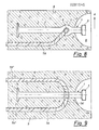
- FIG. 8 shows a section corresponding to FIG. 7 with another reinforcement insert
- FIG. 9 shows a section corresponding to FIG. 6 with the reinforcement insert according to FIG. 8.
- 1 denotes the anchor as a whole, it consists of an anchor bolt 2, an anchor head 3 for attacking a known lifting device, not shown, and optionally a widened anchor base 4.
- the anchor bolt 2 is provided with a thickening 5, which is approximately cylindrical; the axis 5 ⁇ of this cylinder runs approximately perpendicular to the axis 2 ⁇ of the anchor bolt 2 (see FIG. 2).
- This cylindrical thickening 5 is provided with a preferably circular transverse hole 6 which runs in the direction of the axis 5 ⁇ .
- This transverse hole 6 serves to receive an additional reinforcement (concrete iron) 7, 7A as is shown in FIGS. 6 to 9, for example.
- the diameter of the cylinder forming the thickening 5 is expediently approximately twice the diameter of the anchor bolt 2 and the height of this cylinder corresponds approximately to the diameter of the anchor bolt 2.
- FIGS. 6 to 9 show installation examples of the anchor 1 according to the invention in a plate-shaped precast concrete part 9; the upper part of the anchor bolt 2 protrudes with the anchor head 3 into a hemispherical recess 8 on an end face of the precast concrete part 9, which is provided in a known manner for engaging the connecting head of the lifting device on the anchor head 3.
- the additional reinforcement (concrete iron) 7A inserted through the transverse hole 6 in the anchor 1 is also U-shaped or. Is bent in a V-shape, but the apex 7A ⁇ of this reinforcing bar 7A has a bend or angled so that a plane through the two legs 7A ⁇ of the reinforcing bar 7A is at a distance from the anchor bolt 2 and parallel to it.
- the precast concrete part 9 is expediently set in the direction of arrow A in FIG. 8.
Landscapes
- Engineering & Computer Science (AREA)
- Architecture (AREA)
- Mechanical Engineering (AREA)
- Civil Engineering (AREA)
- Structural Engineering (AREA)
- Joining Of Building Structures In Genera (AREA)
Abstract
Description
- Die Erfindung betrifft einen Anker zum Transportieren und Manipulieren von Schwerlasten, insbesondere Betonfertigteilen, mittels eines Hebezeuges, bestehend aus einem Ankerbolzen und einem Ankerkopf sowie gegebenenfalls einem verbreiterten Ankerfuß.
- Solche Anker werden vielfach verwendet und zwar im Zusammenhang mit Manipulier- und Hebevorrichtungen, wie sie beispielsweise aus den AT-PSen 283 691 und 358 788 bekannt sind.
- Ziel der Erfindung ist es, einen solchen Anker dahingehend zu verbessern, daß eine bessere Einleitung der Kräfte in die Schwerlast, insbesondere die Betonfertigteile, erfolgt und daß vor allem eine bessere Aufnahme der Spaltzugkräfte beim Aufstellen und eine Vermeidung von Abplatzungen erreicht wird. Dies ist insbesondere bei dünnen Betonfertigteilen, bei niedriger Betonfestigkeit, bei Leichtbeton sowie bei Leca-, Schlacken- und Schlammbeton od.dgl. wesentlich.
- Dies wird bei dem eingangs näher bezeichneten Anker erfindungsgemäß dadurch erreicht, daß der Ankerbolzen in seinem an den Ankerkopf anschließenden Drittel seiner Längserstreckung mit einer an sich bekannten Verdickung von der ungefähren Form eines Zylinders versehen ist, wobei die Achse dieses Zylinders etwa senkrecht zur Ankerbolzen-Achse angeordnet und dieser Zylinder in Richtung seiner Achse mit einem vorzugsweise kreisrunden Querloch versehen ist.
- Aus der DE-OS 22 35 553 ist eine Verankerungsvorrichtung für Betonbauteile bekannt, die ein Verbindungselement zur Herstellung der Verbindung mit einer Transporteinrichtung, z.B. einem Hebezeug, und ein Verankerungsorgan zur Verankerung im Betonbauteil besitzt, bei welcher am oberen Ende eines schaftartigen Verbindungsgliedes bzw. Bolzens eine Querbohrung mit durchgestecktem Querstab vorgesehen ist, jedoch dient dieser Querstab zum Unterschied von der vorliegenden Erfindung als Verbindungselement zur Herstellung der Verbindung mit dem Transportzeug somit als Anker kopf; gemäß einer anderen aus dieser Druckschrift bekannten Ausführungsform ist am unteren Ende des Bolzens ein angeschmiedeter Querstab vorgesehen, der als Ankerfuß dient.
- Aus der DE-AS 22 23 519 ist eine Vorrichtung zum Anhängen eines Betonfertigteils an ein Hebezeug bekannt, bei welcher zum Unterschied von der vorliegenden Erfindung der Ankerbolzen an seinem unteren Ende eine Verdickung mit einem zylindrischen Querloch zum Durchstecken eines Bewehrungsstabes, der somit den Ankerfuß darstellt, aufweist.
- Gegenstand der Erfindung ist weiters eine in einem Betonfertigteil einbetonierte Hebevorrichtung unter Verwendung eines erfindungsgemäßen Ankers, die dadurch gekennzeichnet ist, daß durch das Querloch des Ankerbolzens in an sich bekannter Weise ein Bewehrungseisen in der Form eines U bzw. V geführt ist und daß der Scheitel dieses Bewehrungseisens mit einer Abkröpfung bzw. Abwinkelung versehen ist, so daß eine durch die beiden Schenkel des U- bzw. V-förmigen Bewehrungseisens gelegte Ebene im Abstand zum Ankerbolzen und parallel zu diesem verläuft.
- Dadurch wird eine bessere räumliche Verteilung des Kraftangriffs durch den Anker im Beton erreicht.
- Die Erfindung wird nun an Hand von Ausführungsbeispielen unter Bezugnahme auf die Zeichnungen näher erläutert; in diesen zeigen Fig. 1 eine Ansicht des erfindungsgemäßen Ankers, Fig. 2 eine zu Fig. 1 um 90° verdrehte Ansicht des Ankers, teilweise im Schnitt, Fig. 3 eine Schnittansicht längs der Linie III-III in Fig. 2, Fig. 4 eine Draufsicht auf den Anker in der Stellung gemäß Fig. 2, Fig. 5 eine Schnittansicht längs der Linie V-V in Fig. 1, Fig. 6 einen Schnitt durch einen plattenförmigen Betonfertigteil in der Ebene dessen größter Abmessungen an der Stelle des Ankers, Fig. 7 einen analogen Schnitt längs einer gegenüber Fig. 6 um 90° verdrehten Ebene, Fig. 8 einen Schnitt entsprechend Fig. 7 mit einer anderen Bewehrungseinlage und Fig. 9 einen Schnitt entsprechend der Fig. 6 mit der Bewehrungseinlage gemäß Fig. 8.
- In den Fig. 1 bis 9 ist mit 1 der Anker als Ganzes bezeichnet, er besteht aus einem Ankerbolzen 2, einem Ankerkopf 3 zum Angriff einer nicht dargestellten, bekannten Hebevorrichtung und gegebenenfalls einem verbreiterten Ankerfuß 4. Im oberen, d.h. an den Ankerkopf 3 anschließenden Drittel seiner Längserstreckung ist der Ankerbolzen 2 mit einer Verdickung 5 versehen, die ungefähr zylinderförmig ist; die Achse 5ʹ dieses Zylinders verläuft etwa senkrecht zur Achse 2ʹ des Ankerbolzens 2 (vgl. Fig. 2). Diese zylinderförmige Verdickung 5 ist mit einem vorzugsweise kreisförmigen Querloch 6 versehen, das in Richtung der Achse 5ʹ verläuft.
- Dieses Querloch 6 dient zur Aufnahme einer Zusatzbewehrung (Betoneisen) 7, 7A wie dies in den Fig. 6 bis 9 beispielsweise dargestellt ist.
- Zweckmäßigerweise ist der Durchmesser des die Verdickung 5 bildenden Zylinders etwa doppelt so groß wie der Durchmesser des Ankerbolzens 2 und die Höhe dieses Zylinders entspricht etwa dem Durchmesser des Ankerbolzens 2.
- In den Fig. 6 bis 9 sind Einbaubeispiele des erfindungsgemäßen Ankers 1 in einem plattenförmigen Betonfertigteil 9 dargestellt; dabei ragt der obere Teil des Ankerbolzens 2 mit dem Ankerkopf 3 in eine halbkugelförmige Aussparung 8 an einer Stirnseite des Betonfertigteils 9, die zum Angriff des Verbindungskopfes der Hebevorrichtung am Ankerkopf 3 in bekannter Weise vorgesehen ist.
- Dabei ist in der Fig. 6 oder 7 der normale Einbaufall des Ankers 1 mit U- bzw. V-förmiger Zusatzbewehrung (Betoneisen) 7, der eine bessere Verteilung der in den Betonteil 9 vom Anker 1 einzuleitenden Kräfte bewirkt bzw. ein Herausziehen des Ankers 1 verhindert, dargestellt. Die Bewehrung 7 ist dabei durch das Querloch 6 im Anker 1 geführt. Mit dem Pfeil 7 ist die auf den Ankerkopf 3 einwirkende Zugkraft angedeutet.
- In den Fig. 8 und 9 ist ein spezieller Fall einer Spaltzugbewehrung dargestellt, bei welchem die durch das Querloch 6 im Anker 1 gesteckte Zusatzbewehrung (Betoneisen) 7A ebenfalls U-bzw. V-förmig gebogen ist, wobei aber der Scheitel 7Aʹ dieses Bewehrungseisens 7A eine Abkröpfung bzw. Abwinkelung aufweist, so daß eine durch die beiden Schenkel 7Aʺ des Bewehrungseisens 7A gelegte Ebene im Abstand zum Ankerbolzen 2 und parallel zu diesem verläuft. Das Aufstellen des Betonfertigteils 9 erfolgt zweckmäßig in Richtung des Pfeils A in Fig. 8 .
Claims (2)
Applications Claiming Priority (2)
| Application Number | Priority Date | Filing Date | Title |
|---|---|---|---|
| AT48487A AT396279B (de) | 1987-03-04 | 1987-03-04 | Anker zum transportieren und manipulieren von schwerlasten |
| AT484/87 | 1987-03-04 |
Publications (3)
| Publication Number | Publication Date |
|---|---|
| EP0281545A2 true EP0281545A2 (de) | 1988-09-07 |
| EP0281545A3 EP0281545A3 (en) | 1989-04-26 |
| EP0281545B1 EP0281545B1 (de) | 1991-07-03 |
Family
ID=3491823
Family Applications (1)
| Application Number | Title | Priority Date | Filing Date |
|---|---|---|---|
| EP19880890010 Expired - Lifetime EP0281545B1 (de) | 1987-03-04 | 1988-01-20 | Anker zum Transportieren und Manipulieren von Schwerlasten |
Country Status (3)
| Country | Link |
|---|---|
| EP (1) | EP0281545B1 (de) |
| AT (1) | AT396279B (de) |
| DE (1) | DE3863445D1 (de) |
Cited By (2)
| Publication number | Priority date | Publication date | Assignee | Title |
|---|---|---|---|---|
| DE4341329A1 (de) * | 1993-12-03 | 1995-06-08 | Leonhard Nasl | Eingußdübel |
| US20130119686A1 (en) * | 2009-07-17 | 2013-05-16 | Casne Verige Pty Ltd | Concrete lifting anchors |
Citations (5)
| Publication number | Priority date | Publication date | Assignee | Title |
|---|---|---|---|---|
| FR2054723A5 (de) * | 1969-07-24 | 1971-05-07 | Loire Atel Forges | |
| DE2603805A1 (de) * | 1976-02-02 | 1977-08-04 | Modersohn Gmbh & Co Kg Wilh | Ankerschiene, anschweissplatte oder dergleichen mit einem angeschweissten verankerungsstueck |
| FR2379672A1 (fr) * | 1977-02-03 | 1978-09-01 | Fricker Frimeda Metall Draht | Piece d'ancrage destinee au soulevement et au transport d'elements prefabriques de beton |
| DE3005975A1 (de) * | 1980-02-18 | 1981-09-03 | Walther Ing.(grad.) 4952 Porta Westfalica Schröder | Vorrichtung zur lastaufnahme von betonfertigteilen |
| US4627198A (en) * | 1984-09-17 | 1986-12-09 | The Burke Company | Hoisting anchor assembly for use in cast concrete panels and method |
Family Cites Families (2)
| Publication number | Priority date | Publication date | Assignee | Title |
|---|---|---|---|---|
| DE2223519C3 (de) * | 1972-05-13 | 1975-07-03 | Haeussler, Ernst, Dr.-Ing., 4300 Essen | Vorrichtung zum Anhängen eines Betonfertigteile an ein Hebezeug |
| DE2235553A1 (de) * | 1972-07-20 | 1974-01-31 | Reinhold Michel | Verankerungsvorrichtung fuer betonbauteile |
-
1987
- 1987-03-04 AT AT48487A patent/AT396279B/de not_active IP Right Cessation
-
1988
- 1988-01-20 DE DE8888890010T patent/DE3863445D1/de not_active Expired - Fee Related
- 1988-01-20 EP EP19880890010 patent/EP0281545B1/de not_active Expired - Lifetime
Patent Citations (5)
| Publication number | Priority date | Publication date | Assignee | Title |
|---|---|---|---|---|
| FR2054723A5 (de) * | 1969-07-24 | 1971-05-07 | Loire Atel Forges | |
| DE2603805A1 (de) * | 1976-02-02 | 1977-08-04 | Modersohn Gmbh & Co Kg Wilh | Ankerschiene, anschweissplatte oder dergleichen mit einem angeschweissten verankerungsstueck |
| FR2379672A1 (fr) * | 1977-02-03 | 1978-09-01 | Fricker Frimeda Metall Draht | Piece d'ancrage destinee au soulevement et au transport d'elements prefabriques de beton |
| DE3005975A1 (de) * | 1980-02-18 | 1981-09-03 | Walther Ing.(grad.) 4952 Porta Westfalica Schröder | Vorrichtung zur lastaufnahme von betonfertigteilen |
| US4627198A (en) * | 1984-09-17 | 1986-12-09 | The Burke Company | Hoisting anchor assembly for use in cast concrete panels and method |
Cited By (3)
| Publication number | Priority date | Publication date | Assignee | Title |
|---|---|---|---|---|
| DE4341329A1 (de) * | 1993-12-03 | 1995-06-08 | Leonhard Nasl | Eingußdübel |
| US20130119686A1 (en) * | 2009-07-17 | 2013-05-16 | Casne Verige Pty Ltd | Concrete lifting anchors |
| US8746770B2 (en) * | 2009-07-17 | 2014-06-10 | Robert Sladojevic | Concrete lifting anchors |
Also Published As
| Publication number | Publication date |
|---|---|
| DE3863445D1 (de) | 1991-08-08 |
| AT396279B (de) | 1993-07-26 |
| ATA48487A (de) | 1992-11-15 |
| EP0281545B1 (de) | 1991-07-03 |
| EP0281545A3 (en) | 1989-04-26 |
Similar Documents
| Publication | Publication Date | Title |
|---|---|---|
| EP0211256B1 (de) | Anker zum Einbetonieren in schwere Lasten | |
| EP0163008B1 (de) | Hebe- und Transportvorrichtung | |
| EP3081708A1 (de) | Ankerschiene zur verankerung im beton | |
| EP0500029B1 (de) | Flachstahlbetonanker für Betonfertigteile | |
| CH698304B1 (de) | Drahtseilanker, insbesondere für Steinschlag- oder Lawinenschutzverbauungen. | |
| EP3037606B1 (de) | Lastaufnahmemittel | |
| DE3312458A1 (de) | Transportanker fuer betonfertigteile | |
| DE2704435A1 (de) | Aufstell- und transportanker fuer betonfertigteile | |
| DE3212634A1 (de) | Haltevorrichtung fuer pfosten von gelaendern | |
| DE102009041654A1 (de) | Eingiessbare Ankerschiene | |
| EP0281545B1 (de) | Anker zum Transportieren und Manipulieren von Schwerlasten | |
| WO1987005817A1 (fr) | Mousqueton, en particulier pour alpinistes | |
| DE3020801A1 (de) | Tellerfuss-transportanker | |
| DE2223519A1 (de) | Vorrichtung zum anhaengen eines betonfertigteils an ein hebezeug | |
| DE10116673A1 (de) | Transportanker | |
| DE2039263A1 (de) | Ankerhuelse fuer Betonfertigteile | |
| EP1561877A2 (de) | Verbindungsvorrichtung | |
| DE3123175C1 (de) | Anschlußvorrichtung | |
| AT394599B (de) | Waermedaemmender bauteil | |
| DE2518398A1 (de) | Einrichtung zum heben und transportieren von betonfertigteilen o.dgl. | |
| DE1808988A1 (de) | Vorrichtung und Verfahren zum Manipulieren derselben fuer den Transport von Stahlbetonraumkoerpern,insbesondere von Stahlbetonfertiggaragen | |
| DE2721709A1 (de) | Ziehgeraet zum ausbeulen von karosserieteilen | |
| DE2208294A1 (de) | Befestigungsteil | |
| DE102004048365A1 (de) | Mast | |
| DE3116619C2 (de) | Verpreßanker, insbesondere Daueranker |
Legal Events
| Date | Code | Title | Description |
|---|---|---|---|
| PUAI | Public reference made under article 153(3) epc to a published international application that has entered the european phase |
Free format text: ORIGINAL CODE: 0009012 |
|
| AK | Designated contracting states |
Kind code of ref document: A2 Designated state(s): BE CH DE FR GB IT LI LU NL SE |
|
| PUAL | Search report despatched |
Free format text: ORIGINAL CODE: 0009013 |
|
| AK | Designated contracting states |
Kind code of ref document: A3 Designated state(s): BE CH DE FR GB IT LI LU NL SE |
|
| 17P | Request for examination filed |
Effective date: 19890324 |
|
| 17Q | First examination report despatched |
Effective date: 19900305 |
|
| GRAA | (expected) grant |
Free format text: ORIGINAL CODE: 0009210 |
|
| AK | Designated contracting states |
Kind code of ref document: B1 Designated state(s): BE CH DE FR GB IT LI LU NL SE |
|
| GBT | Gb: translation of ep patent filed (gb section 77(6)(a)/1977) | ||
| REF | Corresponds to: |
Ref document number: 3863445 Country of ref document: DE Date of ref document: 19910808 |
|
| ET | Fr: translation filed | ||
| ITF | It: translation for a ep patent filed |
Owner name: BUGNION S.P.A. |
|
| PLBE | No opposition filed within time limit |
Free format text: ORIGINAL CODE: 0009261 |
|
| STAA | Information on the status of an ep patent application or granted ep patent |
Free format text: STATUS: NO OPPOSITION FILED WITHIN TIME LIMIT |
|
| 26N | No opposition filed | ||
| EPTA | Lu: last paid annual fee | ||
| EAL | Se: european patent in force in sweden |
Ref document number: 88890010.7 |
|
| PGFP | Annual fee paid to national office [announced via postgrant information from national office to epo] |
Ref country code: LU Payment date: 19960101 Year of fee payment: 9 |
|
| PGFP | Annual fee paid to national office [announced via postgrant information from national office to epo] |
Ref country code: GB Payment date: 19960109 Year of fee payment: 9 |
|
| PGFP | Annual fee paid to national office [announced via postgrant information from national office to epo] |
Ref country code: CH Payment date: 19960118 Year of fee payment: 9 |
|
| PGFP | Annual fee paid to national office [announced via postgrant information from national office to epo] |
Ref country code: SE Payment date: 19960124 Year of fee payment: 9 |
|
| PGFP | Annual fee paid to national office [announced via postgrant information from national office to epo] |
Ref country code: FR Payment date: 19960129 Year of fee payment: 9 |
|
| PGFP | Annual fee paid to national office [announced via postgrant information from national office to epo] |
Ref country code: NL Payment date: 19960131 Year of fee payment: 9 |
|
| PGFP | Annual fee paid to national office [announced via postgrant information from national office to epo] |
Ref country code: BE Payment date: 19960207 Year of fee payment: 9 |
|
| PG25 | Lapsed in a contracting state [announced via postgrant information from national office to epo] |
Ref country code: LU Free format text: LAPSE BECAUSE OF NON-PAYMENT OF DUE FEES Effective date: 19970120 Ref country code: GB Effective date: 19970120 |
|
| PG25 | Lapsed in a contracting state [announced via postgrant information from national office to epo] |
Ref country code: SE Effective date: 19970121 |
|
| PG25 | Lapsed in a contracting state [announced via postgrant information from national office to epo] |
Ref country code: LI Effective date: 19970131 Ref country code: CH Effective date: 19970131 Ref country code: BE Effective date: 19970131 |
|
| BERE | Be: lapsed |
Owner name: RISS G.M.B.H. Effective date: 19970131 |
|
| PG25 | Lapsed in a contracting state [announced via postgrant information from national office to epo] |
Ref country code: NL Effective date: 19970801 |
|
| GBPC | Gb: european patent ceased through non-payment of renewal fee |
Effective date: 19970120 |
|
| REG | Reference to a national code |
Ref country code: CH Ref legal event code: PL |
|
| PG25 | Lapsed in a contracting state [announced via postgrant information from national office to epo] |
Ref country code: FR Effective date: 19970930 |
|
| NLV4 | Nl: lapsed or anulled due to non-payment of the annual fee |
Effective date: 19970801 |
|
| EUG | Se: european patent has lapsed |
Ref document number: 88890010.7 |
|
| REG | Reference to a national code |
Ref country code: FR Ref legal event code: ST |
|
| PGFP | Annual fee paid to national office [announced via postgrant information from national office to epo] |
Ref country code: DE Payment date: 19980112 Year of fee payment: 11 |
|
| PG25 | Lapsed in a contracting state [announced via postgrant information from national office to epo] |
Ref country code: DE Free format text: LAPSE BECAUSE OF NON-PAYMENT OF DUE FEES Effective date: 19991103 |
|
| PG25 | Lapsed in a contracting state [announced via postgrant information from national office to epo] |
Ref country code: IT Free format text: LAPSE BECAUSE OF NON-PAYMENT OF DUE FEES;WARNING: LAPSES OF ITALIAN PATENTS WITH EFFECTIVE DATE BEFORE 2007 MAY HAVE OCCURRED AT ANY TIME BEFORE 2007. THE CORRECT EFFECTIVE DATE MAY BE DIFFERENT FROM THE ONE RECORDED. Effective date: 20050120 |