EP0281075A2 - Material für Übertragung durch Wärme - Google Patents
Material für Übertragung durch Wärme Download PDFInfo
- Publication number
- EP0281075A2 EP0281075A2 EP19880103079 EP88103079A EP0281075A2 EP 0281075 A2 EP0281075 A2 EP 0281075A2 EP 19880103079 EP19880103079 EP 19880103079 EP 88103079 A EP88103079 A EP 88103079A EP 0281075 A2 EP0281075 A2 EP 0281075A2
- Authority
- EP
- European Patent Office
- Prior art keywords
- transfer material
- thermal transfer
- ink
- ink layer
- material according
- Prior art date
- Legal status (The legal status is an assumption and is not a legal conclusion. Google has not performed a legal analysis and makes no representation as to the accuracy of the status listed.)
- Granted
Links
Images


Classifications
-
- B—PERFORMING OPERATIONS; TRANSPORTING
- B41—PRINTING; LINING MACHINES; TYPEWRITERS; STAMPS
- B41M—PRINTING, DUPLICATING, MARKING, OR COPYING PROCESSES; COLOUR PRINTING
- B41M5/00—Duplicating or marking methods; Sheet materials for use therein
- B41M5/26—Thermography ; Marking by high energetic means, e.g. laser otherwise than by burning, and characterised by the material used
- B41M5/382—Contact thermal transfer or sublimation processes
- B41M5/38228—Contact thermal transfer or sublimation processes characterised by the use of two or more ink layers
-
- Y—GENERAL TAGGING OF NEW TECHNOLOGICAL DEVELOPMENTS; GENERAL TAGGING OF CROSS-SECTIONAL TECHNOLOGIES SPANNING OVER SEVERAL SECTIONS OF THE IPC; TECHNICAL SUBJECTS COVERED BY FORMER USPC CROSS-REFERENCE ART COLLECTIONS [XRACs] AND DIGESTS
- Y10—TECHNICAL SUBJECTS COVERED BY FORMER USPC
- Y10S—TECHNICAL SUBJECTS COVERED BY FORMER USPC CROSS-REFERENCE ART COLLECTIONS [XRACs] AND DIGESTS
- Y10S428/00—Stock material or miscellaneous articles
- Y10S428/913—Material designed to be responsive to temperature, light, moisture
-
- Y—GENERAL TAGGING OF NEW TECHNOLOGICAL DEVELOPMENTS; GENERAL TAGGING OF CROSS-SECTIONAL TECHNOLOGIES SPANNING OVER SEVERAL SECTIONS OF THE IPC; TECHNICAL SUBJECTS COVERED BY FORMER USPC CROSS-REFERENCE ART COLLECTIONS [XRACs] AND DIGESTS
- Y10—TECHNICAL SUBJECTS COVERED BY FORMER USPC
- Y10S—TECHNICAL SUBJECTS COVERED BY FORMER USPC CROSS-REFERENCE ART COLLECTIONS [XRACs] AND DIGESTS
- Y10S428/00—Stock material or miscellaneous articles
- Y10S428/914—Transfer or decalcomania
-
- Y—GENERAL TAGGING OF NEW TECHNOLOGICAL DEVELOPMENTS; GENERAL TAGGING OF CROSS-SECTIONAL TECHNOLOGIES SPANNING OVER SEVERAL SECTIONS OF THE IPC; TECHNICAL SUBJECTS COVERED BY FORMER USPC CROSS-REFERENCE ART COLLECTIONS [XRACs] AND DIGESTS
- Y10—TECHNICAL SUBJECTS COVERED BY FORMER USPC
- Y10T—TECHNICAL SUBJECTS COVERED BY FORMER US CLASSIFICATION
- Y10T428/00—Stock material or miscellaneous articles
- Y10T428/24—Structurally defined web or sheet [e.g., overall dimension, etc.]
- Y10T428/24802—Discontinuous or differential coating, impregnation or bond [e.g., artwork, printing, retouched photograph, etc.]
- Y10T428/24893—Discontinuous or differential coating, impregnation or bond [e.g., artwork, printing, retouched photograph, etc.] including particulate material
- Y10T428/24901—Discontinuous or differential coating, impregnation or bond [e.g., artwork, printing, retouched photograph, etc.] including particulate material including coloring matter
-
- Y—GENERAL TAGGING OF NEW TECHNOLOGICAL DEVELOPMENTS; GENERAL TAGGING OF CROSS-SECTIONAL TECHNOLOGIES SPANNING OVER SEVERAL SECTIONS OF THE IPC; TECHNICAL SUBJECTS COVERED BY FORMER USPC CROSS-REFERENCE ART COLLECTIONS [XRACs] AND DIGESTS
- Y10—TECHNICAL SUBJECTS COVERED BY FORMER USPC
- Y10T—TECHNICAL SUBJECTS COVERED BY FORMER US CLASSIFICATION
- Y10T428/00—Stock material or miscellaneous articles
- Y10T428/31504—Composite [nonstructural laminate]
- Y10T428/31551—Of polyamidoester [polyurethane, polyisocyanate, polycarbamate, etc.]
-
- Y—GENERAL TAGGING OF NEW TECHNOLOGICAL DEVELOPMENTS; GENERAL TAGGING OF CROSS-SECTIONAL TECHNOLOGIES SPANNING OVER SEVERAL SECTIONS OF THE IPC; TECHNICAL SUBJECTS COVERED BY FORMER USPC CROSS-REFERENCE ART COLLECTIONS [XRACs] AND DIGESTS
- Y10—TECHNICAL SUBJECTS COVERED BY FORMER USPC
- Y10T—TECHNICAL SUBJECTS COVERED BY FORMER US CLASSIFICATION
- Y10T428/00—Stock material or miscellaneous articles
- Y10T428/31504—Composite [nonstructural laminate]
- Y10T428/31786—Of polyester [e.g., alkyd, etc.]
Definitions
- the present invention relates to a thermal transfer material for use in a recording method of transferring two-color images onto a recording medium such as plain paper.
- the thermal or heat-sensitive transfer recording method has recently been widely used because it has general advantages of the thermal recording method such that the apparatus employed is light in weight, compact, free of noise, excellent in operability and adapted to easy maintenance, and also has other advantages such that it does not require a color-formation type converted paper but provides recorded images with excellent durability.
- Japanese Laid-Open Patent Application No. 148591/1981 discloses a two-color type thermal transfer recording element (transfer material) comprising a substrate and two heat-fusible ink layers including a high-melting point ink layer A and a low-melting point ink layer B containing mutually different colorants disposed in this order on the substrate.
- a low thermal input energy is applied to the element, only the low-melting point layer B is transferred onto plain paper.
- a high thermal input energy is applied to the element, both the heat-fusible ink layers A and B are transferred onto the plain paper.
- two-color images can be obtained.
- Japanese Laid-Open Patent Application No. 64389/1984 discloses a two-color thermal transfer ink sheet which comprises, on a substrate, an ink layer comprising an ink which melt-exudes at a lower temperature and another ink which is melt-peeled at a higher temperature than the melt-exudation temperature.
- two-color recording is effected by changing the energy applied to a thermal head at two levels so as to change the temperature of the ink layers.
- a high energy is supplied to the ink layers to provide a high temperature
- a lower temperature portion is formed at the periphery of a higher temperature portion due to heat diffusion, so that a bordering of a lower temperature color is formed around the higher temperature printed image.
- a high energy is supplied to a thermal head, it requires a relatively long time until the thermal head is cooled so that a higher-temperature printed image is liable to be accompanied with a trailing of a lower-temperature color.
- Japanese Laid-Open Patent Application No. 295075/1986 discloses a thermal transfer material wherein at least one of a first ink layer and a second ink layer contains a silicone oil or a fluorine-containing surfactant so as to promote separation between the first and second ink layers.
- Japanese Laid-Open Patent Application No. 295079/1986 discloses a thermal transfer material wherein a fine powder layer not meltable under application of a heat energy for recording is disposed between a first ink layer and a second ink layer so as to easily cause separation therebetween.
- the quality of a recorded image is also improved by promoting sharp edge-cutting of a transferred image. It is, however, not always easy to effect such sharp edge-cutting in a transfer operation because it is influenced by various actual recording conditions such as a heat-application condition and a peeling condition among others.
- our research group has further proposed a thermal transfer material wherein the first ink layer comprises a binder having a glass transition temperature (Tg) of 0°C or below and 25 to 85 wt. % of a pigment (U.S. Patent Application Serial No. 106,819).
- Tg glass transition temperature
- thermal head of high definition having a large number of heating element dots has also been developed.
- thermal head of high definition It is preferred to use a thermal transfer material adapted to a high definition recording. If a conventional thermal transfer material is subjected to a recording using the above-mentioned thermal head of high definition an irregular transfer occurs at the periphery of a heat-applied portion and the edge portion of a printed image becomes uneven or irregular in some cases. Therefore, there has strongly been desired a thermal transfer material capable of providing a clear image even in combination with a thermal head of high definition.
- a principal object of the present invention is to provide a thermal transfer material by which two-color recorded images with respectively clear color tones are given on plain paper through a simple process, by solving the above-mentioned problems involved in the conventional two-color recording method.
- Another object of the present invention is to provide a thermal transfer material capable of providing a clear image even in combination with a heat-application means of high definition.
- a thermal transfer material comprising: a support and at least an adhesive layer, a first ink layer and a second ink layer disposed in this order on the support, wherein the adhesion strength F1 between the support and the first ink layer and the adhesion strength F2 between the first and second ink layers satisfy the relations of F1 > F2 at a higher temperature and F1 ⁇ F2 at a lower temperature; the adhesion strength F1 being in the range of 1.0 g/cm - 10 g/cm when the relation of F1 ⁇ F2 is satisfied after heating.
- a thermal transfer material 5 according to the present invention comprises a support 1, and a first adhesive layer 2, a first ink layer 3 and a second ink layer 4 disposed in this order on the support.
- the adhesion (strength) F2 between the first ink layer 3 and the second ink layer 4 and the adhesion (strength) F1 between the first ink layer 3 and the support 1 satisfy the relations of F1 > F2 at a higher temperature and F1 ⁇ F2 at a lower temperature.
- the transfer material of the present invention is supplied with heat, the separation between the first ink layer 3 and the second ink layer 4 is more readily caused than that between the first ink layer 3 and the support 1 immediately after the heating.
- the separation between the first ink layer 3 and the support 1 becomes relatively easier after a considerable time has passed from the heating until the separation of the support 1 from a recording medium, i.e., at the time when the transfer material 5 is cooled after the transfer material and the recording medium has been superposed, heated and retained for a substantial time after heating and before peeling.
- the relative adhesion between the second and first ink layers and that between the first ink layer and the support are evaluated according to such a standard that the latter adhesion is larger if the second ink layer is substantially selectively transferred, and that the former is larger if substantially both the ink layers are transferred, respectively, when transfer recording is effected on a recording medium.
- Such evaluation of the adhesions is not affected by the form of separation between ink layers (e.g., whether or not the separation between the second and first ink layers has occurred strictly at the boundary between these layers, etc.).
- the first adhesive layer 2 is disposed between the first ink layer 3 and the support 1 in order to control the adhesion F1 between these layers.
- the first adhesive layer 2 may preferably be one causing an irreversible decrease in the adhesion F1 through heating.
- the adhesion F2 between the first ink layer 3 and the second ink layer 4 decreases more sharply than the adhesion F1 between the first ink layer 3 and the support 1 on temperature increase due to heating by a thermal head.
- the adhesion F2 between the first ink layer 3 and the second ink layer 4 is weaker than the adhesion F1 between the first ink layer 3 and the support 1, at a time immediately after heating (i.e., before the temperature being lowered).
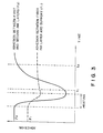
- the transfer material is peeled from a recording medium such as paper immediately after the transfer material is heated while the second ink layer 4 thereof being in contact with the recording medium, i.e., at a time t1 in Figure 3, only the second ink layer 4 is transferred to the recording medium.
- the adhesion F2 is recovered to be essentially the same as that before heating.
- the adhesion F1 between the first ink layer 3 and the support 1 is irreversibly decreased through heating because of the adhesive layer 2 in this embodiment, the adhesion F1 is not recovered to the state before heating.
- the adhesion F1 between the first ink layer 3 and the support 1 is weaker than the adhesion F2 between the first and second ink layers. Therefore, if the transfer material is peeled from the recording medium at this time, i.e., at a time t2 in Figure 3, the first ink layer 3 is transferred together with the second ink layer 4 to the recording medium.
- the first ink layer 3 and the second ink layer 4 are composed to have different color tones from each other in the thermal transfer material, two-color recording can be effected.
- the color of the first ink layer 3 and the second ink layer 4 are desired to be obtained substantially as they are, it is preferred to dispose a first ink layer 3 of a dark color such as black and a second ink layer 4 of a brighter color than that of the first ink layer such as red.
- the first and second ink layers can be made in the same hue but different in density from each other, whereby two-color images with dense and pale portions can be obtained in the same manner as described above.
- the first ink layer can function as a correcting ink layer by incorporating, e.g., a white pigment having a strong hiding power therein.
- the adhesion (F2) between the first ink layer 3 and the second ink layer 4 may recover its initial state with the elapse of time after heating.
- the adhesion F1 between the first ink layer 3 and the support 1 is clearly weaker than the adhesion F2 between the first and second ink layers at the time t2 in Figure 3.
- the adhesion F1 is 1.0 g/cm - 10 g/cm, more preferably 3 g/cm - 8 g/cm when a prescribed time has passed from the heat application, i.e., at a time at which both the first and second ink layers are transferred to a recording medium.
- the adhesion F1 is smaller than 1.0 g/cm, edge-cutting of the transferred image deteriorates whereby a clear image cannot be obtained.
- the adhesion F1 is larger than 10 g/cm, the transferability of the first ink layer deteriorates.
- adhesion F1 after heating may be measured in the following manner.
- An adhesive layer 2, a first ink layer 3 and a second ink layer 4 are successively formed on a support 1 of a polyethylene terephthalate (PET) film, respectively in coating amounts of 0.5 g/m2, 2.0 g/m2 and 2.0 g/m2, thereby to prepare a thermal transfer material 5.
- the thermal transfer material 5 is superposed on a recording medium (thermal transfer paper TC-80, mfd. by Honshu Seishi K.K.) so that the second ink layer 4 of the transfer material 5 contacts the recording medium, and heat is applied in a solid print pattern to the transfer material 5 from its support 1 side by means of a thermal head at an energy of 13 mJ/dot under a pressing force of 600 g/cm.
- the transfer material 5 and the recording medium are, as they are without peeling, loaded on a tensile strength tester (Tensilon RTM-100, Toyo Boldwin K.K.).
- a tensile strength tester Tetrachloro Tween 20
- the PET film 1 and the recording medium are peeled from each other at a peeling angle of 180 degrees at a peeling speed of 300 mm/min, at room temperature (25°C) so that the first ink layer is substantially transferred to the recording medium.
- a force required for such peeling is measured and converted to the strength thereof per a bonded width of 1 cm.
- the heat is applied to the thermal transfer material so that the entire surface of the ink layer thereof is bonded to the recording medium. Further, the above-mentioned peeling is effected from the end of the ink layer bonded to the recording medium so that the maximum strength Fmax may be determined without consideration of the cutting of the ink layer.
- the adhesion between the first ink layer and the support before heating cannot be measured.
- this adhesion between the first ink layer and the support may be measured.
- an adhesive layer 2 is formed on a 4.5 ⁇ m-thick PET film in a coating amount of 5 g/m2, and then an adhesive tape (Mytack Laminate Label ML-211, mfd. by Nichiban K.K.) is caused to closely contact the coating surface.
- the resultant laminate is cut into a 8 mm-wide tape thereby to prepare a sample, which is then boaded on the above-mentioned tensile strength tester.
- the adhesive layer 2 is peeled from the support at a peeling angle of 135 degrees, at a peeling speed of 500 mm/min and at an environmental temperature of 25°C. A force required for such peeling is measured and converted to the strength thereof per a bonded width of 1 cm.
- the adhesion of the adhesive layer before heating may be measured.
- the above-mentioned 8 mm-wide sample is heated up to 100°C and thereafter the adhesion may be measured according to the second measurement method.
- the adhesion after heating may also be measured according to the second measurement method.
- the adhesion between the support 1 and the first ink layer 3 may be measured by using a sample in the form of a thermal transfer material as it is.
- the adhesion (F1) between the support 1 and the first ink layer 3 after heating, measured according to the first measurement method is 1.0 - 10 g/cm.
- the adhesion F1 in a sample comprising a combination of a support and an adhesive layer, which are the same as those of the thermal transfer material of the present invention is measured according to the second measurement method, the adhesion after heating is 5.0 - 30 g/cm.
- the adhesion F1 before heating, when measured according to the second measurement method is 80 g/cm or larger. Therefore, it is found that the adhesion F1 irreversibly decreases through heating.
- an adhesive layer 2 is disposed between a support 1 and a first ink layer 3, and the adhesion F1 after heating, as compared with that before heating, does not recover the initial strength but irreversibly decreases to 1.0 - 10 g/cm.
- a heat-applied portion and a non-heat-applied portion of the adhesive layer 2 show clearly different behaviors whereby there is provided a transferred image of high definition excellent in edge-cutting and transferability, even when a thermal head having a heating element density of 160 dots/inch or 240 dots/inch is used.
- an adhesive layer 2 may preferably comprise a wax component A and an adhesive component B.
- the wax component A may preferably be in the form of particulates. It is preferred that these components A and B are mixed so that the initial adhesion F1 before heating becomes above a certain value and a problem such as a decrease in storability and ink dropout is not caused. More specifically, the weight proportion of the wax component A to the adhesive component B may preferably be 0.5 ⁇ A/B ⁇ 20 as described hereinafter.
- the adhesive component B is present as a binder around the particulate wax component A, and that the adhesive layer 2 bonds the first ink layer 3 to the support 1 so as not to cause an ink dropout, etc.
- the particulate wax component in the adhesive layer 2 is softened when once supplied with heat, and thereafter is formed into a film as it is cooled. As a result, the adhesive layer 2 is controlled by the film-formed wax component to decrease its flexibility, whereby the releasability thereof becomes stronger than the adhesion of the adhesive component.
- the adhesion F1 is so controlled as to decrease to 1.0 - 10.0 g/cm.
- the mixing proportion of the wax component A to the adhesive component B in the adhesive layer may preferably be 0.5 ⁇ A/B ⁇ 20 as described above, more preferably 1 ⁇ A/B ⁇ 9, particularly preferably 1.5 ⁇ A/B ⁇ 6.
- the adhesion thereof may irreversibly change. More specifically, the adhesion between the support 1 and the first ink layer 3 decreases from an initial adhesion before heat-application to an adhesion after the heat-application, and does not completely recover to the initial state.
- the particulate wax component A may preferably comprise a wax having a softening temperature of 60 - 150°C. Further, the particulate wax component A may preferably have a particle size smaller than the thickness of the adhesive layer 2. More specifically, the particulate wax component A may preferably have an average particle size of about 0.05 - 5 ⁇ m.
- the wax component may be selected, as a single species or a combination of two or more species as desired, from the following known materials: natural waxes such as whale wax, beeswax, lanolin, carnauba wax, candelilla wax, montan wax and ceresin wax; petroleum waxes such as paraffin wax and micro-crystalline wax; synthetic waxes such as ester wax, low-molecular weight polyethylene, Fischer-Tropsch wax and the like; higher fatty acids such as lauric acid, myristic acid, palmitic acid, stearic acid, and behenic acid; higher alcohols such as stearyl alcohol and behenyl alcohol; esters such as fatty acid esters of sucrose and fatty acid esters of sorbitane; amides such as oleic amide; etc.
- natural waxes such as whale wax, beeswax, lanolin, carnauba wax, candelilla wax, montan wax and ceresin wax
- petroleum waxes such
- a wax having a softening temperature of below 60°C is used, the particulate characteristics thereof may be lost gradually in a storage state, or may cause an offset of the ink layer in storage at a high temperature (at about 60°C).
- a wax having a softening temperature of above 150°C is used, the quantity of heat applied in a recording may be insufficient and cannot cause a sufficiently melted state whereby it is difficult to cause an intended irreversible change.
- the wax component particularly preferably used in the present invention is a polyethylene wax having a softening temperature of 80°C - 150°C and a number-average molecular weight of 1,000 - 6,000, more preferably a polyethylene wax having a softening temperature of 90°C - 140°C and a number-average molecular weight of 2,000 - 5,000, further preferably an oxidized polyethylene wax having a softening temperature of 90°C - 140°C and a number-average molecular weight of 2,000 - 5,000.
- the "softening temperature” used in the present invention is a flow initiation temperature as obtained from an apparent viscosity-temperature curve of a sample based on a measurement by a flow tester (Model: CFT500, available from Shimazu Seisakusho K.K.) under the conditions of a load of 10 kg, and a temperature increasing rate of 2°C/min.
- the number-average molecular weight Mn of polyethylene wax is measured in the following manner.
- VPO Var Pressure Osmometry Method
- a sample of polyethylene wax is dissolved in a solvent such as benzene at varous concentrations (C) in the range of 0.2 to 1.0 g/100 ml to prepare several solutions.
- the adhesive component B may be selected, as a single species or a combination of two or more species as desired, from the following materials: polyamide resins, polyester resins, epoxy resins having an extremely high molecular weight, polyurethane resins, acrylic resins (e.g., polymethyl methacrylate, polyacrylamide, etc.), vinyl resins such as polyvinyl pyrrolidone, polyvinyl chloride resins (e.g., vinyl chloride-vinylidene chloride copolymers, vinyl chloride-vinyl acetate copolymers, etc.), cellulose resins (e.g., methyl cellulose, ethyl cellulose, carboxymethyl cellulose, etc.), polyvinyl alcohol resins (e.g., polyvinyl alcohol, partially saponified polyvinyl alcohol, etc.), petroleum resins, rosin derivatives, coumarone-indene resins, terpene resins, novolak-type phenolic resins, polystyren
- the adhesive component B may preferably have a softening temperature of 300°C or below, particularly 250°C or below.
- the adhesive component B may be in a softened state at room temperature. Further, the adhesive component B has a glass transition temperature (Tg) of 0°C or below.
- a polyurethane resin may preferably be used as the adhesive component B.
- a polyurethane resin preferably used in the present invention may be obtained by the following poly-addition reaction of a diisocyanate with a glycol:
- polyurethane resin there are two types, i.e., a polyether-type resin comprising a diisocyanate such as tolylenediisocyanate and methylenediphenyldiisocyanate, and a hydroxy compound such as polyoxypropylene glycol and polyoxypropylene-polyoxyethylene glycol; and a polyester-type resin mainly of a condensation product comprising adipic acid and ethylene glycol.
- polyether-polyurethane polyester-polyurethane
- polyester-polyurethane may preferably be used in the thermal transfer material according to the present invention.
- an adhesive component is mixed with a wax component preferably comprising a polyethylene wax (particularly an oxidized polyethylene) whereby the adhesion thereof has a characteristic such that it irreversibly decreases through heat-application.
- the adhesive layer 2 according to the present invention preferably has a softening temperature of 60 - 200°C.
- the first ink layer 3 comprises a resin, as a binder, and a colorant.
- the resin used in the first ink layer 3 has a glass transition temperature of 0°C or below, preferably -10°C or below, and preferably has a relatively large tensile elongation of 300 % or above, more preferably 500 % or above.
- a relatively large amount of a colorant particularly a pigment may preferably be added to the binder, whereby the tensile elongation and tensile strength thereof are suppressed.
- the tensile elongation used herein is the proportion of a change in length to an original length.
- the tensile elongation is based on values measured by using a sample in the form of a flat dumbbell having a thickness of 50 ⁇ m and a width (a narrow portion) of 6 mm, and using a tensile tester (Tensilon RTM-100, mfd. by Toyo Boldwin K.K.) at a pulling speed of 300 mm/sec at room temperature (25°C).
- the binder used in the first ink layer 3 has a glass transition temperature of 0°C or below, the binder is always in the state of a kind of supercooled liquid in the time of printing and storage. As a result, the first ink layer does not show brittleness. Accordingly, the first ink layer 3 is not transferred partially when only the second ink layer 4 is intended to be transferred.
- the binder preferably has a relatively large tensile elongation. If the binder has a tensile elongation of below 300 %, there are some cases wherein the first ink layer shows brittleness.
- the binder used in the first ink layer 3 which satisfies the above-mentioned conditions may include: acrylate copolymers such as alkyl acrylates copolymers, acrylonitrile-alkyl acrylate copolymers, styrene-alkyl acrylate copolymers, and alkyl methacrylate-alkyl acrylate copolymers; latexes such as styrene-butadiene latexes, nitrile-butadiene latexes, acrylic latexes, and vinyl acetate latexes; urethane resins such as polyester-type urethanes, polyether-type urethanes; etc. These binders may be used singly or as appropriate mixtures. Further, as desired, another binder material such as waxes or resins or another additive may be added to the above-mentioned binders.
- acrylate copolymers such as alkyl acrylates
- the relatively small tensile strength and tensile elongation of the first ink layer 3 may be realized by adding a relatively large amount of a pigment to the above binder.
- the pigment content in the first ink layer 3 is generally 25 - 85 %, preferably 35 - 70 % based on the weight of the first ink layer, while the pigment content may desirably be optimized by changing it depending on the property of the adhesive layer or the second ink layer.
- the pigment content is below 25 %, the decrease in the tensile strength and tensile elongation of the binder is insufficient.
- the pigment content is above 85 %, the first ink layer becomes brittle whereby the separation of colors is insufficient when only the second ink layer is intended to be transferred.
- a second adhesive layer 6 may be disposed, as desired, between the first ink layer 3 and second ink layer 4.
- materials constituting the first and second ink layers, or the pigment content of these ink layers may be selected from a wider scope thereof.
- the second adhesive layer 6 should preferably be so composed as to provide a softening temperature which is equal to or lower than that of the second ink layer 4.
- a recording is conducted by a thermal head
- the trailing end portion of the image portion in the moving direction of the thermal head changes from a printing temperature to a non-printing temperature.
- the first ink layer 3 can be transferred along with the second ink layer 4 to unintensionally provide the color of the first ink layer 3. This phenomenon can be prevented by setting the softening temperature of the second adhesive layer 6 to be equal to or lower than that of the second ink layer 4 as described above.
- the second adhesive layer 6 may preferably have a softening temperature of 60 - 130°C, more preferably 70 - 100°C. Further, it is preferred that the second adhesive layer 6 is so composed as to provide a melt viscosity (by a rotary viscometer) in the range of 1 cps to 100,000 cps at a temperature which is 30°C higher than the softening temperature thereof.
- the second ink layer 4 may preferably have a softening temperature of 60 - 200°C, more preferably 80 - 150°C. Further, a third adhesive layer may be disposed on the second ink layer 4 as desired, in order to improve the transfer characteristics of the ink layer to a recording medium.
- the ink layers and the adhesive layer on the support 1 may preferably have a thickness of not exceeding 20 ⁇ m in total. Further, it is preferred that each of the first ink layer 3, second ink layer 4, first adhesive layer 2 and second adhesive layer 6 has a thickness in the range of 0.1 - 10 ⁇ m.
- the support 1 of the thermal transfer material it is possible to use films of, e.g., polyester, aramide resin, nylon, polycarbonate, or paper such as capacitor paper, preferably having a thickness of about 2 to 12 ⁇ m. Too thick a support is not desirable because the heat conductivity becomes inferior. If a sufficient heat resistance and a strength are attained, a support can be thinner than 2 ⁇ m.
- the second ink layer 4 and the optional second adhesive layer 6 may comprise a binder as described below, singly or as an appropriate mixture, to which a colorant and another additive may be added as desired.
- binder may includes: waxes including: natural waxes such as whale wax, beeswax, lanolin, carnauba wax, candelilla wax, montan wax and ceresin wax; petroleum waxes such as paraffin wax and microcrystalline wax; synthetic waxes such as ester wax, low molecular weight polyethylene, Fischer-Tropsch wax and the like; higher fatty acids such as lauric acid, myristic acid, palmitic acid, stearic acid, and behenic acid; higher alcohols such as stearyl alcohol and behenyl alcohol; esters such as fatty acid esters of sucrose and fatty acid esters of sorbitane; amides such as oleic amide; or thermoplastic resins including: homopolymers of styrene and substituted styrenes such as polystyrene, poly-p-chlorostyrene, and polyvinyltoluene; styrene copolymers such
- the colorant used in the first and second ink layers may be selected from all of the known dyes and pigments including: carbon black, Nigrosin dyes, lamp black, Sudan Black SM, Alkali Blue, Fast Yellow G, Benzidine Yellow, Pigment Yellow, Indo Fast Orange, Irgadine Red, Paranitroaniline Red, Toluidine Red, Carmine FB, Permanent Bordeaux FRR, Pigment Orange R, Lithol Red 20, Lake Red C, Rhodamine FB, Rhodamine B Lake, Methyl Violet B Lake, Phthalocyanine Blue, Pigment Blue, Brilliant Green B, Phthalocyanine Green, Oil Yellow GG, Zapon Fast Yellow CGG, Kayaset Y963, Kataset YG, Smiplast Yellow GG, Zapon Fast Orange RR, Oil Scarlet, Smiplast Orange G, Orasol Brown B, Zapon Fast Scarlet CG, Aizen Spiron Red BEH, Oil Pink OP, Victoria Blue F4R, Fastgen Blue 5007, Sudan Blue, and Oil Peacock
- colorant Two or more of these colorant may be used in combination as desired. Further, metal powder such as copper powder and aluminum powder or powder of mineral such as mica may also be used as a colorant. Further, other additives such as plasticizers, mineral oils, vegetable oils, etc., may also be added.
- the second ink layer and the second adhesive layer having the desired properties as described above may be obtained by appropriately controlling the properties such as molecular weights, crystallinities, etc., of the above-mentioned materials or appropriately mixing a plurality of the above mentioned materials.
- the materials for the respective layers may be formed into aqueous emulsions by the addition of a dispersant such as a surfactant, and the aqueous emulsions may preferably be applied to form the respective layers.
- these materials may be mixed with an organic solvent such as methyl ethyl ketone, xylene and tetrahydrofuran and the thus formed coating liquids may successively be applied onto the support.
- the so-called hot-melt coating method may be adopted, including the steps of blending, hot-melting and applying the materials in a molten state for the respective layers.
- the respective layers of the transfer material may also be formed by using the above-mentioned coating methods in combination, i.e., by using different methods for the respective layers.
- the particulate wax component may preferably be dispersed in the adhesive component to form a coating mixture, which is then applied to form the first adhesive layer.
- these components may preferably be formed into aqueous emulsion by the addition of a dispersant such as a surfactant, and the aqueous emulsion may be applied to form the first adhesive layer.
- a dispersant such as a surfactant
- a thermal head is used as the most typical heat source, and a thermal transfer material having a structure shown in Figure 2 and having a characteristic shown in Figure 3 is used.
- Figure 4 is a schematic sectional view taken in the thickness direction of the transfer material for illustrating a mode of operation wherein the second ink layer 4 is selectively transferred.
- reference numeral 5 denotes the thermal transfer material of the present invention
- numeral 7 denotes a thermal head
- numeral 7a denotes a heat-generating portion of the thermal head
- numeral 8 denotes a recording medium such as paper
- numeral 9 denotes a platen.
- the first ink layer 3 is colored in black and the second ink layer 4 is colored in red.
- Figure 14 shows a state after recording.
- the thermal head 7 has passed in the right direction and the transfer material 5 is wound up about a reel (not shown), whereby the transfer material 5 is peeled off from the recording medium 8 just after it has passed through the heater portion 7a of the thermal head 7.
- a red image 4a is obtained on the recording medium 8.
- Figure 5 is a schematic sectional view taken in the thickness direction of the transfer material for illustrating a mode of operation wherein both the first ink layer 3 and the second ink layer 4 are transferred. This mode is different from the one explained in Figure 4 in that the transfer material 5, after heating, runs without additional operation for some length while being in contact with the recording medium 8 by the action of a pressing member 10 and then is peeled off.
- the member 10 is, for example, disposed on a carriage (not shown) of a thermal transfer recording apparatus.
- the member 10 moves in association with the thermal head 7 while retaining a certain distance from the thermal head 7, and can be moved, as desired, toward and away from the transfer material. More specifically, when the member 10 is moved away, the transfer material 5 is peeled off from the recording medium 8, immediately after the thermal head 7 has passed by as shown in Figure 4. In contrast, when the member 10 is pushed toward the recording medium 8 as shown in Figure 5, the transfer material 5 is kept in contact with the recording medium 8 for some time after the thermal head 7 has passed by to give a longer period from the time when a heat energy is applied to the transfer material 5 until the time when the transfer material 5 is peeled off.
- the adhesion (F1) between the first ink layer 3 and the support 1 decreases to 1.0 - 10.0 g/cm and becomes smaller than the adhesion (F2) between the first ink layer 3 and the second ink layer 4.
- the thermal transfer material 5 is peeled off from the recording medium 8 immediately after the member 10
- both the first ink layer 3 and the second ink layer 4 are transferred to the recording medium 8, whereby a black image 3a is obtained on the recording medium 8.
- a thermal head 7 is exemplified as a heating means.
- a heating means is not restricted to the thermal head, but a light source such as laser beam, etc., may also be used in place of the thermal head.
- the support in order to provide a conduction heating system using a recording stylus, i.e., a system wherein a thermal transfer material itself generates a heat due to a current passing therethrough, the support may be formed into a resistance layer and electro-conductive powder may be contained in the ink layer.
- the above components were sufficiently mixed to prepare an ink 1.
- the ink 1 was applied onto a 3.5 ⁇ -thick PET (polyethylene terephthalate) film and dried at 60°C to form a 0.5 ⁇ -thick first adhesive layer.
- a thermal transfer material (II) was prepared in the same manner as in Example 1 except that a second adhesive layer was not formed.
- a thermal transfer material (III) was prepared in the same manner as in Example 1 except that the above ink 4 was used to form a first adhesive layer instead of the ink 1 used for the first adhesive layer of the thermal transfer material (I).
- a thermal transfer material (IV) was prepared in the same manner as in Example 1 except that the above ink 5 was used to form a first adhesive layer instead of the ink 1 used for the first adhesive layer of the thermal transfer material (I).
- a thermal transfer material (V) was prepared in the same manner as in Example 1 except that the above ink 6 was used to form a first adhesive layer instead of the ink 1 used for the first adhesive layer of the thermal transfer material (I).
- a thermal transfer material (VI) was prepared in the same manner as in Example 1 except that the above ink 7 was used to form a first adhesive layer instead of the ink 1 used for the first adhesive layer of the thermal transfer material (I).
- a thermal transfer material (VII) was prepared in the same manner as in Example 1 except that the above ink 8 was used to form a first adhesive layer instead of the ink 1 used for the first adhesive layer of the thermal transfer material (I).
- a thermal transfer material (VIII) was prepared in the same manner as in Example 1 except that the above ink 9 was used to form a first ink layer instead of the ink 2 used for the first ink layer of the thermal transfer material (I).
- a thermal transfer material (IX) was prepared in the same manner as in Example 1 except that the above ink 10 was used to form a first adhesive layer instead of the ink 1 used for the first adhesive layer of the thermal transfer material (I).
- a thermal transfer material (X) was prepared in the same manner as in Example 1 except that the above ink 11 was used to form a first adhesive layer instead of the ink 1 used for the first adhesive layer of the thermal transfer material (I).
- a thermal transfer material (XI) was prepared in the same manner as in Example 1 except that the above ink 12 was used to form a first adhesive layer instead of the ink 1 used for the first adhesive layer of the thermal transfer material (I).
- a thermal transfer material (XII) was prepared in the same manner as in Example 1 except that the above ink 13 was used to form a first adhesive layer instead of the ink 1 used for the first adhesive layer of the thermal transfer material (I).
- a thermal transfer material (XIII) was prepared in the same manner as in Example 1 except that the above ink 14 was used to form a first adhesive layer instead of the ink 1 used for the first adhesive layer of the thermal transfer material (I).
- thermal transfer materials (I) to (XIII) were respectively used for recording by means of two kinds of thermal transfer printers (trial products) respectively using different kinds of thermal heads. More specifically, as the thermal head 7 one having a pixel density of 160 dots/inch and one having a heating element density of 240 dots/inch, both prepared by Rohm K.K., were respectively used. Further, a printing energy of 28 mJ/mm2 was used.
- Both of these thermal heads had a length from the center of the heat generating part 7a to the trailing end 7b (as shown in Figure 4) of 350 ⁇ m.
- a carriage (not shown) loading the thermal head 7 and thermal transfer material 5 was moved at a moving velocity of 50 mm/sec.
- the time from heating until the peeling-off of the thermal transfer material 5 from a recording medium 8 was about 7 msec (corresponding to the time t1 in Figure 3) in the rapid peeling-off mode.
- a pressing member 10 for controlling the peeling was disposed at about 5 mm after the trailing end 7b of the thermal head 7 (i.e., downstream side of the trailing end 7b with respect to the moving direction of the thermal transfer material 5).
- the delayed time of peeling-off was about 100 msec (corresponding to the time t2 in Figure 3) after the heating.
- thermal transfer materials (I) - (XIII) were respectively used for recording in this manner, the adhesion F1 after heat-application in these thermal transfer materials (I) - (XIII) were measured according to the above-mentioned first measurement method. These results are shown in Table 1 described below.
- the results of recording in Table 1 show those in a case where both the first and second ink layers were transferred (i.e., with respect to black images).
- the second ink layer was selectively transferred (i.e., with respect to red images)
- clear images were obtained by using the thermal transfer materials (I) - (XIII) except for using the thermal transfer material (II) of Example 2.
- the red image provided by the thermal transfer material (II) was good enough for a practical purpose while a black color was slightly mixed therein.
- FIG. 6 an enlarged photograph of the black image obtained in the above-mentioned manner by using the thermal transfer material (I) is shown in Figure 6. Further, an enlarged photograph of the black image obtained in the above-mentioned manner by using the thermal transfer material (IX) is shown in Figure 7.
- the recording conditions used in these cases were as follows: heating element density of the thermal head: 240 dots/inch, energy for recording: 28 mJ/mm2, and recording speed: 2 msec/dot.
- an adhesive layer 2 is disposed between a support 1 and a first ink layer 3, and the adhesion (F1) between the support 1 and the first ink layer 3 becomes 1.0 - 10.0 g/cm after heat-application.
- the thermal transfer material according to the present invention provides a clear two-color image excellent in edge-cutting and transferability.
- the thermal transfer material of the present invention provides an image excellent in edge-cutting, the edge portion of the obtained image is closely attacked to a recording medium. As a result, the obtained image is also excellent in wear-resistance.
- a thermal transfer material suitable for two-color recording comprises a support and at least an adhesive layer, a first ink layer, and a second ink layer disposed in this order on the support.
- the adhesion strength F1 between the support and the first ink layer and the adhesion strength F2 between the first and second ink layers satisfy the relations of F1 > F2 at a higher temperature and F1 ⁇ F2 at a lower temperature.
- the adhesion strength F1 is in the range of 1.0 - 10 g/cm in the case of F1 ⁇ F2 after heating. Sharp edge cutting of the heated portion and excellent transferability thereof are ensured by the definition of the adhesion strength F1 after heating.
Landscapes
- Physics & Mathematics (AREA)
- Optics & Photonics (AREA)
- Thermal Transfer Or Thermal Recording In General (AREA)
Applications Claiming Priority (2)
| Application Number | Priority Date | Filing Date | Title |
|---|---|---|---|
| JP48586/87 | 1987-03-02 | ||
| JP62048586A JPS63214481A (ja) | 1987-03-02 | 1987-03-02 | 感熱転写材 |
Publications (3)
| Publication Number | Publication Date |
|---|---|
| EP0281075A2 true EP0281075A2 (de) | 1988-09-07 |
| EP0281075A3 EP0281075A3 (en) | 1989-09-20 |
| EP0281075B1 EP0281075B1 (de) | 1992-07-08 |
Family
ID=12807503
Family Applications (1)
| Application Number | Title | Priority Date | Filing Date |
|---|---|---|---|
| EP19880103079 Expired - Lifetime EP0281075B1 (de) | 1987-03-02 | 1988-03-01 | Material für Übertragung durch Wärme |
Country Status (4)
| Country | Link |
|---|---|
| US (1) | US5002819A (de) |
| EP (1) | EP0281075B1 (de) |
| JP (1) | JPS63214481A (de) |
| DE (1) | DE3872546T2 (de) |
Cited By (2)
| Publication number | Priority date | Publication date | Assignee | Title |
|---|---|---|---|---|
| GB2270392A (en) * | 1992-08-14 | 1994-03-09 | Columbia Ribbon Carbon Mfg | Thermal transfer ribbon |
| EP0780238A3 (de) * | 1995-12-18 | 1998-02-04 | Ncr International Inc. | Thermischer Übertragungsdruck |
Families Citing this family (11)
| Publication number | Priority date | Publication date | Assignee | Title |
|---|---|---|---|---|
| JPS6482987A (en) * | 1987-09-24 | 1989-03-28 | Ricoh Kk | Thermal transfer recording medium |
| JP3043763B2 (ja) * | 1988-07-14 | 2000-05-22 | 日立マクセル株式会社 | 感熱転写体 |
| DE3941303C1 (de) * | 1989-12-14 | 1990-12-13 | Man Roland Druckmaschinen Ag, 6050 Offenbach, De | |
| US5248561A (en) * | 1991-03-26 | 1993-09-28 | Dai Nippon Printing Co., Ltd. | Thermal transfer sheet for repeated printing cycles |
| JP2922734B2 (ja) * | 1992-10-29 | 1999-07-26 | フジコピアン株式会社 | 熱転写記録媒体 |
| US5747176A (en) * | 1995-11-20 | 1998-05-05 | Ncr Corporation | Ultra high scratch and smear resistant images for synthetic receivers |
| US6355130B1 (en) | 1998-06-03 | 2002-03-12 | Fujicopian Co., Ltd. | Thermal transfer recording medium |
| JP2002019307A (ja) | 2000-07-03 | 2002-01-23 | Fujicopian Co Ltd | カラー感熱転写記録媒体 |
| US20060165922A1 (en) * | 2005-01-27 | 2006-07-27 | Mitsui Chemicals, Inc. | Thermal transfer recording medium |
| JP2023163985A (ja) * | 2022-04-28 | 2023-11-10 | ブラザー工業株式会社 | 熱転写記録媒体および印刷装置 |
| JP2023163219A (ja) * | 2022-04-28 | 2023-11-10 | ブラザー工業株式会社 | 印刷装置及び印刷方法 |
Citations (5)
| Publication number | Priority date | Publication date | Assignee | Title |
|---|---|---|---|---|
| JPS5959493A (ja) * | 1982-09-29 | 1984-04-05 | Fujitsu Ltd | 2色熱転写インクシ−ト |
| JPS60110495A (ja) * | 1983-11-22 | 1985-06-15 | Sanyo Electric Co Ltd | 熱転写用インクシ−ト |
| JPS60172588A (ja) * | 1984-02-17 | 1985-09-06 | Victor Co Of Japan Ltd | 熱転写記録インクシ−ト |
| EP0208385A2 (de) * | 1985-06-24 | 1987-01-14 | Canon Kabushiki Kaisha | Übertragungsmaterial, Verfahren und Vorrichtung für Übertragungsaufzeichnung durch Wärme |
| GB2198254A (en) * | 1986-11-25 | 1988-06-08 | Canon Kk | Thermal transfer material and thermal transfer recording method |
Family Cites Families (12)
| Publication number | Priority date | Publication date | Assignee | Title |
|---|---|---|---|---|
| CA1127485A (en) * | 1978-07-07 | 1982-07-13 | Thomas P. Hopper | Solar energy collector system having balanced heat-exchange fluid flow |
| JPS56148591A (en) * | 1980-04-21 | 1981-11-18 | Nippon Telegr & Teleph Corp <Ntt> | Two-color type heat-sensitive transfer recording element |
| JPS5753391A (en) * | 1980-09-18 | 1982-03-30 | Fuji Xerox Co Ltd | Thermal recording medium |
| JPS5964389A (ja) * | 1982-10-04 | 1984-04-12 | Fujitsu Ltd | 2色熱転写インクシ−ト |
| JPS5996992A (ja) * | 1982-11-25 | 1984-06-04 | Ricoh Co Ltd | 感熱転写インクシ−ト |
| JPS59165690A (ja) * | 1983-03-11 | 1984-09-18 | Ricoh Co Ltd | 感熱転写媒体 |
| JPS6054893A (ja) * | 1983-09-06 | 1985-03-29 | Fujitsu Ltd | 熱転写記録用インクシ−ト |
| JPS60236788A (ja) * | 1984-05-10 | 1985-11-25 | Fuji Xerox Co Ltd | 熱転写記録媒体 |
| JPS6179695A (ja) * | 1984-09-28 | 1986-04-23 | Konishiroku Photo Ind Co Ltd | 感熱転写記録媒体 |
| JPH0665516B2 (ja) * | 1985-12-28 | 1994-08-24 | キヤノン株式会社 | 感熱転写記録媒体及び感熱転写記録方法 |
| JPS62130881A (ja) * | 1985-12-02 | 1987-06-13 | Alps Electric Co Ltd | 感熱記録媒体 |
| JPS62227788A (ja) * | 1986-03-31 | 1987-10-06 | Alps Electric Co Ltd | 二色記録方法および感熱転写媒体 |
-
1987
- 1987-03-02 JP JP62048586A patent/JPS63214481A/ja active Granted
-
1988
- 1988-03-01 EP EP19880103079 patent/EP0281075B1/de not_active Expired - Lifetime
- 1988-03-01 DE DE8888103079T patent/DE3872546T2/de not_active Expired - Lifetime
- 1988-03-01 US US07/162,574 patent/US5002819A/en not_active Expired - Fee Related
Patent Citations (5)
| Publication number | Priority date | Publication date | Assignee | Title |
|---|---|---|---|---|
| JPS5959493A (ja) * | 1982-09-29 | 1984-04-05 | Fujitsu Ltd | 2色熱転写インクシ−ト |
| JPS60110495A (ja) * | 1983-11-22 | 1985-06-15 | Sanyo Electric Co Ltd | 熱転写用インクシ−ト |
| JPS60172588A (ja) * | 1984-02-17 | 1985-09-06 | Victor Co Of Japan Ltd | 熱転写記録インクシ−ト |
| EP0208385A2 (de) * | 1985-06-24 | 1987-01-14 | Canon Kabushiki Kaisha | Übertragungsmaterial, Verfahren und Vorrichtung für Übertragungsaufzeichnung durch Wärme |
| GB2198254A (en) * | 1986-11-25 | 1988-06-08 | Canon Kk | Thermal transfer material and thermal transfer recording method |
Non-Patent Citations (3)
| Title |
|---|
| PATENT ABSTRACTS OF JAPAN, vol. 10, no. 10 (M-446)[2067], 16th January 1986; & JP-A-60 172 588 (NIPPON VICTOR K.K.) 06-09-1985 * |
| PATENT ABSTRACTS OF JAPAN, vol. 8, no. 164 (M-313)[1601], 28th July 1984; & JP-A-59 059 493 (FUJITSU K.K.) 05-04-1984 * |
| PATENT ABSTRACTS OF JAPAN, vol. 9, no. 264 (M-423)[1987], 22nd October 1985; & JP-A-60 110 495 (SANYO DENKI K.K.) 15-06-1985 * |
Cited By (3)
| Publication number | Priority date | Publication date | Assignee | Title |
|---|---|---|---|---|
| GB2270392A (en) * | 1992-08-14 | 1994-03-09 | Columbia Ribbon Carbon Mfg | Thermal transfer ribbon |
| EP0780238A3 (de) * | 1995-12-18 | 1998-02-04 | Ncr International Inc. | Thermischer Übertragungsdruck |
| US6607811B1 (en) | 1995-12-18 | 2003-08-19 | Ncr Corporation | Receptive layer for thermal transfer printing on cartons |
Also Published As
| Publication number | Publication date |
|---|---|
| JPH0462875B2 (de) | 1992-10-07 |
| EP0281075A3 (en) | 1989-09-20 |
| DE3872546D1 (de) | 1992-08-13 |
| US5002819A (en) | 1991-03-26 |
| EP0281075B1 (de) | 1992-07-08 |
| DE3872546T2 (de) | 1992-12-03 |
| JPS63214481A (ja) | 1988-09-07 |
Similar Documents
| Publication | Publication Date | Title |
|---|---|---|
| EP0208385B1 (de) | Übertragungsmaterial, Verfahren und Vorrichtung für Übertragungsaufzeichnung durch Wärme | |
| US4707395A (en) | Heat-sensitive transferring recording medium | |
| EP0263478B1 (de) | Wärmeempfindliches Übertragungsmittel | |
| EP0492356A1 (de) | Farbstoffband für thermischen Übertragungsdrucker | |
| EP0281075B1 (de) | Material für Übertragung durch Wärme | |
| US4880686A (en) | Thermal transfer material | |
| US5087527A (en) | Thermal transfer recording medium | |
| US4960632A (en) | Thermal transfer material | |
| EP0477996B1 (de) | Wärmeempfindliches Übertragungsaufzeichnungsmaterial | |
| JPH093382A (ja) | 熱溶融性固体インク | |
| US5106676A (en) | Transfer medium for heat-sensitive transfer recording | |
| US5279884A (en) | Thermal-transfer recording medium | |
| EP0194860B1 (de) | Wärmeempfindliches Übertragungsaufzeichnungsmaterial | |
| US4894288A (en) | Thermal transfer material | |
| US4840837A (en) | Heat transfer medium | |
| EP0249195B1 (de) | Wärmeübertragungs-Aufzeichnungsverfahren | |
| JPS62156994A (ja) | 感熱転写記録媒体及び感熱転写記録方法 | |
| JPS60225795A (ja) | 感熱転写記録媒体 | |
| JPS61254394A (ja) | 感熱転写記録媒体 | |
| EP0313355A2 (de) | Thermisches Übertragungsmaterial | |
| US5182160A (en) | Thermal-transfer recording medium | |
| JPH06312567A (ja) | 熱転写記録媒体 | |
| JPS6224278B2 (de) | ||
| JPS62249791A (ja) | 感熱転写記録方法 | |
| JPH02128895A (ja) | 感熱転写材 |
Legal Events
| Date | Code | Title | Description |
|---|---|---|---|
| PUAI | Public reference made under article 153(3) epc to a published international application that has entered the european phase |
Free format text: ORIGINAL CODE: 0009012 |
|
| 17P | Request for examination filed |
Effective date: 19880301 |
|
| AK | Designated contracting states |
Kind code of ref document: A2 Designated state(s): DE FR GB IT |
|
| PUAL | Search report despatched |
Free format text: ORIGINAL CODE: 0009013 |
|
| AK | Designated contracting states |
Kind code of ref document: A3 Designated state(s): DE FR GB IT |
|
| 17Q | First examination report despatched |
Effective date: 19910826 |
|
| GRAA | (expected) grant |
Free format text: ORIGINAL CODE: 0009210 |
|
| AK | Designated contracting states |
Kind code of ref document: B1 Designated state(s): DE FR GB IT |
|
| PG25 | Lapsed in a contracting state [announced via postgrant information from national office to epo] |
Ref country code: IT Free format text: LAPSE BECAUSE OF FAILURE TO SUBMIT A TRANSLATION OF THE DESCRIPTION OR TO PAY THE FEE WITHIN THE PRESCRIBED TIME-LIMIT;WARNING: LAPSES OF ITALIAN PATENTS WITH EFFECTIVE DATE BEFORE 2007 MAY HAVE OCCURRED AT ANY TIME BEFORE 2007. THE CORRECT EFFECTIVE DATE MAY BE DIFFERENT FROM THE ONE RECORDED. Effective date: 19920708 Ref country code: FR Effective date: 19920708 |
|
| REF | Corresponds to: |
Ref document number: 3872546 Country of ref document: DE Date of ref document: 19920813 |
|
| EN | Fr: translation not filed | ||
| PG25 | Lapsed in a contracting state [announced via postgrant information from national office to epo] |
Ref country code: GB Effective date: 19930301 |
|
| PLBE | No opposition filed within time limit |
Free format text: ORIGINAL CODE: 0009261 |
|
| STAA | Information on the status of an ep patent application or granted ep patent |
Free format text: STATUS: NO OPPOSITION FILED WITHIN TIME LIMIT |
|
| 26N | No opposition filed | ||
| GBPC | Gb: european patent ceased through non-payment of renewal fee |
Effective date: 19930301 |
|
| PGFP | Annual fee paid to national office [announced via postgrant information from national office to epo] |
Ref country code: DE Payment date: 20010221 Year of fee payment: 14 |
|
| PG25 | Lapsed in a contracting state [announced via postgrant information from national office to epo] |
Ref country code: DE Free format text: LAPSE BECAUSE OF NON-PAYMENT OF DUE FEES Effective date: 20021001 |