EP0277028A2 - Verfahren zur Aufzeichnung von Daten auf einem kartenförmigen Aufzeichnungsträger - Google Patents
Verfahren zur Aufzeichnung von Daten auf einem kartenförmigen Aufzeichnungsträger Download PDFInfo
- Publication number
- EP0277028A2 EP0277028A2 EP88300764A EP88300764A EP0277028A2 EP 0277028 A2 EP0277028 A2 EP 0277028A2 EP 88300764 A EP88300764 A EP 88300764A EP 88300764 A EP88300764 A EP 88300764A EP 0277028 A2 EP0277028 A2 EP 0277028A2
- Authority
- EP
- European Patent Office
- Prior art keywords
- data
- recording
- card
- parallel
- modulation
- Prior art date
- Legal status (The legal status is an assumption and is not a legal conclusion. Google has not performed a legal analysis and makes no representation as to the accuracy of the status listed.)
- Granted
Links
Images


Classifications
-
- G—PHYSICS
- G06—COMPUTING; CALCULATING OR COUNTING
- G06K—GRAPHICAL DATA READING; PRESENTATION OF DATA; RECORD CARRIERS; HANDLING RECORD CARRIERS
- G06K1/00—Methods or arrangements for marking the record carrier in digital fashion
- G06K1/12—Methods or arrangements for marking the record carrier in digital fashion otherwise than by punching
-
- G—PHYSICS
- G11—INFORMATION STORAGE
- G11B—INFORMATION STORAGE BASED ON RELATIVE MOVEMENT BETWEEN RECORD CARRIER AND TRANSDUCER
- G11B20/00—Signal processing not specific to the method of recording or reproducing; Circuits therefor
- G11B20/10—Digital recording or reproducing
-
- G—PHYSICS
- G11—INFORMATION STORAGE
- G11B—INFORMATION STORAGE BASED ON RELATIVE MOVEMENT BETWEEN RECORD CARRIER AND TRANSDUCER
- G11B25/00—Apparatus characterised by the shape of record carrier employed but not specific to the method of recording or reproducing, e.g. dictating apparatus; Combinations of such apparatus
- G11B25/04—Apparatus characterised by the shape of record carrier employed but not specific to the method of recording or reproducing, e.g. dictating apparatus; Combinations of such apparatus using flat record carriers, e.g. disc, card
-
- G—PHYSICS
- G11—INFORMATION STORAGE
- G11B—INFORMATION STORAGE BASED ON RELATIVE MOVEMENT BETWEEN RECORD CARRIER AND TRANSDUCER
- G11B7/00—Recording or reproducing by optical means, e.g. recording using a thermal beam of optical radiation by modifying optical properties or the physical structure, reproducing using an optical beam at lower power by sensing optical properties; Record carriers therefor
- G11B7/002—Recording, reproducing or erasing systems characterised by the shape or form of the carrier
- G11B7/0033—Recording, reproducing or erasing systems characterised by the shape or form of the carrier with cards or other card-like flat carriers, e.g. flat sheets of optical film
Definitions
- the present invention relates to a method of recording data on a card-like recording medium, such as an optical card or a magnetic card.
- Card-like recording media such as magnetic or optical cards
- the magnetic card is widely used as a credit card or a prepaid card
- the optical card having larger storage than that of the magnetic card, is expected to be used, for example, as a bank card or a portable map.
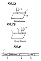
- An optical card disclosed, for example, in PCT/US82/00187 has a large storage as mentioned above. Therefore, when the data are recorded on a plurality of tracks successively, a recording operation is performed by moving the optical card and a recording head relatively and reciprocally.
- Figs. 7A and 7B of the accompanying drawings in which, for example, a data recording operation is performed by moving an optical card 1 reciprocally with respect to a recording head 2, if the data recording operation is performed in both directions, i.e. a normal direction as shown in Fig. 7A and a reverse direction as shown in Fig. 7B, in such a manner that the data are recorded on respective tracks 3 in the same direction using the same modulation method, the data recording direction will vary from track to track. In this case, if a data reading operation is performed in only one direction as usual, the data cannot be read out accurately.
- a method of recording data on a card-like record medium in which a data recording operation is performed by moving the card-like record medium reciprocally in normal and reverse directions with respect to a recording head comprises the steps of: recording data in a predetermined one of normal and reverse directions and in accordance with a predetermined modulation method during the movement in said predetermined direction, and recording data in the other direction in such a manner that the recorded data have the same data recording direction and modulation method as those of the predetermined direction if the data are readout from the same direction as that of the predetermined direction.
- the card-like record medium is moved reciprocally with respect to the recording head, and the recording operation is performed bi-directionally.
- the data recording operation in the normal direction after parallel data to be recorded are converted into serial data and modulated by a predetermined modulation method, the modulated data are recorded on the card-like record medium.
- the parallel data are converted into the serial data in such a manner that the recorded data are to be the same order as that of the normal direction if the data are readout in the same normal direction.
- the converted data are modulated in such a manner that the recorded data are to be the same modulation as that of the normal direction if the data are readout in the same normal direction, and the converted data are recorded on the card-like record medium.
- a main part of the data recording apparatus comprises a buffer memory 11 for storing data to be recorded, a parallel/serial converter 12 for converting parallel data supplied from the buffer memory 11 in a predetermined order into serial data, and a modulator 13 for modulating the converted serial data.
- the modulated data are supplied to a recording head not shown which is moved reciprocally and relatively with respect to an optical card to record the data on the optical card in an optical manner.
- the buffer memory 11, the parallel/serial converter 12 and the modulator 13 are controlled by a recording direction command signal outputted from for example a driving portion for moving the optical card reciprocally or a controlling portion of the driving portion.
- a recording direction shown in Fig. 7A is a normal direction and a recording direction shown in Fig. 7B is a reverse direction, and an operation of the embodiment mentioned above will be explained.
- the buffer memory 11 supplies the data to be recorded in a predetermined order i.e. for example as a parallel data constructed from a top of a data block to the parallel/serial converter 12.
- the parallel data are converted successively into serial bit array from for example a most significant bit (MSB), and are supplied to the modulator 13 as a serial data.
- the serial data are modulated by the known various modulation methods such as a frequency modulation method and a modified frequency modulation method, and the modulated data are supplied to a recording head not shown so as to record the data on the optical card.
- the recording operation in the normal direction mentioned above is the same as that of the known one for the magnetic disc, the optical disc, etc.
- the buffer memory 11 supplies the data to be recorded in the reverse order as that in the normal direction as the parallel data. That is to say, since the data are outputted from the top of the data block in the recording operation of the normal direction, the data are successively outputted from a bottom to the top of the data block in this recording operation of the reverse direction.
- the parallel data are supplied to the parallel/serial converter 12 and are converted in a reverse manner as that in the normal direction into the serial data.
- the data are converted from the most significant bit (MSB) in the recording operation of the normal direction
- the data are successively converted from the least significant bit (LSB) in the recording operation of the reverse direction into the serial data, and the thus converted serial data are supplied to the modulator 13.
- the serial data are converted successively by the modulation method such that the modulated data have the same order when they are readout along the normal direction. Then, the modulated data are supplied to the recording head and are recorded on the optical card.
- modified frequency modulation MFM
- Modified frequency modulation is used for recording on magnetic and optical discs.
- the data modulated by the MFM method can be obtained in such a manner that a window ab is moved bit by bit as shown in Fig. 2A and two bits corresponding to the data of the window ab are selected from a table shown in Fig. 2B.
- Figs. 3A to 3c are schematic views for explaining an operation of the MFM in the normal direction.
- parallel data are supplied as 12H, 34H in this order, wherein H shows that the data 12 is a hexadecimal notation.
- the parallel data 12H are successively converted into serial data from the most significant bit (MSB, and the serial data "00010010" are obtained as shown in Fig. 3B.
- the serial data are modulated by the MFM method to obtain modulation data shown in Fig. 3C.
- Figs. 4A to 4C are schematic views for explaining an operation of the MFM in the reverse direction.
- parallel data are supplied as 34H, 12H in the reverse order as that of the normal direction.
- the parallel data 12H are converted from the least significant bit into the serial data "01001000" as shown in Fig. 4B, and the serial data are modulated by the MFM method illustrated in Fig. 5 to obtain modulation data shown in Fig. 4C.
- the thus obtained modulation data have the same order as that of the normal direction shown in Fig. 3C if viewed from the right side on the figure.
- Fig. 6 shows circuitry incorporating the parallel/serial converter 12 and the modulator 13 shown in Fig. 1.
- the parallel/serial converter 12 comprises a 8 bits bi-directional shift register 13 and a half frequency divider 15, and the modulator 13 comprises a process circuit 16 and a 2 bits shift register 17.
- the parallel data are supplied from the buffer memory 11 (Fig. 1) to the bi-directional shift register 14.
- a recording direction command signal DIR shows the normal direction when it is "1" and the reverse direction when it is "0".
- the modulation clock is supplied for effecting the half frequency divider 15 at a trailing edge thereof and for shifting the parallel data previously loaded to the bi-directional shift register 14 by one bit at a leading edge thereof.
- the shifting operation is performed in a left direction on Fig. 6 when the DIR is"1" and in a right direction on Fig. 6 when the DIR is "0".
- Outputs of the 8 bits bi-directional shift register 14 are supplied to a, b, c, d input terminals of the process circuit 16 respectively and are outputted as Z1 and Z2.
- the processing operation is performed as follows.
- the processed data Z1 and Z2 are supplied to the 2 bits shift register 17 when a frequency divide clock is supplied to the shift register 17 from the half frequency divider 15, and are shifted at the leading edge of the modulation clock to obtain the modulation data. That is to say, when the 8 bits bi-directional shift register 14 is shifted by one bit, the 2 bits shift resister I7 is shifted by two bits.
- the modulation data thus obtained are the data modulated by the normal MFM method when the recording operation is performed in the normal direction, and are the data modulated in the same manner as that of the normal direction if readout from the same reading direction as that of the normal direction.
- the explanation is performed in the case that the modulation method is MFM, but it is possible to use other modulation methods.
- an embodiment of the present invention can be applied not only to recording data on optical cards, as mentioned above, but also on other card-like record mediums such as magnetic cards.
- the data recording operation is performed in the manner that the data are recorded in the same order and the same modulation method when viewed from one direction of the relative and reciprocal movement, it is not necessary to use a recording region for a flag used for the detection of the recording direction, and thus the record medium can be utilized more effectively.
- the data reading apparatus can be made inexpensive in cost. Further, since the detection error of the flag does not occur, the data can be read out more accurately, and thus the reliability of the reading operation can be improved.
Landscapes
- Engineering & Computer Science (AREA)
- Signal Processing (AREA)
- Physics & Mathematics (AREA)
- General Physics & Mathematics (AREA)
- Theoretical Computer Science (AREA)
- Signal Processing For Digital Recording And Reproducing (AREA)
- Optical Recording Or Reproduction (AREA)
Applications Claiming Priority (2)
| Application Number | Priority Date | Filing Date | Title |
|---|---|---|---|
| JP62018715A JPH0828046B2 (ja) | 1987-01-30 | 1987-01-30 | カ−ド状記録媒体へのデ−タ記録方法 |
| JP18715/87 | 1987-01-30 |
Publications (3)
| Publication Number | Publication Date |
|---|---|
| EP0277028A2 true EP0277028A2 (de) | 1988-08-03 |
| EP0277028A3 EP0277028A3 (en) | 1990-08-08 |
| EP0277028B1 EP0277028B1 (de) | 1994-07-20 |
Family
ID=11979353
Family Applications (1)
| Application Number | Title | Priority Date | Filing Date |
|---|---|---|---|
| EP88300764A Expired - Lifetime EP0277028B1 (de) | 1987-01-30 | 1988-01-29 | Verfahren zur Aufzeichnung von Daten auf einem kartenförmigen Aufzeichnungsträger |
Country Status (4)
| Country | Link |
|---|---|
| US (1) | US4962301A (de) |
| EP (1) | EP0277028B1 (de) |
| JP (1) | JPH0828046B2 (de) |
| DE (1) | DE3850679T2 (de) |
Cited By (2)
| Publication number | Priority date | Publication date | Assignee | Title |
|---|---|---|---|---|
| EP0277655A2 (de) * | 1987-02-04 | 1988-08-10 | Olympus Optical Co., Ltd. | Kartenförmiges Aufzeichnungsmedium und Datenaufzeichnungsvorrichtung dafür |
| EP1054392A2 (de) * | 1999-05-21 | 2000-11-22 | Deutsche Thomson-Brandt Gmbh | Optisches Aufzeichnungsmedium |
Families Citing this family (5)
| Publication number | Priority date | Publication date | Assignee | Title |
|---|---|---|---|---|
| US5208792A (en) * | 1987-05-29 | 1993-05-04 | Matsushita Electric Industrial Co., Ltd. | Recording and reproducing apparatus using opto-magneto media |
| JP2835144B2 (ja) * | 1990-05-23 | 1998-12-14 | オリンパス光学工業株式会社 | データ記録装置 |
| MY106779A (en) * | 1990-09-07 | 1995-07-31 | Mitsubishi Heavy Ind Ltd | Magnetic recording method and circuit for toll road ticket. |
| JPH10143866A (ja) * | 1996-11-11 | 1998-05-29 | Nippon Conlux Co Ltd | 光メモリカードのデータ記録方法および装置 |
| JPH11308403A (ja) | 1998-04-22 | 1999-11-05 | Canon Inc | ファクシミリ装置 |
Citations (4)
| Publication number | Priority date | Publication date | Assignee | Title |
|---|---|---|---|---|
| GB2092791A (en) * | 1981-02-02 | 1982-08-18 | Smiths Industries Plc | Record carriers |
| GB2161425A (en) * | 1984-07-10 | 1986-01-15 | Drexler Tech | Debit card |
| EP0197256A2 (de) * | 1985-02-11 | 1986-10-15 | Arthur M. Gerber | System und Verfahren zur Digitalinformationsaufzeichnung |
| FR2580850A1 (fr) * | 1985-04-17 | 1986-10-24 | Canon Kk | Procede d'enregistrement d'informations |
Family Cites Families (6)
| Publication number | Priority date | Publication date | Assignee | Title |
|---|---|---|---|---|
| US4398223A (en) * | 1955-06-14 | 1983-08-09 | Lemelson Jerome H | System for recording video information on a record card |
| US4463444A (en) * | 1981-10-26 | 1984-07-31 | International Business Machines Corporation | Word processing system having a formatting bidirectional printer |
| JPS6174176A (ja) * | 1984-09-19 | 1986-04-16 | Sanyo Electric Co Ltd | デイジタル信号記録再生装置 |
| JP2571205B2 (ja) * | 1985-02-20 | 1997-01-16 | キヤノン株式会社 | 情報記録担体 |
| JPS61242366A (ja) * | 1985-04-19 | 1986-10-28 | Nec Corp | 回転型記録装置 |
| US4825059A (en) * | 1985-10-25 | 1989-04-25 | Canon Kabushiki Kaisha | Apparatus for recording and reproducing information |
-
1987
- 1987-01-30 JP JP62018715A patent/JPH0828046B2/ja not_active Expired - Lifetime
-
1988
- 1988-01-20 US US07/146,247 patent/US4962301A/en not_active Expired - Fee Related
- 1988-01-29 DE DE3850679T patent/DE3850679T2/de not_active Expired - Fee Related
- 1988-01-29 EP EP88300764A patent/EP0277028B1/de not_active Expired - Lifetime
Patent Citations (4)
| Publication number | Priority date | Publication date | Assignee | Title |
|---|---|---|---|---|
| GB2092791A (en) * | 1981-02-02 | 1982-08-18 | Smiths Industries Plc | Record carriers |
| GB2161425A (en) * | 1984-07-10 | 1986-01-15 | Drexler Tech | Debit card |
| EP0197256A2 (de) * | 1985-02-11 | 1986-10-15 | Arthur M. Gerber | System und Verfahren zur Digitalinformationsaufzeichnung |
| FR2580850A1 (fr) * | 1985-04-17 | 1986-10-24 | Canon Kk | Procede d'enregistrement d'informations |
Cited By (4)
| Publication number | Priority date | Publication date | Assignee | Title |
|---|---|---|---|---|
| EP0277655A2 (de) * | 1987-02-04 | 1988-08-10 | Olympus Optical Co., Ltd. | Kartenförmiges Aufzeichnungsmedium und Datenaufzeichnungsvorrichtung dafür |
| EP0277655B1 (de) * | 1987-02-04 | 1997-07-16 | Olympus Optical Co., Ltd. | Kartenförmiges Aufzeichnungsmedium |
| EP1054392A2 (de) * | 1999-05-21 | 2000-11-22 | Deutsche Thomson-Brandt Gmbh | Optisches Aufzeichnungsmedium |
| EP1054392A3 (de) * | 1999-05-21 | 2006-11-08 | Deutsche Thomson-Brandt Gmbh | Optisches Aufzeichnungsmedium |
Also Published As
| Publication number | Publication date |
|---|---|
| DE3850679D1 (de) | 1994-08-25 |
| JPS63187463A (ja) | 1988-08-03 |
| JPH0828046B2 (ja) | 1996-03-21 |
| US4962301A (en) | 1990-10-09 |
| EP0277028A3 (en) | 1990-08-08 |
| EP0277028B1 (de) | 1994-07-20 |
| DE3850679T2 (de) | 1994-11-03 |
Similar Documents
| Publication | Publication Date | Title |
|---|---|---|
| EP0512860A2 (de) | Wiedergabegerät für doppelseitige optische Platten | |
| US4885458A (en) | Card-form recording medium and data recording device therefor | |
| JP2547735B2 (ja) | 情報記録装置 | |
| EP0277028B1 (de) | Verfahren zur Aufzeichnung von Daten auf einem kartenförmigen Aufzeichnungsträger | |
| US5917671A (en) | Recording method and information medium for a plurality of longitudinal track bundles enabling tracking during recording and/or playback of track bundles | |
| US4811321A (en) | Information recording medium | |
| US4853920A (en) | Information recording medium and reproducing method therefor | |
| US4982075A (en) | Information recording medium with track group indicators | |
| JPS63191370A (ja) | カ−ド状記録媒体へのデ−タ記録方法 | |
| EP0227380A1 (de) | Informationsaufzeichnungsträger und Verfahren zur Wiedergabe von Information vom Informationsaufzeichnungsträger | |
| JP2835144B2 (ja) | データ記録装置 | |
| US5233598A (en) | Information recording medium having a plurality of information tracks arranged in a predetermined rectilinear direction | |
| JPS62140244A (ja) | 情報記録担体 | |
| JPS63191371A (ja) | 情報記録担体 | |
| JPS6320766A (ja) | 傾き検知方法 | |
| JPS61216173A (ja) | 情報再生装置 | |
| JPS62140245A (ja) | 情報記録担体 | |
| JPS62140243A (ja) | 情報記録担体 | |
| JPS6260130A (ja) | 情報記録担体 | |
| JPS62137728A (ja) | 情報記録担体 | |
| JPS62162239A (ja) | 情報記録担体 | |
| JPS62145571A (ja) | 情報再生装置 | |
| JPS6260173A (ja) | 情報記録担体 | |
| JPS5818177A (ja) | 磁気デイスク装置における磁気ディスク媒体の検査方法 | |
| JPS6260131A (ja) | 情報記録担体 |
Legal Events
| Date | Code | Title | Description |
|---|---|---|---|
| PUAI | Public reference made under article 153(3) epc to a published international application that has entered the european phase |
Free format text: ORIGINAL CODE: 0009012 |
|
| AK | Designated contracting states |
Kind code of ref document: A2 Designated state(s): DE GB IT |
|
| PUAL | Search report despatched |
Free format text: ORIGINAL CODE: 0009013 |
|
| AK | Designated contracting states |
Kind code of ref document: A3 Designated state(s): DE GB IT |
|
| 17P | Request for examination filed |
Effective date: 19901210 |
|
| 17Q | First examination report despatched |
Effective date: 19920409 |
|
| GRAA | (expected) grant |
Free format text: ORIGINAL CODE: 0009210 |
|
| AK | Designated contracting states |
Kind code of ref document: B1 Designated state(s): DE GB IT |
|
| REF | Corresponds to: |
Ref document number: 3850679 Country of ref document: DE Date of ref document: 19940825 |
|
| ITF | It: translation for a ep patent filed |
Owner name: SOCIETA' ITALIANA BREVETTI S.P.A. |
|
| PLBE | No opposition filed within time limit |
Free format text: ORIGINAL CODE: 0009261 |
|
| STAA | Information on the status of an ep patent application or granted ep patent |
Free format text: STATUS: NO OPPOSITION FILED WITHIN TIME LIMIT |
|
| 26N | No opposition filed | ||
| PGFP | Annual fee paid to national office [announced via postgrant information from national office to epo] |
Ref country code: DE Payment date: 19991231 Year of fee payment: 13 |
|
| PGFP | Annual fee paid to national office [announced via postgrant information from national office to epo] |
Ref country code: GB Payment date: 20000126 Year of fee payment: 13 |
|
| PG25 | Lapsed in a contracting state [announced via postgrant information from national office to epo] |
Ref country code: GB Free format text: LAPSE BECAUSE OF NON-PAYMENT OF DUE FEES Effective date: 20010129 |
|
| GBPC | Gb: european patent ceased through non-payment of renewal fee |
Effective date: 20010129 |
|
| PG25 | Lapsed in a contracting state [announced via postgrant information from national office to epo] |
Ref country code: DE Free format text: LAPSE BECAUSE OF NON-PAYMENT OF DUE FEES Effective date: 20011101 |
|
| PG25 | Lapsed in a contracting state [announced via postgrant information from national office to epo] |
Ref country code: IT Free format text: LAPSE BECAUSE OF NON-PAYMENT OF DUE FEES;WARNING: LAPSES OF ITALIAN PATENTS WITH EFFECTIVE DATE BEFORE 2007 MAY HAVE OCCURRED AT ANY TIME BEFORE 2007. THE CORRECT EFFECTIVE DATE MAY BE DIFFERENT FROM THE ONE RECORDED. Effective date: 20050129 |