EP0276212B1 - Kraftstoff-einspritzsystem - Google Patents
Kraftstoff-einspritzsystem Download PDFInfo
- Publication number
- EP0276212B1 EP0276212B1 EP86905228A EP86905228A EP0276212B1 EP 0276212 B1 EP0276212 B1 EP 0276212B1 EP 86905228 A EP86905228 A EP 86905228A EP 86905228 A EP86905228 A EP 86905228A EP 0276212 B1 EP0276212 B1 EP 0276212B1
- Authority
- EP
- European Patent Office
- Prior art keywords
- factor
- throttle valve
- injection system
- ftc
- fuel
- Prior art date
- Legal status (The legal status is an assumption and is not a legal conclusion. Google has not performed a legal analysis and makes no representation as to the accuracy of the status listed.)
- Expired - Lifetime
Links
- 238000002347 injection Methods 0.000 title claims abstract description 25
- 239000007924 injection Substances 0.000 title claims abstract description 25
- 239000000446 fuel Substances 0.000 title claims abstract description 21
- 230000007704 transition Effects 0.000 claims abstract description 17
- 230000001133 acceleration Effects 0.000 claims abstract description 16
- 238000004364 calculation method Methods 0.000 claims abstract description 7
- 230000001419 dependent effect Effects 0.000 claims description 10
- 238000010586 diagram Methods 0.000 claims description 5
- 238000001514 detection method Methods 0.000 claims description 3
- 230000015572 biosynthetic process Effects 0.000 claims 1
- 239000006227 byproduct Substances 0.000 claims 1
- 230000008859 change Effects 0.000 abstract description 21
- 239000000203 mixture Substances 0.000 abstract description 7
- 238000005259 measurement Methods 0.000 abstract 1
- 206010006895 Cachexia Diseases 0.000 description 2
- 230000008901 benefit Effects 0.000 description 2
- 208000026500 emaciation Diseases 0.000 description 2
- 238000013139 quantization Methods 0.000 description 2
- 230000009467 reduction Effects 0.000 description 2
- 230000001934 delay Effects 0.000 description 1
- 230000003111 delayed effect Effects 0.000 description 1
- 238000011161 development Methods 0.000 description 1
- 230000018109 developmental process Effects 0.000 description 1
- 238000006073 displacement reaction Methods 0.000 description 1
- 230000000694 effects Effects 0.000 description 1
- 238000011156 evaluation Methods 0.000 description 1
- 230000001105 regulatory effect Effects 0.000 description 1
Images

Classifications
-
- F—MECHANICAL ENGINEERING; LIGHTING; HEATING; WEAPONS; BLASTING
- F02—COMBUSTION ENGINES; HOT-GAS OR COMBUSTION-PRODUCT ENGINE PLANTS
- F02D—CONTROLLING COMBUSTION ENGINES
- F02D41/00—Electrical control of supply of combustible mixture or its constituents
- F02D41/02—Circuit arrangements for generating control signals
- F02D41/04—Introducing corrections for particular operating conditions
- F02D41/10—Introducing corrections for particular operating conditions for acceleration
- F02D41/107—Introducing corrections for particular operating conditions for acceleration and deceleration
-
- F—MECHANICAL ENGINEERING; LIGHTING; HEATING; WEAPONS; BLASTING
- F02—COMBUSTION ENGINES; HOT-GAS OR COMBUSTION-PRODUCT ENGINE PLANTS
- F02D—CONTROLLING COMBUSTION ENGINES
- F02D41/00—Electrical control of supply of combustible mixture or its constituents
- F02D41/02—Circuit arrangements for generating control signals
- F02D41/04—Introducing corrections for particular operating conditions
- F02D41/045—Detection of accelerating or decelerating state
Definitions
- the invention is based on a fuel injection system according to the first part of the main claim.
- An injection system is known from FR-A-2 113 745, in which the fuel is supplied as a function of the actuation of the foot pedal (accelerator pedal).
- An electronic signal is derived from the movement and position of the pedals by means of control electronics, which should correspond essentially to the position and speed of the throttle valve.
- control electronics There is no direct connection between throttle valve movement and throttle valve speed and, in particular, with regard to a throttle valve change speed in this known injection system, which is why a highly precise determination of the fuel supply for a transition compensation is not possible. The disadvantages mentioned above can therefore not be avoided.
- An injection system with transition compensation is also known from US-A-4,359,993, in which the fuel supply is influenced by various factors.
- the position and movement of the throttle valve are monitored by means of a throttle valve sensor and the fuel supply is influenced as a function thereof.
- the injection system according to the invention with the features of the main claim has the advantage that there is a transition compensation, which evaluates the throttle valve change speed, and thus the cause of the resulting change in the amount of air is measured, so that the fuel-air mixture composition can be influenced more quickly.
- An advantageous property of the injection system according to the invention is that above a throttle valve change limit speed, the throttle valve change path is additionally taken into account, so that small throttle valve path changes at high throttle valve change speed, which, for. B. occurs when playing with the accelerator at a traffic light, be evaluated differently by the injection system than with a large throttle valve displacement.
- the injection system according to the invention offers a further advantage in that the reduction of the transition compensation during the acceleration enrichment that occurs when accelerating can be carried out with a different reduction constant than in the case of decelerating deceleration that occurs when the gas is removed.
- an intermediate fuel splash threshold which, if exceeded, activates an intermediate splash calculation so that additional fuel can be supplied between the injections.
- FIG. 1 shows a block diagram of the transition compensation of the injection system according to the invention. Basically, the transition compensation can be broken down into three parts.
- the first component 1 determines a factor FÜKMOT by means of arithmetic interpolation via a characteristic curve a which is dependent on the engine temperature T and whose support points can be freely selected.
- the second part 2 determines from a three-dimensional map A a factor FÜK KF which is dependent on the throttle valve angle a and on the speed n, the support points of the map A being freely selectable.
- the values of the FÜK KF factor range between 0.0 and 1.0.
- the third part 3 determines a factor FÜK DEL which is dependent on the throttle valve change speed do / dt and the throttle valve change path.
- the throttle valve change speed chain d ⁇ / dt is determined in the preferred embodiment in a 10 ms grid.
- the maximum tent area for the detection of a transition compensation is 60 ms, with the detection thresholds of the transition compensation for the accelerations enrichment and the delay emaciation are each separately selectable.
- the factor FÜK DEL is determined from a characteristic curve b with the help of the quantity DELTA, which corresponds to the throttle valve change speed da / dt below a throttle valve change limit speed G and, if the throttle valve change limit speed G is exceeded, including the throttle valve change path da according to the equation is calculated, where K represents a correction factor.
- the factor FÜK DEL the values of which are between 0.0 and 1.0, is reduced in regulation 4 in the case of acceleration enrichment and in regulation 5 in the case of decelerating deceleration depending on the ignition pulses Z1.
- the operating point-dependent ignition pulses are interpolated from a motor temperature-dependent characteristic. The regulation can take place at different speeds for the acceleration enrichment and for the deceleration emaciation.
- the factors FÜK MOT , FÜK FK and FÜKoEL are fed to a multiplication point 6 in the case of acceleration enrichment and a multiplication point 7 in the case of decelerating deceleration.
- the factor FP formed in the multiplication point 6 is an add supplied i tion point 8, where the value is added to the factor FP. 1
- the factor FP formed in the multiplication point 7, on the other hand, is reduced in the division point 9 in the preferred embodiment to the fourth part and then fed to a subtraction point 10, where the fourth part of the factor FP is subtracted from the value 1.
- the factor FÜK 1 formed in the addition point 8 and the factor FÜK 2 formed in the subtraction point 10 are fed to a shaft point 11 which identifies the factor FÜK 1 when the acceleration is enriched and the factor FÜK 2 as the transitional compensation factor FÜK in the case of deceleration.
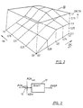
- FIG. 2 shows a three-dimensional map B, which is used to determine the size DELTA.
- the size DELTA is determined as a function of the throttle valve change distance da and the throttle valve change speed da / dt.
- the values of the size DELTA, the throttle valve change speed d ⁇ / dt and the throttle valve change path there are each between 0.0 and 1.0.
- FIG. 3 shows a schematic representation of the intermediate spatter calculation, which is activated when the acceleration increases and when an intermediate spatter threshold is exceeded.
- the intermediate spatter calculation is essentially carried out by a muff multiplication point 12 and a quantization device 13.
- the factor FÜK MOT , the factor FÜK DEL and an intermediate spatter evaluation factor KZW are fed to the multiplication point 12.
- the value calculated in the multiplication point 12 is fed to the quantization device 13, the output of the intermediate splashes ZWSP being able to be regulated such that it takes place, for example, asynchronously to the ignition.
Landscapes
- Engineering & Computer Science (AREA)
- Chemical & Material Sciences (AREA)
- Combustion & Propulsion (AREA)
- Mechanical Engineering (AREA)
- General Engineering & Computer Science (AREA)
- Electrical Control Of Air Or Fuel Supplied To Internal-Combustion Engine (AREA)
- Combined Controls Of Internal Combustion Engines (AREA)
Description
- In allen Kraftstoff-Einspritzsystemen, sowohl digitaler als auch analoger Art, bestehen Einrichtungen, die aufgrund von Luftmengen- oder Luftmassenveränderungen eine Beeinflussung des Kraftstoff-Luft-Gemisches vornehmen. Ursache dieser Luftmassenveränderungen ist die Änderung der Drosselklappenstellung. Bei diesen herkömmlichen Einrichtungen wird demnach zur Berechnung für die Auslösung der Übergangskompensation die Wirkung, d. h. die Änderung der Drosselklappenstellung, herangezogen. Dies hat den Nachteil, daß die Information über eine Änderung des Betriebszustandes zeitlich verzögert erfaßt wird, und damit die Kraftstoffanreicherung oder Kraftstoffabmagerung verspätet erfolgt.
- Aus der FR-A-2 113 745 ist ein Einspritzsystem bekannt, bei dem die Kraftstoffzufuhr in Abhängigkeit von der Betätigung des Fußfahrgebers (Gaspedal) erfolgt. Mittels einer Steuerungselektronik wird aus der Bewegung und Stellung des Fußfahrgebers ein elektrisches Signal abgeleitet, welches im wesentlichen der Stellung und Geschwindigkeit der Drosselklappe entsprechen soll. Ein unmittelbarer Zusammenhang zwischen Drosselklappenbewegung und Drosselklappengeschwindigkeit und insbesondere bezüglich einer Drosselklappenänderungsgeschwindigkeit liegt bei diesem bekannten Einspritzsystem nicht vor, weshalb eine hochgenaue Bestimmung der Kraftstoffzufuhr für eine Übergangskompensation nicht möglich ist. Die oben angegebenen Nachteile können daher auch nicht vermieden werden.
- Auch aus der US-A-4 359 993 ist ein Einspritzsystem mit einer Übergangskompensation bekannt, bei dem die Kraftstoffzufuhr durch verschiedene Faktoren beeinflußt wird. Mittels eines Drosselklappensensors wird die Stellung und Bewegung der Drosselklappe überwacht und in Abhängigkeit davon die Kraftstoffzufuhr beeinflußt.
- Durch Berücksichtigung der Drosselklappengeschwindigkeit und der Drosselklappenstellung kann jedoch nur eine mit unerwünschten Zeitverzögerungen behaftete Steuerung der Kraftstoffzufuhr im Übergangsbereich erreicht werden.
- Das erfindungsgemäße Einspritzsystem mit den Merkmalen des Hauptanspruchs hat den Vorteil, daß eine Übergangskompensation besteht, die die Drosselklappenänderungsgeschwindigkeft auswertet, und somit die Ursache für die sich ergebende Änderung der Luftmenge gemessen wird, so daß die Kraftstoff-Luft-Gemischzusammensetzung schneller beeinflußt werden kann.
- Eine vorteilhafte Eigenschaft des erfindungsgemäßen Einspritzsystems besteht darin, daß oberhalb einer Droselklappenänderungsgrenzgeschwindigkeit zusätzlich der Drosselklappenänderungsweg berücksichtigt wird, so daß kleine Drosselklappenwegänderungen bei hoher Drosselklappenänderungsgeschwindigkeit, was z. B. beim Spielen mit dem Gaspedal an einer Ampel auftritt, anders vom Einspritzsystem bewertet werden als bei gleichzeitig großem Drosselklappenänderungsweg.
- Einen weiteren Vorteil bietet das erfindungsgemäße Einspritzsystem dadurch, daß die Abregelung der Übergangskompensation bei der Beschleunigungsanreicherung, die beim Gasgeben auftritt, mit einer anderen Abregelkonstanten erfolgen kann als bei der Verzögerungsabmagerung, die bei Gaswegnahme einsetzt.
- Für die Beschleunigungsanreicherung existiert zusätzlich eine Kraftstoff-Zwischenspritzerschwelle, die bei Überschreitung eine Zwischenspritzerberechnung aktiviert, so daß zwischen den Einspritzungen zusätzlicher Kraftstoff zugeführt werden kann.
- Durch die in den weiteren abhängigen Ansprüchen aufgeführten Maßnahmen sind vorteilhafte Weiterbildungen und Verbesserungen des im Hauptanspruch angegebenen Einspritzsystems möglich.
- Ausführungsbeispiele der Erfindung sind in der Zeichnung dargesgelft und in der nachfolgenden Beschreibung näher erläutert. Es zeigen:
- Figur 1 ein Blockschaltbild der Übergangskompensation des erfindungsgemäßen Einspritzsystems,
- Figur 2 ein dreidimensionales Kennfeld zur Bestimmung der Größe DELTA und
- Figur 3 eine schematische Darstellung der Zwischenspritzerberechnung.
- Die Figur 1 zeigt ein Blockschaltbild der Übergangskompensation des erfindungsgemäßen Einspritzsystems. Grundsätzlich läßt sich die Übergangskompensation in drei Anteile aufgliedern.
- Der erste Anteil 1 ermittelt durch rechnerische Interpolation über eine von der Motortemperatur T abhängige Kennlinie a, deren Stützstellen frei wählbar sind, einen Faktor FÜKMOT.
- Der zweite Anteil 2 ermittelt aus einem dreidimensionalen Kennfeld A einen vom Drosselklappenwinkel a und von der Drehzahl n abhängigen Faktor FÜKKF, wobei die Stützstellen des Kennfeldes A frei wählbar sind. Die Werte des Faktors FÜKKF bewegen sich dabei zwischen 0,0 und 1,0.
- Der dritte Anteil 3 ermittelt einen von der Drosselklappenänderungsgeschwindigkeit do/dt und dem Drosselklappenänderungsweg da abhängigen Faktor FÜKDEL. Dabei erfolgt die Ermittlung der Drosselklappenänderungsgeschwindigkett dα/dt in der bevorzugten Ausführungsform im 10 ms-Raster. Der maximale Zeltbereich für die Erkennung einer Übergangskompensation beträgt 60 ms, wobei die Erkennungsschwellen der Übergangskompensation für die Beschleunigungsanreicherung und die Verzögerungsabmagerung jeweils getrennt wählbar sind.
- Der Faktor FÜKDEL wird aus einer Kennlinie b mit Hilfe der Größe DELTA bestimmt, die unterhalb einer Drosselklappenänderungsgrenzgeschwindigkeit G der Drosselklappenänderungsgeschwindigkeit da/dt entspricht und bei Überschreiten der Drosselklappenänderungsgrenzgeschwindigkeit G unter Miteinbeziehung des Drosselklappenänderungsweges da gemäß der Gleichung

- Die Faktoren FÜKMOT, FÜKFK und FÜKoEL werden einer Multiplikationsstelle 6 bei Beschleunigungsanreicherung und einer Muftiplikationsstelle 7 bei Verzögerungsabmagerung zugeführt. Der in der Multiplikationsstelle 6 gebildete Faktor FP wird einer Additionsstelle 8 zugeführt, wo der Wert 1 zum Faktor FP hinzuaddiert wird. Der in der Multiplikationsstelle 7 gebildete Faktor FP wird dagegen in der Divisionsstelle 9 bei der bevorzugten Ausführungsform auf den 4. Teil reduziert und danach einer Subtraktionsstelle 10 zugeführt, wo der 4. Teil des Faktors FP vom Wert 1 subtrahiert wird.
- Der in der Additionsstelle 8 gebildete Faktor FÜK1 und der in der Subtraktionsstelle 10 gebildete Faktor FÜK2 werden einer Schaftstelle 11 zugeführt, die bei Beschleunigungsanreicherung den Faktor FÜK1 und bei Verzögerungsabmagerung den Faktor FÜK2 als Übergangskompensationsfaktor FÜK ausweist.
- Die Figur 2 zeigt ein dreidimensionales Kennfeld B, das zur Bestimmung der Größe DELTA dient. Dabei wird die Größe DELTA in Abhängigkeit vom Drosselklappenänderungsweg da und der Drosselklappenänderungsgeschwindigkeit da/dt ermittelt. Die Werte der Größe DELTA, der Drosselklappenänderungsgeschwindigkeit dα/dt und des Drosselklappenänderungsweges da liegen jeweils zwischen 0,0 und 1,0.
- Die Figur 3 zeigt eine schematische Darstellung der Zwischenspritzerberechnung, die bei Beschleunigungsanreicherung und bei Überschreitung einer Zwischenspritzerschwelle aktiviert wird. Die Zwischenspritzerberechnung erfolgt im wesentlichen durch eine Muftiplikationsstelle 12 und einer Quantisierungseinrichtung 13. Der Multiplikationsstelle 12 werden der Faktor FÜKMOT, der Faktor FÜKDEL und ein Zwischenspritzerbewertungsfaktor KZW zugeführt. Der in der Multiplikationsstelle 12 berechnete Wert wird der Quantisierungseinrichtung 13 zugeleitet, wobei die Ausgabe der Zwischenspritzer ZWSP so geregelt werden kann, daß sie beispielsweise asynchron zur Zündung erfolgt.
Claims (10)


Applications Claiming Priority (2)
| Application Number | Priority Date | Filing Date | Title |
|---|---|---|---|
| DE3541731A DE3541731C2 (de) | 1985-11-26 | 1985-11-26 | Kraftstoff-Einspritzsystem |
| DE3541731 | 1985-11-26 |
Publications (2)
| Publication Number | Publication Date |
|---|---|
| EP0276212A1 EP0276212A1 (de) | 1988-08-03 |
| EP0276212B1 true EP0276212B1 (de) | 1990-01-17 |
Family
ID=6286858
Family Applications (1)
| Application Number | Title | Priority Date | Filing Date |
|---|---|---|---|
| EP86905228A Expired - Lifetime EP0276212B1 (de) | 1985-11-26 | 1986-09-19 | Kraftstoff-einspritzsystem |
Country Status (6)
| Country | Link |
|---|---|
| US (1) | US4781163A (de) |
| EP (1) | EP0276212B1 (de) |
| JP (1) | JP2716430B2 (de) |
| AU (1) | AU6375786A (de) |
| DE (2) | DE3541731C2 (de) |
| WO (1) | WO1987003337A1 (de) |
Families Citing this family (8)
| Publication number | Priority date | Publication date | Assignee | Title |
|---|---|---|---|---|
| JP2577210B2 (ja) * | 1986-06-30 | 1997-01-29 | 株式会社ユニシアジェックス | 内燃機関の電子制御燃料噴射装置 |
| JP2532872B2 (ja) * | 1987-05-18 | 1996-09-11 | 日産自動車株式会社 | 内燃機関の燃料制御装置 |
| DE3802444A1 (de) * | 1988-01-28 | 1989-08-10 | Vdo Schindling | Verfahren zur regelung des kraftstoff-luft-verhaeltnisses einer brennkraftmaschine |
| JP2634278B2 (ja) * | 1990-02-16 | 1997-07-23 | 三菱電機株式会社 | 内燃機関燃料噴射装置 |
| JPH04303146A (ja) * | 1991-03-30 | 1992-10-27 | Mazda Motor Corp | エンジンの燃料制御装置 |
| JP3073591B2 (ja) * | 1992-03-17 | 2000-08-07 | マツダ株式会社 | エンジンの制御装置 |
| US5492102A (en) * | 1994-05-04 | 1996-02-20 | Chrysler Corporation | Method of throttle fuel lean-out for internal combustion engines |
| JP3908385B2 (ja) | 1998-06-03 | 2007-04-25 | 株式会社ケーヒン | 内燃エンジンの制御装置 |
Family Cites Families (17)
| Publication number | Priority date | Publication date | Assignee | Title |
|---|---|---|---|---|
| GB1305612A (de) * | 1970-11-10 | 1973-02-07 | ||
| US3720191A (en) * | 1971-01-25 | 1973-03-13 | Bendix Corp | Acceleration enrichment circuitry for electronic fuel system |
| US4159697A (en) * | 1976-10-04 | 1979-07-03 | The Bendix Corporation | Acceleration enrichment circuit for fuel injection system having potentiometer throttle position input |
| JPS5517674A (en) * | 1978-07-26 | 1980-02-07 | Hitachi Ltd | Electronic engine controller |
| US4359993A (en) * | 1981-01-26 | 1982-11-23 | General Motors Corporation | Internal combustion engine transient fuel control apparatus |
| JPS58160520A (ja) * | 1981-12-31 | 1983-09-24 | オ−ビタル・エンジン・カンパニイ・プロプライエタリ・リミテツド | 内燃機関用燃料噴射装置 |
| JPS58144633A (ja) * | 1982-02-23 | 1983-08-29 | Toyota Motor Corp | 内燃機関の電子制御燃料噴射方法 |
| GB2116333B (en) * | 1982-03-01 | 1987-01-14 | Honda Motor Co Ltd | Fuel supply control system for internal combustion engines |
| US4490792A (en) * | 1982-04-09 | 1984-12-25 | Motorola, Inc. | Acceleration fuel enrichment system |
| JPS58214629A (ja) * | 1982-06-09 | 1983-12-13 | Japan Electronic Control Syst Co Ltd | 内燃機関の電子制御燃料噴射装置 |
| JPS58220935A (ja) * | 1982-06-16 | 1983-12-22 | Honda Motor Co Ltd | 内燃エンジンの加速時燃料供給制御方法 |
| JPS58220934A (ja) * | 1982-06-16 | 1983-12-22 | Honda Motor Co Ltd | 内燃エンジンの加速時燃料供給制御方法 |
| US4635200A (en) * | 1983-06-16 | 1987-01-06 | Nippon Soken, Inc. | System for controlling air-fuel ratio in an internal combustion engine |
| JPS603458A (ja) * | 1983-06-22 | 1985-01-09 | Honda Motor Co Ltd | 内燃エンジンの燃料供給制御方法 |
| US4616619A (en) * | 1983-07-18 | 1986-10-14 | Nippon Soken, Inc. | Method for controlling air-fuel ratio in internal combustion engine |
| JPS60116836A (ja) * | 1983-11-29 | 1985-06-24 | Nippon Soken Inc | 内燃機関の空燃比制御装置 |
| JPS6158940A (ja) * | 1984-08-29 | 1986-03-26 | Mazda Motor Corp | エンジンの空燃比制御装置 |
-
1985
- 1985-11-26 DE DE3541731A patent/DE3541731C2/de not_active Expired - Fee Related
-
1986
- 1986-09-19 AU AU63757/86A patent/AU6375786A/en not_active Abandoned
- 1986-09-19 DE DE8686905228T patent/DE3668350D1/de not_active Expired - Lifetime
- 1986-09-19 US US07/090,246 patent/US4781163A/en not_active Expired - Lifetime
- 1986-09-19 EP EP86905228A patent/EP0276212B1/de not_active Expired - Lifetime
- 1986-09-19 JP JP61504880A patent/JP2716430B2/ja not_active Expired - Lifetime
- 1986-09-19 WO PCT/DE1986/000380 patent/WO1987003337A1/de not_active Ceased
Also Published As
| Publication number | Publication date |
|---|---|
| DE3541731A1 (de) | 1987-05-27 |
| DE3668350D1 (de) | 1990-02-22 |
| JP2716430B2 (ja) | 1998-02-18 |
| AU6375786A (en) | 1987-07-01 |
| DE3541731C2 (de) | 1994-08-18 |
| JPS63503397A (ja) | 1988-12-08 |
| US4781163A (en) | 1988-11-01 |
| WO1987003337A1 (fr) | 1987-06-04 |
| EP0276212A1 (de) | 1988-08-03 |
Similar Documents
| Publication | Publication Date | Title |
|---|---|---|
| DE69431335T2 (de) | Verfahren zum Bestimmen der Übergänge von einem Stationären in einen Übergangsbetriebszustand bei einer Brennkraftmaschine | |
| DE3703645C2 (de) | Verfahren zur Beeinflussung der Fahrgeschwindigkeit eines Kraftfahrzeugs und Einrichtung zur Durchführung des Verfahrens | |
| DE3311892C2 (de) | ||
| DE3924923C2 (de) | ||
| DE3901109C2 (de) | Adaptive Regeleinrichtung für das Luft-Kraftstoff-Verhältnis einer Brennkraftmaschine | |
| DE2749369C2 (de) | Regelsystem für ein Stellglied im zusatzluftzuführenden Umgehungskanal einer Drosselklappe bei Brennkraftmaschinen | |
| DE68912499T2 (de) | Methode und Vorrichtung zum Steuern der Kraftstoffeinspritzung für Brennkraftmaschinen. | |
| DE3135148C2 (de) | ||
| DE3120667A1 (de) | Steuersystem fuer eine fremdgezuendete brennkraftmaschine | |
| DE3433042C2 (de) | ||
| DE3838054C2 (de) | ||
| DE3541731C2 (de) | Kraftstoff-Einspritzsystem | |
| EP0375710B1 (de) | Einstellsystem (steuerungs- und/oder regelungssystem) für kraftfahrzeuge | |
| EP0406246A1 (de) | Verfahren zur vermeidung eines zu grossen motorschleppmoments. | |
| DE3429672C2 (de) | ||
| DE3872260T2 (de) | Verfahren zur beschleunigungsanreicherung bei kraftstoffeinspritzsystemen. | |
| DE3627419A1 (de) | Verfahren zur regelung der kraftstoffeinspritzung | |
| DE3151131A1 (de) | "verfahren und vorrichtung zur brennstoff-einspritzmengenregelung bei einer brennkraftmaschine" | |
| DE3542119A1 (de) | Anordnung zum regeln der leerlaufdrehzahl eines kraftfahrzeugmotors | |
| EP0502849B1 (de) | Elektronisches steuersystem für die kraftstoffzumessung bei einer brennkraftmaschine | |
| DE3825945C2 (de) | Vorrichtung zur Verbesserung nachteiliger Wirkungen von Ablagerungen innerhalb einer Brennkraftmaschine auf die Motorregelung | |
| DE3441070C2 (de) | ||
| DE68903345T2 (de) | Elektronisches motor-steuerungsverfahren. | |
| DE3235497C2 (de) | ||
| EP0140152A2 (de) | Vorrichtung zur Steuerung des Schubbetriebs einer Brennkraftmaschine |
Legal Events
| Date | Code | Title | Description |
|---|---|---|---|
| PUAI | Public reference made under article 153(3) epc to a published international application that has entered the european phase |
Free format text: ORIGINAL CODE: 0009012 |
|
| 17P | Request for examination filed |
Effective date: 19880427 |
|
| AK | Designated contracting states |
Kind code of ref document: A1 Designated state(s): DE FR IT |
|
| 17Q | First examination report despatched |
Effective date: 19890118 |
|
| GRAA | (expected) grant |
Free format text: ORIGINAL CODE: 0009210 |
|
| AK | Designated contracting states |
Kind code of ref document: B1 Designated state(s): DE FR IT |
|
| REF | Corresponds to: |
Ref document number: 3668350 Country of ref document: DE Date of ref document: 19900222 |
|
| ET | Fr: translation filed | ||
| ITF | It: translation for a ep patent filed | ||
| PLBE | No opposition filed within time limit |
Free format text: ORIGINAL CODE: 0009261 |
|
| STAA | Information on the status of an ep patent application or granted ep patent |
Free format text: STATUS: NO OPPOSITION FILED WITHIN TIME LIMIT |
|
| 26N | No opposition filed | ||
| ITTA | It: last paid annual fee | ||
| PGFP | Annual fee paid to national office [announced via postgrant information from national office to epo] |
Ref country code: FR Payment date: 20030819 Year of fee payment: 18 |
|
| PGFP | Annual fee paid to national office [announced via postgrant information from national office to epo] |
Ref country code: DE Payment date: 20031029 Year of fee payment: 18 |
|
| PG25 | Lapsed in a contracting state [announced via postgrant information from national office to epo] |
Ref country code: DE Free format text: LAPSE BECAUSE OF NON-PAYMENT OF DUE FEES Effective date: 20050401 |
|
| PG25 | Lapsed in a contracting state [announced via postgrant information from national office to epo] |
Ref country code: FR Free format text: LAPSE BECAUSE OF NON-PAYMENT OF DUE FEES Effective date: 20050531 |
|
| REG | Reference to a national code |
Ref country code: FR Ref legal event code: ST |
|
| PG25 | Lapsed in a contracting state [announced via postgrant information from national office to epo] |
Ref country code: IT Free format text: LAPSE BECAUSE OF NON-PAYMENT OF DUE FEES;WARNING: LAPSES OF ITALIAN PATENTS WITH EFFECTIVE DATE BEFORE 2007 MAY HAVE OCCURRED AT ANY TIME BEFORE 2007. THE CORRECT EFFECTIVE DATE MAY BE DIFFERENT FROM THE ONE RECORDED. Effective date: 20050919 |