US4635200A - System for controlling air-fuel ratio in an internal combustion engine - Google Patents
System for controlling air-fuel ratio in an internal combustion engine Download PDFInfo
- Publication number
- US4635200A US4635200A US06/619,210 US61921084A US4635200A US 4635200 A US4635200 A US 4635200A US 61921084 A US61921084 A US 61921084A US 4635200 A US4635200 A US 4635200A
- Authority
- US
- United States
- Prior art keywords
- air
- engine
- fuel ratio
- value
- fuel
- Prior art date
- Legal status (The legal status is an assumption and is not a legal conclusion. Google has not performed a legal analysis and makes no representation as to the accuracy of the status listed.)
- Expired - Lifetime
Links
Images


Classifications
-
- F—MECHANICAL ENGINEERING; LIGHTING; HEATING; WEAPONS; BLASTING
- F02—COMBUSTION ENGINES; HOT-GAS OR COMBUSTION-PRODUCT ENGINE PLANTS
- F02D—CONTROLLING COMBUSTION ENGINES
- F02D41/00—Electrical control of supply of combustible mixture or its constituents
- F02D41/02—Circuit arrangements for generating control signals
- F02D41/14—Introducing closed-loop corrections
- F02D41/1438—Introducing closed-loop corrections using means for determining characteristics of the combustion gases; Sensors therefor
- F02D41/1477—Introducing closed-loop corrections using means for determining characteristics of the combustion gases; Sensors therefor characterised by the regulation circuit or part of it,(e.g. comparator, PI regulator, output)
- F02D41/148—Using a plurality of comparators
-
- F—MECHANICAL ENGINEERING; LIGHTING; HEATING; WEAPONS; BLASTING
- F02—COMBUSTION ENGINES; HOT-GAS OR COMBUSTION-PRODUCT ENGINE PLANTS
- F02B—INTERNAL-COMBUSTION PISTON ENGINES; COMBUSTION ENGINES IN GENERAL
- F02B77/00—Component parts, details or accessories, not otherwise provided for
- F02B77/08—Safety, indicating, or supervising devices
-
- F—MECHANICAL ENGINEERING; LIGHTING; HEATING; WEAPONS; BLASTING
- F02—COMBUSTION ENGINES; HOT-GAS OR COMBUSTION-PRODUCT ENGINE PLANTS
- F02D—CONTROLLING COMBUSTION ENGINES
- F02D41/00—Electrical control of supply of combustible mixture or its constituents
- F02D41/24—Electrical control of supply of combustible mixture or its constituents characterised by the use of digital means
- F02D41/2406—Electrical control of supply of combustible mixture or its constituents characterised by the use of digital means using essentially read only memories
- F02D41/2425—Particular ways of programming the data
- F02D41/2429—Methods of calibrating or learning
- F02D41/2451—Methods of calibrating or learning characterised by what is learned or calibrated
- F02D41/2454—Learning of the air-fuel ratio control
-
- F—MECHANICAL ENGINEERING; LIGHTING; HEATING; WEAPONS; BLASTING
- F02—COMBUSTION ENGINES; HOT-GAS OR COMBUSTION-PRODUCT ENGINE PLANTS
- F02D—CONTROLLING COMBUSTION ENGINES
- F02D41/00—Electrical control of supply of combustible mixture or its constituents
- F02D41/24—Electrical control of supply of combustible mixture or its constituents characterised by the use of digital means
- F02D41/2406—Electrical control of supply of combustible mixture or its constituents characterised by the use of digital means using essentially read only memories
- F02D41/2425—Particular ways of programming the data
- F02D41/2429—Methods of calibrating or learning
- F02D41/2441—Methods of calibrating or learning characterised by the learning conditions
Definitions
- the present invention relates to a system for controlling the air-fuel ratio in an internal combustion engine provided with fuel injectors, the system being operated by a feedback control to maintain a constant air-fuel ratio under various engine operating conditions.
- Japanese Unexamined Patent Publication (Kokai) No. 56-6034 discloses an air-fuel ratio control system for an internal combustion engine in which a basic fuel-requirement signal is generated in response to certain engine operating parameters, including engine temperature, which indicate the fuel requirements of the engine while running in a stable condition.
- This prior art also discloses a means for detecting the operating condition of the engine during a transient state and indicating a required increase in an engine output, and means for generating a signal for intensifying the air-fuel ratio correction in accordance with the sensed engine temperature and the sensed operating condition of the engine during the transient state.
- This air-fuel ratio correction signal has an initial value determined by the engine temperature and the sensed engine transient state, and this value is increased toward 1.0 at a speed determined by the temperature of the engine.
- the prior art also includes a means for supplying fuel to the engine in accordance with the above-mentioned basic signal and the intensifying air-fuel ratio correction signal, so that a required amount of fuel is supplied to the engine at both the stable running condition and the transient state.
- This system can maintain an optimum or predetermined air-fuel ratio not only in the stable running condition but also in the transient state of the engine, thus obtaining an optimum engine operation.
- a disadvantage of this prior art system is that it is not provided with a means for compensating the changes in the characteristics of the engine which occur after the engine has been in operation for a prolonged period, such as oil or carbon deposits in the valve clearance, in the injector nozzle, or at the back of the intake valve. These deposits originate mainly from oil or carbon residues caused by combustion.
- the characteristics of an engine also change when different blends of gasoline are used.
- a system having no means of compensating for such changes in characteristics is disadvantaged in that the air-fuel mixture will often become lean during acceleration, causing a rough acceleration and an inferior drivability, when an inferior blend of gasoline is used or when the engine characteristics are changed after a prolonged period of operation.
- the correct blend of gasoline is used, the fuel consumption efficiency is decreased, or the amount of toxic emissions is increased, by a rich air-fuel mixture during acceleration.
- An object of the present engine is to provide a system capable of overcoming the above-mentioned difficulties encountered in the prior art.
- Another object of the present invention is to provide a system capable of maintaining a constant air-fuel ratio despite changes in the engine operating conditions caused by oil or carbon deposits, by prolonged use, by different blends of gasoline, or by other factors stemming from differences in tolerances in individual mass-produced engines and components such as an air-flow meter.
- a further object of the present invention is to provide a system capable of maintaining the best possible fuel consumption-efficiency and automobile drivability.
- FIG. 1 shows the difference in the air-fuel ratio caused when deposits exist and when deposits do not exist
- FIG. 2 shows the difference in the air-fuel ratio when the engine is operating on gasoline blended for summer use and for winter use
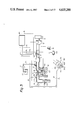
- FIG. 3 shows an embodiment of the system of the present invention
- FIGS. 4a and 4b are a block diagram of the control circuit shown in FIG. 4;
- FIGS. 5(a), (b), (c), (d), (f) are timing charts concerning the various engine operating factors
- FIG. 6 is a flow chart of a main routine stored as a program in the computer
- FIG. 7 is a flow chart showing details of the feedback control routine shown in FIG. 6;
- FIG. 8 is a flow chart showing details of the routine for calculating deviation of the air-fuel ratio at a transient state of the engine
- FIG. 9 shows a routine for calculating an acceleration correction factor
- FIG. 10 is a flow chart of an interruption routine for calculating the fuel amount to be injected
- FIG. 11 is a flow chart of a routine for calculating a basic fuel amount to be injected
- FIG. 12a is a flow chart showing another embodiment used for calculating the deviation of the air-fuel ratio at the transient state
- FIG. 12b is a continuation of FIG. 12a;
- FIG. 13 is a flow chart showing another embodiment for calculating the acceleration correction factor K
- FIGS. 14(a)-14(e) and 15(a)-15(e) show changes of various factors shown in FIGS. 12a, 12b, and 13;
- FIGS. 16(A) and 16(B) illustrate an effect of the learning control of the present invention when the blend of gasoline is changed.
- FIG. 17 shows a modification of the embodiment used for calculating the acceleration correction factor shown in FIG. 13.
- the air-fuel ratio change in the prior art is illustrated in accordance with the lapse of time wherein an acceleration is effected at the time t acc .
- a certain off-set or deviation of the air-fuel ratio from a target air-fuel ratio value (A/F) 0 which may be equal to the stoichiometric air-fuel ratio, is caused at acceleration.
- the air-fuel ratio changes as shown by curve m 1 .
- the air-fuel ratio changes as shown by curve m 2 . It will be clear from the figure that, in the prior art, a large offset of the air-fuel ratio occurs during acceleration when the engine contains deposits.
- the deviation of an air-fuel ratio during acceleration also occurs when the injector is clogged, because there is no way of compensating for the change in air-fuel ratio during acceleration, despite the fact that the air-fuel ratio deviation from the target value during the stable running condition of the engine is automatically corrected by the feedback mechanism.
- the above deviation is also caused by differences in tolerances in individual mass-produced engines or components such as air-flow meters, or by changes in the engine characteristics stemming from prolonged use.
- FIG. 2 shows the changes in the air-fuel ratio caused by using different blends of gasoline. This problem is brought about by factors similar to those previously mentioned regarding production differences, and by changes in the gasoline blends produced for summer and winter operation, i.e., different blends of gasoline have different volatilities.
- the volatility of a gasoline blend is evaluated by its Reid vapor pressure or distillation property values. Gasoline produced by a certain maker can have a Reid vapor pressure value of between 0.5 kg/cm 2 to 0.86 kg/cm 2 , and a distillation temperature differing by 10%, e.g., between 40° C. to 50° C., depending on the season of the year. These differences in the gasoline cause the changes in the air-fuel ratio as shown in FIG. 2.
- FIG. 2 shows the changes in the air-fuel ratio caused by using different blends of gasoline.
- curve n 1 shows the air-fuel ratio needed for a gasoline blended for summer use
- curve n 2 shows that needed for a gasoline blended for winter use.
- the air-fuel ratio is shown as deviating toward the lean side, the air-fuel ratio may also deviate toward the rich side.
- FIG. 3 shows an internal combustion engine having an air cleaner 10. Downstream of the air cleaner 10, an air-flow meter 12 and a throttle valve 14 are arranged in an intake pipe 17 of the engine. A fuel injection nozzle 16 is opened to the intake pipe 17 at a position near to an engine body.
- the engine body has a cylinder block 18 and a cylinder head 20 fixed to the cylinder block 18.
- a piston 22 is arranged in the cylinder block 18, with a combustion chamber 24 formed above the piston 22.
- a spark plug 25 is mounted to the cylinder head 20 so that a spark gap 25' of the spark plug 25 is opened to the combustion chamber 24.
- the combustion chamber 24 is connected to the intake pipe 17 by way of an intake valve 26, so that a combustible mixture from the intake pipe 17 is introduced into the combustion chamber 24 when the intake valve 26 is opened.
- the combustion chamber 24 is also connected to an exhaust manifold 28 via an exhaust valve 29, so that the resultant exhaust gas is forced out of the combustion chamber 24 and into the exhaust manifold 28 when the exhaust valve 29 is opened.
- a fuel tank 30 is connected to the fuel injector 16 via a fuel pump 32 and a fuel delivery pipe 34.
- the engine is further provided with an ignition system having a distributor 36 and an ignition coil 38, which system is connected to the spark plug 25.
- a control circuit 40 controls the fuel injection. Sensors are connected to the control circuit 40 to detect the various engine operating conditions.
- the air-flow meter 12 produces a signal indicating the amount of air introduced into the engine, which signal is input to the control circuit 40 via a line l 1 .
- An O 2 sensor 42 provided on the exhaust manifold 28 produces a signal indicating the air-fuel ratio, which signal is input to the control circuit 40 via a line l 2 .
- a pair of crank signal sensors 44 and 46 are mounted on a casing 361 of the distributer 36 in such a manner that they face a detecting piece 363 mounted on a distributor shaft 362 of the distributor 36.
- One of the sensors 44 detects the rotational speed of the engine, and produces a plurality of pulses during every one rotation of the engine which are input to the control circuit 40 via a line l 3 .
- the other sensor 46 detects a predetermined position of the piston 22 of a predetermined one cylinder of the engine, and produces a pulse at every one rotation of the engine, which pulse is input to the control circuit 40 via a line l 4 .
- a temperature sensor 50 is mounted to the cylinder block 18 in such a manner that it is in contact with a cooling water in the cylinder block 18, to produce a signal indicating the temperature of the cooling water, which signal is input to the control circuit 40 via a line l 5 .
- a throttle sensor 51 is connected to the throttle valve 14, to produce a signal indicating the opening of the throttle valve 14, which signal is input to the control circuit 40 via a line l 6 .
- control circuit 40 calculates the amount of fuel to be injected by processing the signals from the above-mentioned sensors, and produces a signal which is input to the fuel injector 16 via a line l 7 , thus operating the injector 16.
- control circuit 40 is constructed as shown in FIGS. 4a and 4b. As shown in the figures, control circuit 40 has an analog multiplexer 54, to which the air-flow meter 12, the water temperature sensor 50, and the throttle sensor 51 are connected together with other analog type sensors (not shown) not directly related with the present invention.
- the analog multiplexer 54 is connected to an analog-to-digital (A/D) converter 56, wherein the analog signals are changed to digital signals.
- A/D analog-to-digital
- the crank angle sensor 44 which produces a plurality of pulses per one engine rotation, is connected to a velocity-signal-forming circuit 58, which is a counter circuit for counting the number of pulses from the sensor 44.
- the velocity-signal-forming circuit 58 is connected to an input port 59.
- This sensor 44 is also connected to a timing generator circuit 60 together with the crank angle sensor 46, for producing a single pulse per every one rotation of the engine.
- the timing generator circuit 60 is connected to a central processing unit (CPU) 62 for permitting an interruption to start.
- the O 2 sensor 42 is connected to a comparator circuit 66 at one input.
- a reference level generator circuit 67 is connected to the other input of the comparator circuit 66.
- the output of the comparator circuit 66 is connected to the input port 59.
- the comparator circuit 66 has a shaping circuit 66' and a delay circuit 66" connected between its input and the O 2 sensor.
- the analog multiplexer 54, the A/D converter 56, and the input port 56 are connected, via a bus 72, to the CPU 62, a read only memory (ROM) 70, and a random access memory (RAM) 68, which are constitutional elements of a microcomputer system.
- the CPU 62 operates, in response to a clock signal generator 74, to receive signals from the sensors and to calculate the amount of fuel to be injected.
- the bus 72 is connected to an output port 76 for receiving the calculated result from the CPU 62.
- the output port 76 is connected to the fuel injector 16 via a down counter 77 and a bistable circuit 78.
- FIG. 5 is a timing chart showing various factors of the operation of the system according to the present invention.
- the CPU 62 calculates, as will be fully described later, an amount of fuel to be injected. This amount is determined when the engine is in a stable running condition by the product of the basic fuel amount t p (corresponding to the time from the opening of the injector 16 to the closing of the injector 16) and a feedback correction factor FAF.
- the O 2 sensor outputs an electric signal corresponding to the air-fuel ratio; i.e., the output voltage level is alternately made high or low in accordance with the air-fuel ratio value.
- the high level voltage corresponds to an air-fuel ratio value which is smaller than the stoichiometric air-fuel ratio, i.e., a rich air-fuel mixture.
- the low level voltage corresponds to an air-fuel ratio value which is larger than the stoichiometric ratio, i.e., a lean air-fuel mixture.
- the comparator circuit 66 then compares the signal from the O 2 sensor with a fixed reference level. When the signal level is higher than the fixed level, the comparator 66 issues a logic signal "1", indicating that the air-fuel mixture is rich.
- the comparator 66 issues a logic signal "0", indicating that the air-fuel mixture is lean.
- a signal is obtained with a value which alternately changes between “0” and “1” in accordance with the air-fuel ratio value, as shown in FIG. 5(c).
- the condition at the O 2 sensor 42 changes from a "0" signal to a "1" signal, because the O 2 sensor 42 has detected an air-fuel ratio value smaller than the stoichiometric air-fuel ratio, i.e., a rich air-fuel mixture, and therefore an amount of fuel to be injected from the fuel injector 16 is to be decreased.
- the feedback correction factor FAF to be multiplied with the basic fuel amount t p to be injected is decreased, as shown by a line l 0 in FIG. 5(d). Because of the decrease in the correction factor FAF, the amount of fuel to be injected is also decreased, so that the air-fuel ratio value is increased toward the stoichiometric air-fuel ratio.
- the condition at the O 2 sensor 42 changes from a "1" signal to a "0" signal, because the O 2 sensor 42 now detects an air-fuel ratio value higher than the stoichiometric air-fuel ratio, i.e., a lean air-fuel mixture, and an amount of fuel to be injected is then to be increased.
- the feedback correction factor FAF is now increased, as shown by a line l 1 in FIG. 5(d). Because of the increase in the correction factor FAF, the amount of fuel to be injected is also increased, so that the air-fuel ratio value is decreased toward the stoichiometric ratio (A/F) 0 .
- the condition at the O 2 sensor 42 again changes from “0" to "1", because the O 2 sensor 42 detects an air-fuel ratio lower than the predetermined air-fuel ratio value (A/F) 0 .
- the correction factor FAF is then decreased, as shown by a line l 2 .
- the engine operation changes from the stable condition to an acceleration condition at a time t 3 (see FIG. 5(a)).
- this acceleration condition the engine requires an increased amount of fuel to be injected.
- the feedback control is not sufficient to quickly respond to the fuel requirement, and an acceleration correction factor to be multiplied is therefore employed to increase the amount of fuel to be injected, and thus maintain a constant air-fuel ratio during the acceleration.
- introduction of the acceleration correction factor alone is not sufficient to fully correct the air-fuel ratio during the acceleration to the target value (A/F) 0 , based on the various factors occurring while the engine is in the transient state; which includes oil or carbon deposits or different blends of gasoline, as already mentioned.
- the air-fuel ratio value during acceleration may move away from the target value and toward the lean side, as shown by a line X in FIG. 5(b), which phenomenon is known as a "lean spike", or toward the rich side, as shown by X', which is known as a "rich spike”.
- the present invention is intended to prevent such deviation of the air-fuel ratio from occurring, by the following principles.
- the feedback correction factor FAF when there is a deviation of the air-fuel ratio from the target value, such as that shown by the line X or X' in FIG. 5(b), the feedback correction factor FAF should have a value which differs from a value obtained during the stable running condition. This attains a difference of ⁇ A/F over the average f(A/F) of the feedback correction factor during the stable condition. This difference is taken as a measurement of the deviation of the air-fuel ratio to the target air-fuel ratio value (A/F) 0 , caused by the transient condition of the engine.
- control of the acceleration correction factor K obtained in accordance with the change of the air-fuel ratio ⁇ F/A permits the system to effect a "learning control" in such a manner that the deviation of the air-fuel ratio from the target value is gradually decreased as the engine experiences the subsequent series of accelerations. In this way, the air-fuel ratio is finally maintained at the target value, as shown by a line Y in FIG. 5(b), during the acceleration.
- FIG. 6 illustrates the main routine effected by the control circuit 40.
- the computer enters a calculation routine. It then proceeds to point 200, where an initialize operation is effected to clear or set the registers in the CPU 62, the RAM 68, and the input and output ports 59 and 76.
- a feedback control of the fuel injection operation is effected so that the air-fuel ratio is controlled to the target value, i.e., stoichiometric air-fuel ratio.
- a deviation or offset of the air-fuel ratio value at the time the engine enters into a transient state from the stable running condition is detected.
- an acceleration correction factor K is calculated. The program then proceeds to point 400 and is ready to repeat the above-mentioned procedures.
- the feedback control routine 400 is shown in detail in FIG. 7.
- the CPU 62 inputs the data from the O 2 sensor and determines whether or not the signal level is "1" or "0", i.e., whether the air-fuel mixture is rich or not. If the answer is "no", then the signal from the O 2 sensor 42 is for a lean air-fuel mixture.
- the program proceeds to point 404 where it is determined whether or not a flag fO 2 is 0.
- This flag fO 2 is reset (0) when the signal from the O 2 sensor changes from "1" (rich) to "0" (lean).
- the flag fO 2 is set (1) when the signal from the O 2 sensor changes from "0" (lean) to "1" (rich).
- a "no" answer at point 404 means that the O 2 sensor 42 has output, at the preceding cycle, a "1" signal, and that the air-fuel ratio has just changed from rich to lean, as realized at time t 1 in FIG. 5(d).
- the flag fO 2 is reset (0).
- a flag fS is set. This flag fS indicates whether or not the air-fuel ratio signal has changed from "1" to "0" or "0" to "1". That is, flag fS is set (1) at every skip control, and is reset (0) during the normal feedback control, as shown by lines l 0 , l 1 , and l 2 in FIG. 5(d).
- a feedback correction factor FAF is stored in an area of the RAM 68, f(A/F) i .
- This f(A/F) i value corresponds to a value of the feedback correction factor FAF at the time t 1 (FIG. 5(d)).
- the feedback correction factor FAF is incremented by 10. This means that the feedback correction factor is abruptly increased, as shown by the curve s 1 at the time t 1 , where the air-fuel ratio is changed from a rich condition (1) to a lean condition (0).
- an effective feedback control of the air-fuel ratio to the target value (A/F) 0 is attained.
- the program proceeds to point 414, where the skip indicating flag fS is reset.
- the feedback correction factor is incremented by 1.
- the feedback correction factor FAF begins a moderate increase, as shown by the line l 1 in FIG. 5(d). Note: the number 10 shown at point 412 and the number 1 shown at point 416 are only examples illustrating that the former number at the skip point (time t 1 ) is larger than the latter number. There is no particular significance attached to the actual value of these numbers.
- the program then proceeds to point 420, where the flag fO 2 is set (1), to point 422 where the skip indicating flag fS is set (1), and to point 424 where the value of the feedback correction factor FAF is stored in the area f(A/F) i of the RAM 68.
- the feedback correction factor FAF is decremented by 10. That is, the feedback correction factor FAF is abruptly decreased, as shown by curve s 2 at the time t 2 . Because of this "skip" control of the feedback correction factor FAF, the air-fuel ratio is quickly controlled to the target value (A/F).
- the answer at point 418 is "yes". That is, since the flag fO 2 is set (1) at point 420 during the preceding cycle, the result of the discrimination at point 418 is "yes", so that the program proceeds to point 426, where the skip indicating flag fS is reset (0).
- the feedback correction factor is decremented by 1, and the feedback correction factor FAF begins to moderately decrease, as shown by the line l 2 in FIG. 5(d). Note: the number 1 is only an example and is determined so that the feedback correction factor is moderately decreased, as shown by the line l 2 in FIG. 5(d).
- FIG. 8 is a detailed flow chart of the routine in block 500 shown in FIG. 6.
- This routine is for detecting any air-fuel ratio deviation or offset occurring when the engine condition changes from stable running to a transient condition, i.e., at acceleration.
- the flag fS is set.
- the answer is "no" at point 502
- the program then bypasses the routine shown in FIG. 8.
- An average value f(A/F) of the feedback correction factor FAF during idling may be used as a reference value of the air-fuel ratio, whether or not offset of the air-fuel ratio has occurred during the engine transient condition including acceleration.
- the CPU 62 selects the analog multiplexer 54 so that the signal from the throttle sensor 51 is input to the A/D converter 56 for converting the analog signal from the throttle sensor 51 into a digital signal indicating the opening of the throttle valve 14. The CPU 62 then compares the detected data with the preset data corresponding to the throttle opening for idling.
- a "yes" answer at point 504 means that the engine is in an idling condition, and allows the program to proceed to point 506.
- a value of a feedback correction factor FAF at this skip cycle stored in the area f(A/F) i of the RAM 68 (see point 410 or 424 of FIG. 8) and a value of a feedback correction factor FAF at the preceding skip cycle stored in the area f(A/F) i-1 of the RAM 68 (see point 508) are averaged.
- the average value is stored in an area f(A/F) of the RAM 68.
- This value f(A/F) is taken as the mean value of the feedback correction factor FAF during the idling or stable condition (FIG. 5(d)).
- the data in the RAM area f(A/F) i is moved to the RAM area f(A/F) i-1 , and is taken as the value of the feedback correction factor at the preceding skip cycle during the following skip cycle (see point 506).
- the feedback correction factor begins to increase, as shown by the line l 3 , at the time t 3 wherein the O 2 sensor signal changes from "1" (rich) to "0" (lean).
- the O 2 sensor signal changes from "0" (lean) to "1" (rich) at time t 4 .
- This value of the feedback correction factor FAF at the time t 4 is stored in the RAM area f(A/F) i at point 512.
- An average value of the feedback correction factor at the two skip points preceding the skip at t 4 is stored in the RAM area f(A/F) as an average air-fuel ratio during the stable running condition.
- the value ⁇ A/F calculated at point 512 is considered as to be an offset in the air-fuel ratio caused by a change in the engine operation from a stable running condition to a transient state.
- a "yes" at point 514 means that offset has not occurred, and the program proceeds to point 508, explained previously.
- a “no” at point 514 means that some offset in the air-fuel ratio from the target value is occurring due to the acceleration.
- the program proceeds to point 516, where it is determined whether or not ⁇ A/F is larger than zero.
- a “yes” at point 516 means that an offset of the air-fuel ratio toward the lean side, i.e., a "lean spike", has occurred.
- the value of the acceleration counter DPC is incremented.
- a “no” at point 516 means that an offset of the air-fuel ratio toward the rich side, i.e., a "rich spike", has occurred.
- the program proceeds to point 520, where the acceleration counter DPC is decremented.
- FIG. 9 is a concept of the routine 600, shown in FIG. 6, for calculating the acceleration correction factor.
- a correction factor K is calculated from the value of the acceleration counter DPC obtained at point 518 or 520, together with the temperature T of the cooling water sensed by the water temperature sensor 50 and the time t lapsed.
- the initial maximum value is mainly determined by the value of the acceleration counter DPC which can have, after the attainment of learning control shown in FIG. 8, a value for maintaining a substantially unchanged air-fuel ratio, as shown in line Y in FIG.
- the area of the RAM 68 in which the learned value of the acceleration counter DPC is stored may be constituted as a nonvolatile type RAM, allowing the engine to maintain the stabilized acceleration condition newly stated after the engine is stopped.
- FIG. 10 is flow chart of a routine for effecting fuel injection, which is an interruption routine effected at every one rotation of the engine.
- the crank angle sensor 44 issues a signal indicating every one rotation of the engine.
- the CPU 62 starts the interruption routine described in FIG. 10.
- the CPU 62 inputs the data of the rotational speed of the engine Ne from the input port 59 connected to the Ne forming circuit 58.
- the CPU 62 selects the analog multiplexer 54 so that the signal from the air-flow meter 12 is input to the A/D converter 56.
- the A/D converter converts the analog signal from the air-flow meter 12 indicating an intake air amount Qa to a digital signal which is input to the internal resistor in the CPU 62.
- the CPU 62 selects the analog multiplexer 54 so that the signal from the engine water temperature sensor 50 is input to the A/D converter 56.
- the A/D converter 56 converts the analog signal indicating the temperature of the engine cooling water T into a digital signal which is input to the CPU 62.
- the CPU 62 calculates the intake air amount Qa divided by the rotational speed of the engine Ne.
- the program then proceeds to point 8025, where a basic amount of fuel to be injected t p is calculated through the values Qa/Ne and T.
- the obtained data of the basic injected fuel amount t p is stored in a predetermined area of the RAM 68.
- the program then proceeds from point 802 to point 804 to calculate ⁇ ', which is a product of t p and FAF.
- ⁇ ' is a product of t p and FAF.
- a "no" at point 806 means that the engine is in a stable running condition, and the program then proceeds to point 808, where the value ⁇ ' is moved to the RAM area ⁇ .
- the program proceeds to point 810, where the value ⁇ ' multiplied by the acceleration correction factor K is moved to the RAM area ⁇ .
- the CPU 62 sets the down counter 77 to this value ⁇ .
- the down counter 77 When the down counter 77 is set, it starts to count down after receiving a trigger signal issued from the bus 72, which also triggers the bistable circuit 78, so that the fuel injector 16 starts the fuel injection into the intake pipe 17. When the countdown is completed, the down counter 77 issues a pulse to reset the bistable circuit 78, so that the fuel injector 16 is closed. As a result, the calculated amount of fuel, corresponding to the value ⁇ is injected into the intake pipe 17, and the engine maintains the target air-fuel ratio value irrespective of whether the engine condition includes acceleration.
- FIGS. 12a and 12b are a flow chart showing another embodiment used for effecting the routine 500, shown in FIG. 6, for detecting air-fuel ratio deviation when the engine changes from a stable running condition to a transient condition, including acceleraton or deceleration.
- the program proceeds to point 552 where the values of the feedback correction factor FAF at the preceding four skip points, f(A/F) i-4 , f(A/F) i-3 , f(A/F) i-2 , and f(A/F) i-2 , are averaged.
- the obtained value is moved to the RAM area f(A/F).
- the program proceeds to point 556 in FIG. 12 where the value of the feedback correction factor FAF at this skip point and stored in the RAM area f(A/F) i is subtracted from the mean value in the RAM area f(A/F) obtained at point 552. The difference is stored in the RAM area ⁇ A/F.
- a "yes” answer means that an air-fuel ratio deviation larger than 5% has originated from a “lean spike” during acceleration or deceleration.
- the value of the counter DPC is incremented, as described with reference to FIG. 9 at point 518.
- a "no" answer at point 558 causes the program to proceed to point 564, where it is determined whether or not the air-fuel ratio deviation detected at point 556 is smaller than 5%.
- a "yes” answer causes the program to proceed to point 566, where it is determined whether or not the engine is under acceleration. If the answer at point 566 is "yes”, the air-fuel ratio deviation larger than 5% is considered to have originated from a "rich spike” during the transient state of the engine. Therefore, at the following point 568, the value of the counter DPC is decremented, as described with reference to point 520 in FIG. 9 in the previous embodiment.
- FIG. 13 is a flow chart showing the details of the routine 600, shown in FIG. 6, used for calculating an acceleration correction factor K.
- an amount of intake air per one rotation of the engine, Qa/Ne is calculated.
- the acceleration correction routine does not enter into the calculation before the lapse of the predetermined time interval.
- an acceleration correction coefficient a and a rounding or loosening coefficient b are taken as a function of the value of the air-fuel ratio correcting counter DPC.
- the ROM 70 is provided with maps of the acceleration correction coefficient a and the rounding coefficient b with respect to various values of the DPC.
- the CPU calculates the values a and b at one value of the DPC, calculated at point 518 or 520 of FIG. 9, from the maps. That is, the acceleration correction factor a and the rounding coefficient b are calculated in accordance with the deviation of the air-fuel ratio from the target value (A/F) 0 at acceleration.
- (Qa/Ne) is a value of the ratio of the intake air amount to the rotation speed during the preceding cycle
- Qa/Ne-(Qa/Ne) j-1 is an actual increase in the ratio at this cycle from the preceding cycle. Since this actual increase is divided by b, (Qa/Ne) has a value smaller than the value actually attained by Qa/Ne. Thus, a loosened change of (Qa/Ne) j is obtained.
- an acceleration correction factor K is calculated by the following equation.
- T is a temperature of the engine cooling water sensed by the engine cooling water temperature sensor 50.
- FIG. 14 illustrates how the throttle opening TH, Qa/Ne, (Qa/Ne) j , K, and fuel injection time ⁇ change after the start of the acceleration.
- the throttle opening TH is abruptly increased at the start of the acceleration, as shown by (a).
- Qa/Ne attains a curve which corresponds to the change in the throttle opening, as shown by (b).
- the rate of the change in (Qa/Ne) j which is determined by equation (1), is loosened when compared with the change in Qa/Ne, as shown by (c).
- An acceleration correction factor K determined by equation (2), changes as shown by FIG. 14(d).
- the factor K abruptly attains the maximum value and slowly decreases in accordance with the lapse of time.
- the time period ⁇ for opening the fuel injector 16, which corresponds to the amount of fuel to be injected, is changed as shown by (e).
- FIG. 16 the effect of the learning control according to the present invention is illustrated.
- a change of the air-fuel ratio with regard to the time lapse during which the engine is under acceleration is shown when a summer blend gasoline (temperature for distillating 10% of gasoline, 47° C., Reid vapor pressure 0.72 kg/cm 2 ) is used is shown in FIG. 16(A).
- the air-fuel ratio w is substantially maintained without being changed.
- FIG. 17 is a modification of FIG. 13.
- the embodiment shown in FIG. 17 differs from the embodiment of FIG. 13 in that the determination at point 652' is effected by each one rotation of the engine, instead of detecting the time interval as at point 652 in FIG. 13. That is, the calculation of Qa/Ne is effected in synchronism with the engine rotation.
- a calculation of (Qa/Ne) synchronous with the engine rotation permits the number of engine combustion cycles under the fuel control by the correction factor K, regardless of the engine rotation number, to be maintained at substantially the same figure during the same acceleration condition. As a result, a constant air-fuel ratio during the transient state may be maintained at all operational conditions of the engine.
- the calculation of the acceleration correction coefficient is determined by Qa/Ne and its loosened amount.
- other values such as the intake pipe vacuum, throttle opening, and their corresponding loosened amounts, may be used in place of Qa/Ne and its loosened amount, to obtain the correction factor.
Landscapes
- Engineering & Computer Science (AREA)
- Chemical & Material Sciences (AREA)
- Combustion & Propulsion (AREA)
- Mechanical Engineering (AREA)
- General Engineering & Computer Science (AREA)
- Electrical Control Of Air Or Fuel Supplied To Internal-Combustion Engine (AREA)
Abstract
Description
(Qa/Ne).sub.).sub.j =(Qa/Ne).sub.j-1 +{Qa/Ne-(Qa/Ne).sub.j-i }/b (1)
K={Qa/Ne-(Qa/Ne).sub.j }×a×T (2)
Claims (3)
Applications Claiming Priority (4)
| Application Number | Priority Date | Filing Date | Title |
|---|---|---|---|
| JP58-106697 | 1983-06-16 | ||
| JP10669783A JPS601344A (en) | 1983-06-16 | 1983-06-16 | Fuel injection control device for internal-combustion engine |
| JP13526083A JPS6027746A (en) | 1983-07-26 | 1983-07-26 | Air-fuel ratio controlling method for internal- combustion engine |
| JP58-135260 | 1983-07-26 |
Publications (1)
| Publication Number | Publication Date |
|---|---|
| US4635200A true US4635200A (en) | 1987-01-06 |
Family
ID=26446811
Family Applications (1)
| Application Number | Title | Priority Date | Filing Date |
|---|---|---|---|
| US06/619,210 Expired - Lifetime US4635200A (en) | 1983-06-16 | 1984-06-11 | System for controlling air-fuel ratio in an internal combustion engine |
Country Status (1)
| Country | Link |
|---|---|
| US (1) | US4635200A (en) |
Cited By (15)
| Publication number | Priority date | Publication date | Assignee | Title |
|---|---|---|---|---|
| US4741311A (en) * | 1986-04-24 | 1988-05-03 | Honda Giken Kogyo Kabushiki Kaisha | Method of air/fuel ratio control for internal combustion engine |
| US4781163A (en) * | 1985-11-26 | 1988-11-01 | Robert Bosch Gmbh | Fuel injection system |
| US4872117A (en) * | 1984-11-30 | 1989-10-03 | Suzuki Jidosha Kogyo Kabushiki Kaisha | Apparatus for controlling an air-fuel ratio in an internal combustion engine |
| US4899280A (en) * | 1987-04-08 | 1990-02-06 | Hitachi, Ltd. | Adaptive system for controlling an engine according to conditions categorized by driver's intent |
| US4976242A (en) * | 1989-01-27 | 1990-12-11 | Toyota Jidosha Kabushiki Kaisha | Fuel injection control device of an engine |
| US4981122A (en) * | 1989-01-27 | 1991-01-01 | Toyota Jidosha Kabushiki Kaisha | Fuel injection control device of an engine |
| US4991559A (en) * | 1989-01-24 | 1991-02-12 | Toyota Jidosha Kabushiki Kaisha | Fuel injection control device of an engine |
| US4996644A (en) * | 1987-01-22 | 1991-02-26 | Mitsubishi Denki Kabushiki Kaisha | Air-fuel ratio control system for use in internal combustion engine |
| US5018494A (en) * | 1989-02-23 | 1991-05-28 | Toyota Jidosha Kabushiki Kaisha | Idling speed control device of an engine |
| DE4120062A1 (en) * | 1990-06-28 | 1992-01-09 | Suzuki Motor Co | INTERNAL COMBUSTION ENGINE WITH A CONTROL CIRCUIT FOR THE ENLARGEMENT OF THE AIR-FUEL MIXTURE DURING THE ACCELERATION |
| US5099941A (en) * | 1988-09-20 | 1992-03-31 | Mitsubishi Jidosha Kogyo Kabushiki Kaisha | Cruise control device for motor vehicles |
| US5148369A (en) * | 1987-08-08 | 1992-09-15 | Mitsubishi Denki Kabushiki Kaisha | Air-fuel control apparatus for an internal combustion engine |
| GB2282468A (en) * | 1993-10-04 | 1995-04-05 | Ford Motor Co | A fuel controller with air/fuel transient compensation |
| US5408975A (en) * | 1993-05-05 | 1995-04-25 | Polaris Industries L.P. | Priming control system for fuel injected engines |
| US5551410A (en) * | 1995-07-26 | 1996-09-03 | Ford Motor Company | Engine controller with adaptive fuel compensation |
Citations (8)
| Publication number | Priority date | Publication date | Assignee | Title |
|---|---|---|---|---|
| US4130095A (en) * | 1977-07-12 | 1978-12-19 | General Motors Corporation | Fuel control system with calibration learning capability for motor vehicle internal combustion engine |
| US4235204A (en) * | 1979-04-02 | 1980-11-25 | General Motors Corporation | Fuel control with learning capability for motor vehicle combustion engine |
| US4270503A (en) * | 1979-10-17 | 1981-06-02 | General Motors Corporation | Closed loop air/fuel ratio control system |
| US4322800A (en) * | 1979-04-04 | 1982-03-30 | Nippondenso Co., Ltd. | Method of reducing fuel consumption rate in internal combustion engines |
| JPS58133435A (en) * | 1982-02-02 | 1983-08-09 | Toyota Motor Corp | Electronically controlled fuel injection method of internal-combustion engine |
| JPS58133434A (en) * | 1982-02-02 | 1983-08-09 | Toyota Motor Corp | Electronically controlled fuel injection method of internal-combustion engine |
| US4469074A (en) * | 1981-07-13 | 1984-09-04 | Nippondenso Co., Ltd. | Electronic control for internal combustion engine |
| US4481928A (en) * | 1981-07-06 | 1984-11-13 | Toyota Jidosha Kabushiki Kaisha | L-Jetronic fuel injected engine control device and method smoothing air flow meter overshoot |
-
1984
- 1984-06-11 US US06/619,210 patent/US4635200A/en not_active Expired - Lifetime
Patent Citations (8)
| Publication number | Priority date | Publication date | Assignee | Title |
|---|---|---|---|---|
| US4130095A (en) * | 1977-07-12 | 1978-12-19 | General Motors Corporation | Fuel control system with calibration learning capability for motor vehicle internal combustion engine |
| US4235204A (en) * | 1979-04-02 | 1980-11-25 | General Motors Corporation | Fuel control with learning capability for motor vehicle combustion engine |
| US4322800A (en) * | 1979-04-04 | 1982-03-30 | Nippondenso Co., Ltd. | Method of reducing fuel consumption rate in internal combustion engines |
| US4270503A (en) * | 1979-10-17 | 1981-06-02 | General Motors Corporation | Closed loop air/fuel ratio control system |
| US4481928A (en) * | 1981-07-06 | 1984-11-13 | Toyota Jidosha Kabushiki Kaisha | L-Jetronic fuel injected engine control device and method smoothing air flow meter overshoot |
| US4469074A (en) * | 1981-07-13 | 1984-09-04 | Nippondenso Co., Ltd. | Electronic control for internal combustion engine |
| JPS58133435A (en) * | 1982-02-02 | 1983-08-09 | Toyota Motor Corp | Electronically controlled fuel injection method of internal-combustion engine |
| JPS58133434A (en) * | 1982-02-02 | 1983-08-09 | Toyota Motor Corp | Electronically controlled fuel injection method of internal-combustion engine |
Cited By (19)
| Publication number | Priority date | Publication date | Assignee | Title |
|---|---|---|---|---|
| US4872117A (en) * | 1984-11-30 | 1989-10-03 | Suzuki Jidosha Kogyo Kabushiki Kaisha | Apparatus for controlling an air-fuel ratio in an internal combustion engine |
| US4781163A (en) * | 1985-11-26 | 1988-11-01 | Robert Bosch Gmbh | Fuel injection system |
| US4741311A (en) * | 1986-04-24 | 1988-05-03 | Honda Giken Kogyo Kabushiki Kaisha | Method of air/fuel ratio control for internal combustion engine |
| US4996644A (en) * | 1987-01-22 | 1991-02-26 | Mitsubishi Denki Kabushiki Kaisha | Air-fuel ratio control system for use in internal combustion engine |
| US4899280A (en) * | 1987-04-08 | 1990-02-06 | Hitachi, Ltd. | Adaptive system for controlling an engine according to conditions categorized by driver's intent |
| US5099429A (en) * | 1987-04-08 | 1992-03-24 | Hitachi, Ltd. | Adaptive system for controlling an engine according to conditions categorized by driver's intent |
| US5148369A (en) * | 1987-08-08 | 1992-09-15 | Mitsubishi Denki Kabushiki Kaisha | Air-fuel control apparatus for an internal combustion engine |
| US5099941A (en) * | 1988-09-20 | 1992-03-31 | Mitsubishi Jidosha Kogyo Kabushiki Kaisha | Cruise control device for motor vehicles |
| US4991559A (en) * | 1989-01-24 | 1991-02-12 | Toyota Jidosha Kabushiki Kaisha | Fuel injection control device of an engine |
| US4976242A (en) * | 1989-01-27 | 1990-12-11 | Toyota Jidosha Kabushiki Kaisha | Fuel injection control device of an engine |
| US4981122A (en) * | 1989-01-27 | 1991-01-01 | Toyota Jidosha Kabushiki Kaisha | Fuel injection control device of an engine |
| US5018494A (en) * | 1989-02-23 | 1991-05-28 | Toyota Jidosha Kabushiki Kaisha | Idling speed control device of an engine |
| US5134982A (en) * | 1990-06-28 | 1992-08-04 | Suzuki Motor Corporation | Distinction device of fuel in use for internal combustion engine |
| DE4120062A1 (en) * | 1990-06-28 | 1992-01-09 | Suzuki Motor Co | INTERNAL COMBUSTION ENGINE WITH A CONTROL CIRCUIT FOR THE ENLARGEMENT OF THE AIR-FUEL MIXTURE DURING THE ACCELERATION |
| US5408975A (en) * | 1993-05-05 | 1995-04-25 | Polaris Industries L.P. | Priming control system for fuel injected engines |
| GB2282468A (en) * | 1993-10-04 | 1995-04-05 | Ford Motor Co | A fuel controller with air/fuel transient compensation |
| US5503134A (en) * | 1993-10-04 | 1996-04-02 | Ford Motor Company | Fuel controller with air/fuel transient compensation |
| GB2282468B (en) * | 1993-10-04 | 1998-08-12 | Ford Motor Co | A fuel controller with air/fuel transient compensation |
| US5551410A (en) * | 1995-07-26 | 1996-09-03 | Ford Motor Company | Engine controller with adaptive fuel compensation |
Similar Documents
| Publication | Publication Date | Title |
|---|---|---|
| US4635200A (en) | System for controlling air-fuel ratio in an internal combustion engine | |
| US4658787A (en) | Method and apparatus for engine control | |
| US4403584A (en) | Method and apparatus for optimum control for internal combustion engines | |
| US4886030A (en) | Method of and system for controlling fuel injection rate in an internal combustion engine | |
| US5058552A (en) | Engine control apparatus | |
| GB2217045A (en) | Fuel injection control system for an automotive engine | |
| US5003953A (en) | Transient fuel injection | |
| US5186149A (en) | System for controlling fuel supply for internal combustion engine | |
| WO2003006808A1 (en) | 4-stroke engine control device and control method | |
| US4573443A (en) | Non-synchronous injection acceleration control for a multicylinder internal combustion engine | |
| JPH04214947A (en) | Torque fluctuation control device for internal combustion engine | |
| US5255655A (en) | Fuel injection system for an internal combustion engine | |
| US4563994A (en) | Fuel injection control apparatus | |
| US4457283A (en) | Electronically controlled fuel injection system | |
| US5003956A (en) | Electronic fuel injection control system for a multi-fuel internal combustion engine and method therefore | |
| US5497752A (en) | Device for controlling fuel injection of an internal combustion engine | |
| JP2917600B2 (en) | Fuel injection control device for internal combustion engine | |
| US5577482A (en) | Fuel supply system for internal combustion engines | |
| US4502448A (en) | Method for controlling control systems for internal combustion engines immediately after termination of fuel cut | |
| US5590633A (en) | Fuel injection control system for engine | |
| US5261376A (en) | Two cycle internal combuston engine with multiple cylinder fuel injection | |
| US4520784A (en) | Method of and apparatus for controlling fuel injection | |
| EP0429460B1 (en) | A fuel injection system for an internal combustion engine | |
| JPH0623554B2 (en) | Engine throttle control device | |
| GB2121215A (en) | Automatic control of the fuel supply to an internal combustion engine immediately after termination of fuel cut |
Legal Events
| Date | Code | Title | Description |
|---|---|---|---|
| AS | Assignment |
Owner name: TOYOTA JIDOSHA KABUSHIKI KAISHA, 1, TOYOTA-CHO, TO Free format text: ASSIGNMENT OF ASSIGNORS INTEREST.;ASSIGNORS:EGAMI, TSUNEYUKI;SAITO, TSUTOMU;KOHAMA, TOKIO;AND OTHERS;REEL/FRAME:004272/0363 Effective date: 19840529 Owner name: NIPPON SOKEN, INC., 14, IWAYA, SHIMOHASUMI-CHO, NI Free format text: ASSIGNMENT OF ASSIGNORS INTEREST.;ASSIGNORS:EGAMI, TSUNEYUKI;SAITO, TSUTOMU;KOHAMA, TOKIO;AND OTHERS;REEL/FRAME:004272/0363 Effective date: 19840529 |
|
| STCF | Information on status: patent grant |
Free format text: PATENTED CASE |
|
| FEPP | Fee payment procedure |
Free format text: PAYOR NUMBER ASSIGNED (ORIGINAL EVENT CODE: ASPN); ENTITY STATUS OF PATENT OWNER: LARGE ENTITY |
|
| FPAY | Fee payment |
Year of fee payment: 4 |
|
| FPAY | Fee payment |
Year of fee payment: 8 |
|
| FPAY | Fee payment |
Year of fee payment: 12 |