EP0273447B1 - Tonsignalerzeugungsvorrichtung mit einem digitalen Filter - Google Patents
Tonsignalerzeugungsvorrichtung mit einem digitalen Filter Download PDFInfo
- Publication number
- EP0273447B1 EP0273447B1 EP19870119324 EP87119324A EP0273447B1 EP 0273447 B1 EP0273447 B1 EP 0273447B1 EP 19870119324 EP19870119324 EP 19870119324 EP 87119324 A EP87119324 A EP 87119324A EP 0273447 B1 EP0273447 B1 EP 0273447B1
- Authority
- EP
- European Patent Office
- Prior art keywords
- tone
- filter
- address signal
- orders
- data
- Prior art date
- Legal status (The legal status is an assumption and is not a legal conclusion. Google has not performed a legal analysis and makes no representation as to the accuracy of the status listed.)
- Expired - Lifetime
Links
- 230000007274 generation of a signal involved in cell-cell signaling Effects 0.000 title claims description 46
- 230000004044 response Effects 0.000 claims description 45
- 238000001914 filtration Methods 0.000 claims description 5
- 238000005070 sampling Methods 0.000 description 80
- 230000015654 memory Effects 0.000 description 56
- 239000011295 pitch Substances 0.000 description 28
- 238000010586 diagram Methods 0.000 description 15
- 238000001228 spectrum Methods 0.000 description 12
- 238000000034 method Methods 0.000 description 11
- 238000010276 construction Methods 0.000 description 8
- 238000012952 Resampling Methods 0.000 description 6
- 230000002238 attenuated effect Effects 0.000 description 6
- 230000008901 benefit Effects 0.000 description 5
- 238000006243 chemical reaction Methods 0.000 description 5
- 230000000694 effects Effects 0.000 description 5
- 238000012545 processing Methods 0.000 description 5
- 238000001308 synthesis method Methods 0.000 description 4
- 230000000994 depressogenic effect Effects 0.000 description 3
- 238000013461 design Methods 0.000 description 3
- 238000009825 accumulation Methods 0.000 description 2
- 230000003111 delayed effect Effects 0.000 description 2
- 230000006870 function Effects 0.000 description 2
- 230000006872 improvement Effects 0.000 description 2
- 238000004519 manufacturing process Methods 0.000 description 2
- 230000001360 synchronised effect Effects 0.000 description 2
- 230000002411 adverse Effects 0.000 description 1
- 239000003086 colorant Substances 0.000 description 1
- 238000005520 cutting process Methods 0.000 description 1
- 230000001934 delay Effects 0.000 description 1
- 238000001514 detection method Methods 0.000 description 1
- 238000003780 insertion Methods 0.000 description 1
- 230000037431 insertion Effects 0.000 description 1
- 230000004048 modification Effects 0.000 description 1
- 238000012986 modification Methods 0.000 description 1
- 238000002360 preparation method Methods 0.000 description 1
- 230000009467 reduction Effects 0.000 description 1
Images


Classifications
-
- G—PHYSICS
- G10—MUSICAL INSTRUMENTS; ACOUSTICS
- G10H—ELECTROPHONIC MUSICAL INSTRUMENTS; INSTRUMENTS IN WHICH THE TONES ARE GENERATED BY ELECTROMECHANICAL MEANS OR ELECTRONIC GENERATORS, OR IN WHICH THE TONES ARE SYNTHESISED FROM A DATA STORE
- G10H7/00—Instruments in which the tones are synthesised from a data store, e.g. computer organs
- G10H7/02—Instruments in which the tones are synthesised from a data store, e.g. computer organs in which amplitudes at successive sample points of a tone waveform are stored in one or more memories
- G10H7/04—Instruments in which the tones are synthesised from a data store, e.g. computer organs in which amplitudes at successive sample points of a tone waveform are stored in one or more memories in which amplitudes are read at varying rates, e.g. according to pitch
-
- G—PHYSICS
- G10—MUSICAL INSTRUMENTS; ACOUSTICS
- G10H—ELECTROPHONIC MUSICAL INSTRUMENTS; INSTRUMENTS IN WHICH THE TONES ARE GENERATED BY ELECTROMECHANICAL MEANS OR ELECTRONIC GENERATORS, OR IN WHICH THE TONES ARE SYNTHESISED FROM A DATA STORE
- G10H1/00—Details of electrophonic musical instruments
- G10H1/02—Means for controlling the tone frequencies, e.g. attack or decay; Means for producing special musical effects, e.g. vibratos or glissandos
- G10H1/06—Circuits for establishing the harmonic content of tones, or other arrangements for changing the tone colour
- G10H1/12—Circuits for establishing the harmonic content of tones, or other arrangements for changing the tone colour by filtering complex waveforms
- G10H1/125—Circuits for establishing the harmonic content of tones, or other arrangements for changing the tone colour by filtering complex waveforms using a digital filter
-
- G—PHYSICS
- G10—MUSICAL INSTRUMENTS; ACOUSTICS
- G10H—ELECTROPHONIC MUSICAL INSTRUMENTS; INSTRUMENTS IN WHICH THE TONES ARE GENERATED BY ELECTROMECHANICAL MEANS OR ELECTRONIC GENERATORS, OR IN WHICH THE TONES ARE SYNTHESISED FROM A DATA STORE
- G10H2250/00—Aspects of algorithms or signal processing methods without intrinsic musical character, yet specifically adapted for or used in electrophonic musical processing
- G10H2250/055—Filters for musical processing or musical effects; Filter responses, filter architecture, filter coefficients or control parameters therefor
- G10H2250/111—Impulse response, i.e. filters defined or specified by their temporal impulse response features, e.g. for echo or reverberation applications
- G10H2250/115—FIR impulse, e.g. for echoes or room acoustics, the shape of the impulse response is specified in particular according to delay times
-
- G—PHYSICS
- G10—MUSICAL INSTRUMENTS; ACOUSTICS
- G10H—ELECTROPHONIC MUSICAL INSTRUMENTS; INSTRUMENTS IN WHICH THE TONES ARE GENERATED BY ELECTROMECHANICAL MEANS OR ELECTRONIC GENERATORS, OR IN WHICH THE TONES ARE SYNTHESISED FROM A DATA STORE
- G10H2250/00—Aspects of algorithms or signal processing methods without intrinsic musical character, yet specifically adapted for or used in electrophonic musical processing
- G10H2250/055—Filters for musical processing or musical effects; Filter responses, filter architecture, filter coefficients or control parameters therefor
- G10H2250/111—Impulse response, i.e. filters defined or specified by their temporal impulse response features, e.g. for echo or reverberation applications
- G10H2250/121—IIR impulse
-
- G—PHYSICS
- G10—MUSICAL INSTRUMENTS; ACOUSTICS
- G10H—ELECTROPHONIC MUSICAL INSTRUMENTS; INSTRUMENTS IN WHICH THE TONES ARE GENERATED BY ELECTROMECHANICAL MEANS OR ELECTRONIC GENERATORS, OR IN WHICH THE TONES ARE SYNTHESISED FROM A DATA STORE
- G10H2250/00—Aspects of algorithms or signal processing methods without intrinsic musical character, yet specifically adapted for or used in electrophonic musical processing
- G10H2250/131—Mathematical functions for musical analysis, processing, synthesis or composition
- G10H2250/145—Convolution, e.g. of a music input signal with a desired impulse response to compute an output
-
- G—PHYSICS
- G10—MUSICAL INSTRUMENTS; ACOUSTICS
- G10H—ELECTROPHONIC MUSICAL INSTRUMENTS; INSTRUMENTS IN WHICH THE TONES ARE GENERATED BY ELECTROMECHANICAL MEANS OR ELECTRONIC GENERATORS, OR IN WHICH THE TONES ARE SYNTHESISED FROM A DATA STORE
- G10H2250/00—Aspects of algorithms or signal processing methods without intrinsic musical character, yet specifically adapted for or used in electrophonic musical processing
- G10H2250/541—Details of musical waveform synthesis, i.e. audio waveshape processing from individual wavetable samples, independently of their origin or of the sound they represent
- G10H2250/545—Aliasing, i.e. preventing, eliminating or deliberately using aliasing noise, distortions or artifacts in sampled or synthesised waveforms, e.g. by band limiting, oversampling or undersampling, respectively
Definitions
- This invention relates to a tone signal generation device performing removal of an aliasing noise and tone color control utilizing a digital filter operation and, more particularly, to a tone signal generation device capable of performing a digital filter operation of a good quality with a relatively simple hardware structure.
- a digital filter is utilized for controlling the tone color of a digital tone signal or removing noise.
- a tone synthesis method called a pitch non-synchronizing type tone synthesis method according to which a tone signal is synthesized by conducting sampling with a constant sampling frequency irrespective of the frequency of a tone to be synthesized
- the frequency of the tone and the sampling frequency are generally in non-integer ratio relation and, accordingly, as will be apparent from the sampling theorem, an aliasing noise which is not harmonic with the tone frequency tends to be generated and removal of such aliasing noise becomes necessary.
- a tone signal it has been proposed to cause a tone signal to pass through a digital filter of characteristics capable of removing the aliasing noise (US-A-4,701,956).
- US-A-4 036 096 describes a tone signal generator capable of producing a desired waveshape by previously storing basic amplitudes obtained by sampling one period of the waveshape at a coarse interval and calculating amplitudes with a fine interval between the basic amplitudes.
- the basic amplitudes are sequentially produced at a coarse interval in response to an integer portion of the input data.
- a function is produced in response to a fraction portion of the input data.
- Waveshape amplitudes are interpolated between the basic amplitudes.
- a waveshape generator of the memory reading type is disclosed.
- a waveshape memory stores sample values of a wave, each value being represented by an integral address.
- a coefficient memory stores coefficients for nth order interpolation. Unknown intermediate sample values not stored in the waveshape memory represented by non-integral addresses are approximated by multiplication of stored sample values of the waveshape and corresponding coefficient values on the basis of nth order interpolation.
- the tone signal generation device of the present invention has the features of claim 1,8 or 9, respectively.
- the tone signal generation device comprises address signal generation means for generating an address signal consisting of an integer section and a decimal section, the value of said address signal changing at a rate corresponding to tone pitch of a tone to be generated, tone waveshape data generation means responsive to said integer section for generating tone waveshape in the form of sampled value, filter coefficient supply means capable of supplying m filter coefficients for selecting and supplying n filter coefficients from among said m filter coefficients in respect to said decimal secion (where n ⁇ m), and digital filter operation means having an m-order structure for digital filtering said tone waveshape by performing filter operation of m orders with respect to n sampled values of said tone waveshape in accordance with said n filter coefficients.
- the address signal generation means generates an address signal consisting of an integer section and a decimal section and changes at a rate corresponding to tone pitch of a tone to be generated.
- the integer section of an address signal is of a coarser resolution than the decimal section thereof.
- the tone waveshape data generation means generates tone waveshape sampled data in accordance with the integer section of this address signal.
- the resolution of the tone waveshape sampled data prepared by the tone waveshape data generation means therefore may be of a relatively coarse one.
- tone waveshape sampled data may be prepared with accuracy in the order of 64 division per one period of a waveshape as in the prior art pitch synchronizing type tone signal generation device.
- the sampling frequency in this case may either be in synchronization with the pitch or not in synchronization with it.
- the tone waveshape sampled data may be prepared with resolution which is as coarse as the one used in the pitch synchronizing type one.
- waveshape data is generally prepared with an accuracy of 1,000 to 16,000 division per one period of a waveshape. Such accuracy requires a waveshape memory of a relatively large capacity.
- the method of increasing the sampling frequency is unsuitable for a tone signal generation system in which a waveshape of a relatively large section such as continuous waveshape of plural periods is stored in a waveshape memory and read out therefrom, though this method may be acceptable in a tone signal generation system in which a waveshape of a relatively short section such as a waveshape of one period only is stored in a waveshape memory and read out therefrom.
- a tone signal synthesis method called a pitch synchronizing type tone synthesis method in which the sampling frequency is caused to be synchronized with the frequency of a tone to be synthesized
- the tone frequency i.e., pitch
- a component produced by aliasing is harmonized with the tone frequency and does not become a noise. Therefore, there arises little problem if waveshape data is prepared with a relatively coarse accuracy in the order of 64 divisions per one period of waveshape. Accordingly, this method is suitable for a tone signal generation system in which a waveshape of a relatively long section such as continuous waveshape of plural periods is stored in a memory and read out therefrom.
- tone waveshape sampled data is prepared with resolution which is as coarse as the pitch synchronizing type tone signal generation system irrespective of whether the sampling frequency is synchronized with the pitch or not. Accordingly, this invention is suitable both for the tone signal generation system in which a waveshape of a relatively short section such as a waveshape of one period only is stored in a waveshape memory and read out therefrom and for the tone signal generation system in which a waveshape of a relatively long section such as waveshape of plural period is stored in a waveshape memory and read out therefrom.
- the filter coefficient supply means selects and supplies, in response to the decimal section of the address signal, n coefficient data from among coefficient data corresponding to filter coefficients of m orders (where n ⁇ m)
- the digital operation means performs filter operations for m orders with respect to tone waveshape data of n sample points by using tone waveshape data of n sample points generated by the tone waveshape data generation means.
- tone waveshape sampled data prepared actually by the tone waveshape sampled data generation means may be a relatively coarse one corresponding to the integer section of the address signal, the circuit design can be simplified.
- filter operations may be actually performed with respect to orders of a limited number corresponding to waveshape data of n sample points which is smaller than m, simplification of the digital filter circuit can be realized.
- the filter coefficient supply means is capable of supplying a filter coefficient group value corresponding to a total of one or more filter coefficients among filter coefficients of m orders and selects and supplies, in response to the decimal section of the address signal, n (n ⁇ m) filter coefficient group values as the coefficient data.
- the filter operation By operating a filter coefficient value corresponding to a total of plural filter coefficients with respect to tone waveshape data of one sample point, the filter operation itself can be completed by a single operation but, nevertheless, it becomes equivalent to operating filter coefficients constituting filter coefficient group values individually and separately with respect to continuous plural sampled data of the same value (i.e., plural sampled data held at the 0-th order) with a result that the level of an aliasing component thereby is attenuated and the quality of the tone signal is improved.
- Fig. 1 is a basic block diagram showing an embodiment of the invention.
- Reference character 1 designates address signal generation means, 2 tone waveshape data generation means, 3 filter coefficient supply means and 4 digital filter operation means.
- the address signal generation means 1 generates an address signal consisting of an integer section IAD and decimal section FAD at a rate corresponding to tone pitch of a tone to be generated.
- the tone waveshape data generation means 2 generates tone waveshape sampled data in response to the integer section IAD of the address signal.
- the filter coefficient supply means 3 selects and supplies n filter coefficients among filter coefficients of m orders (n ⁇ m) in response to the decimal section FAD of the address signal.
- the digital filter operation means 4 performs filter operations for m orders with respect to tone waveshape data for n sample points, using these n filter coefficients and tone waveshape data for n sample points generated by the tone waveshape data generation means.
- sampling frequency fs is constant irrespective of pitch of a tone to be generated (i.e., pitch non-synchronizing type) and the digital filter operation means 4 realizes low-pass filter characteristics using a frequency of fs/2 as cut-off frequency for removing an aliasing noise.
- Figs. 2a - 2d show an example of waveshape diagram based on the general sampling frequency conversion theory and Figs. 3a - 3e show an example of its spectrum envelope.
- Fig. 2a is a diagram showing an example of the tone waveshape sampled data sampled with the sampling frequency fs with respect to some sample points.
- the tone waveshape sampled data of Fig. 2a is applied to a digital filter which operates at a sampling timing with a frequency (M ⁇ fs) which is M times as large as the sampling frequency fs of the data.
- M ⁇ fs a frequency which is M times as large as the sampling frequency fs of the data.
- M ⁇ fs a frequency which is M times as large as the sampling frequency fs of the data.
- M ts/M of the frequency M ⁇ fs 1/fs of the sampling frequency fs.
- the sampled data is not generated at all of M filter operation timings in one sampling time of the tone waveshape sampled data of Fig. 2a but the sampled data is generated at only one timing among M filter operation timings in one period ts of the sampling frequency fs and the sampled value is "0" at the remaining timings M - 1.
- tone waveshape sampled data of Fig. 2b is applied to the digital filter where filter operation is performed at the sampling timing of the frequency M ⁇ fs.
- filter coefficients of respective orders are operated with respect to tone waveshape data at sample points at which one sampling frequency is ts/M (which data should have effective sampled value at one sampling timing per M timings and sampled value of "0" at the remaining M - 1 timings per M timings).
- tone waveshape data in which sampled values are densely generated in correspondence to the respective sampling timings of M ⁇ fs. This is because filter operation is performed at each sampling timing of the frequency M ⁇ fs and, in the filter operation at each sampling timing, an output signal is obtained by convolution sum of each filter order and a corresponding sampled value.
- tone waveshape sampled data which has been coverted to a desired sampling frequency
- Fig. 2d shows an example of tone waveshape data obtained by such resampling with a desired sampling frequency.
- the desired sampling frequency which should be resampled is M ⁇ fs/N
- this frequency can be obtained by resampling the waveshape data of Fig. 2c at a rate of once in N times of the sampling timing of M ⁇ fs.
- tone waveshape data with the sampling frequency fs can be resampled to the sampling frequency of M ⁇ fs/N.
- M is 4 and N is 3.
- Fig. 3a is a diagram showing an example of spectrum envelope of the waveshape of Fig. 2a
- Fig. 3b is a diagram showing an example of spectrum envelope of the waveshape of Fig. 2b.
- the shape of the spectrum envelope is the same in Figs. 3a and 3b but the level thereof in Fig. 3b is 1/M of that in Fig. 3a. This is because the number of effective sampled values (i.e., sampled values which are not "0") contained in the convolution sum is 1/M of the original number.
- Fig. 3c shows an example of digital filter characteristics in which the digital filter is a low-pass filter having fs/2 as its cut-off frequency.
- Fig. 3d shows a spectrum envelope of the waveshape of Fig. 2c obtained by filtering with this low-pass filter characteristics. In this case, aliasing due to the sampling theorem occurs from the frequency of M ⁇ fs/2. This frequency is so high that the aliasing does not cause a noise in resampling.
- Fig. 3e shows an example of a spectrum envelope of the waveshape of Fig. 2d. Since the signal level after mere resampling of the filter output remains at the reduced level of 1/M as described before, the signal level is restored to the original one by multiplying the level of the waveshape of Fig. 2d by M in resampling.
- the digital filter is utilized for conversion of the sampling frequency and is not directly related to generation of a tone signal by establishing the tone frequency to a desired pitch.
- the digital filter operation based on the above principle is utilized in generating a tone signal of a desired pitch.
- an address signal which changes at a rate corresponding to tone pitch of a tone to be generated is generated by the address signal generation means 1 and, in generating tone waveshape sampled data in response to this address signal, the digital filter operation based on the above principle is utilized.
- the address signal consists of an integer section IAD and a decimal section FAD and the tone waveshape data generation means 2 generates tone waveshape sampled data in response to this integer section IAD of the address signal.
- the tone waveshape sampled data which can be generated by this tone waveshape data generation means 2 corresponds only to resolution of the integer section IAd of the address signal.
- An example of tone waveshape sampled data generated by the tone waveshape data generation means 2 in response to the integer section IAD of the address signal is shown in Fig. 4a.
- the filter coefficient supply means 3 selects and supplies n coefficient data from among coefficient data corresponding to filter coefficients of m orders (where n ⁇ m) in accordance with the decimal section FAD of the address signal.
- this invention is characterized in that, utilizing the fact that an operation of sampled data whose sampled value is "0" and a filter coefficient corresponding thereto is actually unnecessary, such operation can be omitted.
- This obviates carrying out the filter operation at a high rate filter operation timing thereby enabling simplification of the operation circuit while enabling implementation of accurate filter operation using filter coefficients of sufficiently large number of orders.
- simplification of the circuit construction and improvement in the accuracy in the filter operation can be realized at the same time.
- a filter output signal of an accurate resolution similar to the one shown in Fig. 2c can be obtained with respect to the tone waveshape sampled data of Fig. 4b by performing filter operations at sampling timings of the frequency M ⁇ fs using all of filter coefficients of m orders as described previously with reference to Fig. 2.
- This necessitates operation of the digital filter at the high rate sampling frequency M ⁇ fs and besides filter operations must be actually carried out with respect to filter coeffieicnts of all orders set in this digital filter. This is disadvantageous and cannot be adopted in this invention.
- this invention utilizes the fact that the operation of sampled data whose sampled value is "0" and a corresponding filter coefficient is actually unnecessary and therefore omits this operation and besides performs filter operation without using a particularly high rate sampling frequency.
- such omission of unnecessary operation can be achieved by dividing the address signal into the integer section IAD and the decimal section FAD and generating tone waveshape sampled data in accordance with the integer section IAD while selecting and supplying filter coefficients for the digital filter operation in accordance with the decimal section FAD.
- the generation of tone waveshape sampled data is performed with a relatively coarse resolution in accordance with the integer section IAD whereas the digital filter operation is performed with a fine resolution in accordance with the decimal section FAD.
- orders of filter coefficients corresponding to tone waveshape sampled data at sample points of a coarse sampling timing corresponding to the integer section IAD are determined as if the filter operation was being carried out at a fine sampling timing concerning the present phase CAD of the address signal consisting of the integer section IAD and the decimal section FAD.
- corresponding relation between sampled data at sample points corresponding to the integer section IAD and orders of filter coefficients is determined in accordance with the decimal section FAD of the address signal whereby orders of filter coefficients corresponding to fine sampling timing having "0" inserted as sampled value in the assumed case of Fig.
- filter coefficients which the filter coefficient supply means 3 should supply in filter operation of orders m are not all coefficient data corresponding to the filter coefficient data of orders m but n coefficients among them (n ⁇ m) have only to be selected and supplied in accordance with the decimal section FAD of the address signal.
- n m/d so that orders of n which are sequentially spaced with the interval of d may be selected in accordance with the decimal section FAD of the address signal.
- the filter operation according to the invention is equivalent to performing a filter operation with respect to sampled data as shown in Fig. 4b in correspondence to the current phase CAD of the address signal.
- Fig. 4c shows in the form of an envelope an example of impulse response of low-pass filter characteristics of FIR (finite impulse response) filter of m orders.
- a predetermined reference order e.g., order at the center
- filter operation convolution between sampled data of Fig. 4b and filter coefficients of Fig. 4c is obtained.
- filter operation is not performed with respect to sampled data whose value is "0" among sampled data of Fig. 4b in the frequency domain of d fs. In other words, operation between sampled data having effective sampled values in Fig.
- Fig. 4e shows an example of amplitude-frequency characteristics of FIR low-pass filter having impulse response of Fig. 4c. From this figure, it can be ascertained that components of the cut frequency domain are attenuated to below - 80 dB. This is relatively highly accurate filter characteristics.
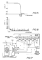
- Fig. 5 is a diagram showing actually measured amplitude-frequency characteristics of such FIR low-pass filter.
- Fig. 6 shows actually measured spectrum of a sinusoidal wave signal passing through the FIR low-pass filter of the characteristics of Fig. 5. As will be apparent from this figure, noise components other than the fundamental wave are certainly attenuated to below - 80 dB.
- respective orders (from 0-th order to m - 1-th order) of filter coefficients of orders m correspond to continuous values of the address signal with resolution of the decimal section FAD and a predetermined reference order (e.g., order k at the center) corresponds to position of the decimal section FAD of the current address signal (i.e., position of the current phase CAD).
- Orders of n which are spaced from the reference order by amounts corresponding to distances of the respective integer sections IAD of n sample points with respect to the decimal section FAD of the current address signal are skippingly determined and n filter coefficients corresponding to the n orders determined in accordance with the decimal section of the current address signal are supplied by the filter coefficient supply means 3.
- IAD - 2 k - FAD + 2d
- orders of n are determined in accordance with the decimal section FAD of the current address signal by means of the above described table or an operation circuit implementing the above formula and coefficient data corresponding to the n orders thus determined are provided.
- the filter coefficient supply means 3 comprises filter coefficient generation means 3a generating filter coefficients of orders m (from 0-th to m - 1-th) and selection means 3b selecting n filter coefficients among these filter coefficients of orders m in accordance with value of the decimal section FAD of the address signal.
- Selection means 3b comprises for example the above described table and determines by this table orders k - FAD - 2d, k - FAD - d, k - FAD, k - FAD + d, k - FAD + 2d and k - FAD + 3d corresponding to the respective integer sections IAD - 2, IAD - 1, IAD, IAD + 1, IAD + 2 and IAD + 3 of n sample points and thereby selects and outputs filter coefficients h (i - 2d), h(i - d), h(i), h(i + d), h(i + 2d) and h(i + 3d) corresponding to the skippingly determined orders.
- the digital filter operation means 4 consists of an FIR filter and comprises delay means 4a which delays tone waveshape data generated by the tone waveshape data generation means 2 in response to the integer section IAD of the address signal by clock pulse (fs) of the sampling frequency fs.
- This delay means 4a supplies sampled data X(Ii - 2), X(Ii - 1), X(Ii), X(Ii + 1), X(Ii + 2) and X(Ii + 3) corresponding to the respective integer sections IAD - 2, IAD - 1, IAD, IAD + 1, IAD + 2 and IAD 3.
- the filter coefficients h(i - 2d) - h(i + 3d) supplied by the selection means 3b may be suitably delayed in accordance with the delay of sampled data X(Ii) and thereafter supplied to the multipliers 4b1 - 4b6.
- the digital filter is constructed as an FIR filter of low-pass filter characteristics for removing aliasing noise as in the previously described embodiment.
- a keyboard 10 comprises keys for designating tone pitches of tones to be generated. Keys depressed in the keyboard 10 are detected by a key assigner 11 and generation of tones corresponding to the depressed keys are any of tone generation channels. The number of the tone generation channels is for example 8 and the respective channels are established by using common tone generation means on a time shared basis.
- the key assigner 11 produces a key code KC of keys assigned to the respective channels, a key-on signal KON and a key-on pulse KONP on a time shared basis in accordance with channel timing.
- An address signal generation circuit 12 receives the key code KC and the key-on pulse KONP from the key assigner 11 and thereupon generates an address signal which changes at a rate corresponding to the tone pitches of the keys assigned to the respective channels on a time shared basis in accordance with the channel timing.
- This address signal consists, as described above, of the integer section IAD and the decimal section FAD.
- the integer section IAD consists for example of 18-bit data and designates continuous sample points of a tone waveshape consisting of plural periods prepared in a tone waveshape memory 13.
- the decimal section FAD is 6-bit data as described above.
- the tone waveshape memory 13 stores data of plural period waveshape of an attack portion and data of plural period waveshape of a sustain portion and the address signal generation circuit 12 generates the address signal, reading out the data of the plural period waveshape of the attack portion once using the key-on pulse KONP as a trigger and thereafter reading out repeatedly the data of the plural period waveshape of the sustain portion.
- the manner of generating the address signal in the address signal generation circuit 1 any method including one in which frequency number is repeatedly operated, a variable frequency dividing method and a method counting a note clock may be employed.
- a touch detection device 14 is provided for detecting touch of the depressed key.
- the tone waveshape memory 13 stores, for example, sampled data of plural period waveshape as described above.
- the tone waveshape memory 13 stores plural sets of such waveshape sampled data in a tone color selection circuit 15 in correspondence to selectable tone colors.
- the tone waveshape memory 13 may further store plural sets of waveshape sampled data for key scaling control of a tone color in accordance with tone pitch or control of a tone color in accordance with a key touch.
- tone color selection code TC, key code KC and touch data TD are applied to the tone waveshape memory 13 and a waveshape to be read out is selected in accordance with these data and read out in response to the integer section IAD of the address signal.
- the data of the integer section IAD of the address signal generated by the address signal generation circuit 12 is applied to phase address input of the tone waveshape memory 13, not directly but through operators (subtractor 16 and adder 17). These operators 16 and 17 perform a function which is equivalent to sampled data delay means in the digital filter (one corresponding to 4a in Fig. 7).
- Fig. 9 specifically shows an operation timing for performing this operation.
- Time division timings CH1 - CH8 of 8 channels are formed by dividing one period of this pulse by 8 and filter operation time slots for 6 orders are formed by dividing time division time slot of each channel by 6.
- One period of the filter operation time slot is one period of master clock pulse MC.
- SLCTR slot count data which distinguishes filter operation time slots 0, 1, 2, 3, 4 and 5 in one channel time slot is obtained.
- SMC designates a filter operation cycle pulse whose one period synchronizes with one channel time slot. If the calculation cycle pulse CAC is 50 kHz, the filter operation cycle pulse SMC is 400 kHz and the master clock pulse MC is 2.4 MHz.
- These pulses and count data are generated by a master clock generator 22 and a timing signal generation circuit 23.
- the subtractor 16 subtracts 2 from IAD for obtaining a value of the integer section IAD - 2 which is 2 sample points before the integer section IAD of the current address signal.
- the data IAD -2 thus obtained is applied to the adder 17 in which the slot count data SLCTR is added. Since this slot count data SLCTR changes 0, 1, 2, 3, 4, 5 within one channel time slot as shown in Fig 9, address data of the respective integer sections IAD - 2, IAD -1, IAd, IAD + 1, IAD 2 and IAD + 3 of 6 sample points are generated from the adder 17 on a time shared basis in correspondence to 6 filter operation time slots 0, 1, 2, 3, 4 and 5 within one channel time slot.
- sampled data corresponding to the respective integer sections IAD - 2, IAD - 1, IAD, IAD + 1, IAD + 2 and IAd + 3 of these 6 sample points are read out from the memory 13 on a time shared basis.
- the sampled data read out from the memory 13 are applied to a multiplier 18 provided for filter coefficient multiplication.
- the filter coefficients are supplied from a filter coefficient supply circuit 24 in a manner to be described later in response to the decimal section FAD of the address signal.
- the output of the multiplier 18 is applied to an accumulator 19 in which sum of convolution is obtained.
- This accumulator 19 performs accumulation at a timing of the master clock pulse MC (i.e., at each step of the slot count data SLCTR) and is cleared at a timing of the filter operation cycle pulse SMC.
- the convolution sum obtained by the current operation is latched by a latch circuit 20.
- the portion including the subtractor 16, adder 17, multiplier 18, accumulator 19 and latch circuit 20 corresponds to a digital filter operation circuit 21 of FIR type.
- the filter coefficient memories 25 and 26 of 2 channels are of the entirely same structure and are provided for parallelly producing adjacent 2 filter coefficients for interpolation in the interpolation circuit 28.
- the impulse response of filter coefficients stored in these filter coefficient memories 25 and 26 is, for example, as shown in the Fig. 4c described above.
- the selection means 27 comprises a subtractor 29, a multiplier 30 and adder 31 for performing this determination by arithmetic operation.
- the output of the adder 31 is applied to the filter coefficient memory 25 and also is applied to the filter coefficient memory 26 after 1 is added thereto by an adder 32.
- 2 filter coefficient data of adjacent orders are read out from the filter coefficient memories 25 and 26.
- These 2 filter coefficient data are applied to the interpolation circuit 28 and are subject to interpolation with interpolation characteristics (e.g., linear interpolation characteristics) of 4 steps in response to rightmost 2-bit data of the decimal section FAD of the address signal.
- interpolation characteristics e.g., linear interpolation characteristics
- the filter operation output signal provided from the latch circuit 20 is applied to a multiplier 33 in which it is multiplied with an amplitude envelope signal supplied from an envelope generator 34.
- the envelope generator 34 generates, in response to the key-on signal KON, an envelope shape signal controlled in response to the key code KC, tone color selection code TC and touch data TD.
- the output of the multiplier 33 is applied to an accumulator 35 in which sum of sampled data of all channels is obtained.
- This accumulator 35 performs accumulation at a timing of the filter operation cycle pulse SMC (i.e., at each channel timing) and is cleared at a timing of the calculation cycle pulse CAC. Immediately before clearing the accumulated value, sum of sampled data of all channels is latched by a latch circuit 36.
- the output signal of the latch circuit 36 is converted to an analog signal by a digital-to-analog converter 37 and thereafter is supplied to a sound system 38.
- the output signal of the latch circuit 36 is also applied to a digital effect circuit 39 provided for imparting musical effects such as reverberation, echo and other musical effects and the signal imparted with the musical effects is converted to an analog signal by a digital-to-analog converter 37 and supplied to the sound system 38.
- tone waveshape sampled data of the sampling frequency fs 50 kHz shown in Fig.
- convolution sum of the sampled data of Fig. 10a and the impulse response of Fig. 10b is obtained by causing the phase CAD of the current address signal to correspond to a predetermined reference order k (e.g., intermediate 47-th order).
- Fig. 10c The spectrum envelope of the waveshape shown in Fig. 10a is shown in Fig. 10c.
- unnecessary harmonic components are conveniently attenuated.
- unnecessary aliasing component is sufficiently attenuated.
- Fig. 11 the same component parts as in Fig. 8 are designated by the same reference characters. Modified portions are subtractor 160, master clock generator 220, timing signal generation circuit 230 and filter coefficient memories 250 and 260 corresponding to subtractor 16, master clock generator 22, timing singal generation circuit 23 in Fig. 8. As described above, in this embodiment, addition of products by 7 times is carried out in the filter operation of one sample point so that 7 filter operation time slots are necessary in one channel time slot and the operation timing is changed as shown in Fig. 12.
- the time division time slot of each channel however is divided by 7 into 7 filter operation time slots.
- the slot count data SLCTR in this embodiment is modified to distinguish 7 filter operation time slots 0, 1, 2, 3, 4, 5 and 6 within one channel time slot.
- the frequency of the master clock pulse MC is modified to 2.8 MHz.
- structures of the master clock generator 220 and the timing signal generation circuit 230 are modified.
- data provided from the adder 31 of the selection means 27 in correspondence to values 0 - 6 of the slot count data SLCTR does not represent orders themselves but addresses of the filter coefficient memories 250 and 260 as shown in Table 3.
- Values of coefficient memory address data provided from the adder 31 of the selection means 27 in correspondence to values 0 - 6 of the slot count data SLCTR in response to the decimal section FAD of the address signal are shown in the following Table 4. This table shows also corresponding integer sections IAD - 3, IAD - 2, IAD - 1, IAD, IAD + 1, IAD + 2 and IAD + 3 of 7 sample points.
- the concept of memory reading in this embodiment is, as in the previously described embodiment, to cause coefficient data stored at address 63 corresponding to an intermediate order (47-th order) used as the reference to correspond to the decimal section FAD of the current address signal, determine skippingly 7 coefficient memory addresses spaced from the reference address 63 by amounts corresponding to distances of the respective integer sections IAD - 3, IAD - 2, IAD - 1, IAD, IAD + 1, IAD + 2 and IAD + 3 of 7 sample points from the decimal section FAD of this current address signal, and read out 7 sets of filter coefficient group value data from the 7 coefficient memory addresses thus determined. Further, as in the previously described embodiment, filter coefficient group value data of adjacent addresses are parallelly read out from the two memories 250 and 260 and interpolation is performed between the two data.
- the coefficient memory address is 9 when SLCTR is 0 and sum data of filter coefficients of 0-th to 8-th orders is read out from the filter coefficient memory 250.
- SLCTR the address is 25 and sum data of filter coefficients of 9-th to 24-th orders is read out.
- SLCTR the address is 41 and sum data of filter coefficients of 25-th to 40-th orders is read out.
- SLCTR 3
- SLCTR the address is 57 and sum data of filter coefficients of 41st to 56-th orders is read out.
- SLCTR is 4 the address is 73 and sum data of filter coefficients of 57-th to 72-nd orders is read out.
- the operators controlling address of the tone waveshape memory 13 is provided in the digital filter operation circuit 21 as means for delaying sampled data instead of actually providing a delay circuit.
- a delay circuit may actually be provided as shown in Fig. 7.
- the tone waveshape memory 13 storing plural period waveshape is provided.
- the tone waveshape sampled data generation means is not limited to this but any other system such as a tone waveshape memory storing merely a waveshape of one period, a system for generating tone waveshape sampled data by frequency modulation operation, a system for generating tone waveshape sampled data by amplitude modulation operation and a system for generating tone waveshape sampled data by data converting address data may be employed.
- the tone generation and filter operation in the respective channels are carried out on a time shared basis. These processings may however be carried out by parallel processings.
- the invention is applicable to not only a polyphonic tone generation system but also a monophonic tone generation system.
- these data may be applied to the address signal generation circuit 12 instead of the tone waveshape memory 13 and the address signal generation circuit 12 may be modified so that it can select these data by leftmost bits of the address signal.
- filter coefficients for all orders need not be stored in the memory but, instead, half of the filter coefficients may be stored and one filter coefficient may be commonly used for also a filter coefficient of the same value located at the symmemtrical position at a different order.
- the filter coefficient memories 25 and 26 or 250 and 260 may be combined into one memory and 2 adjacent coefficient data for the interpolation may be read out on a time shared basis. In that case, the frequency of the master clock pulse MC is doubled and 2 time division time slots for the interpolation are formed within one filter operation time slot.
- the filter coefficients read out from the memory are interpolated in 4 steps.
- the number of interpolation steps is not limited to this.
- the interpolation itself may even be omitted.
- the type of filter operation is not limited to the above described FIR type but IIR (infinite impulse response) type or other type of filter may be employed.
- the digital filter used in the present invention is applicable not only to the removal of aliasing noise as in the above described embodiments but also to other purposes including tone color control.
- an arrangement should be made so that filter characteristics may be selected in accordance with the tone color selection code TC, key code KC and toch data TD.
- plural filter coefficient data corresponding to plural filter characteristics are respectively stored in a filter coefficient memory, a set of filter coefficient data which can realize a desired tone color is selected in accordance with the tone color selction code TC, key code KC and touch data TD and this set of filter coefficients is read out in response to the decimal section of the address signal.
- a reduced number of filter coefficient data may be prestored in the memory and filter coefficient data may be densely produced by interpolating these filter coefficient data in response to the key code KC and touch data TD.
- the tone signal generation device may be provided in plural systems and tone signals generated in these channels may be synthesized by interpolation in response to the key code KC and touch data TD.
- tone waveshape sampled data is generated by the pitch non-synchronization system in which the sampling frequency is constant regardless of pitch of a tone signal.
- the invention is applicable also to a case in which tone waveshape sampled data is generated by the pitch synchronization system in which the sampling frequency synchronizes with pitch of a tone signal.
- the address signal may be controlled in such a manner that the data will be read out intermittently in a high frquency region, e.g., every other times or once in 4 times.
- tone waveshape sampled data is generated in accordance with the integer section of the address signal which changes in accordance with tone pitch of a tone to be generated, n coefficient data among coefficient data corresponding to filter coefficients of m orders (n ⁇ m) are selected in response to the decimal section of the address signal and filter operations of m orders are performed with respect to tone waveshape data of n sample points by using tone waveshape data of n sample points generated in correspondence to the integer section of the address signal.
- the invention therefore produces the following advantageous results: (1)
- the resolution of tone waveshape sampled data actually prepared in the tone waveshape data generation means may be a relatively coarse one corresponding to the integer section of the address signal.
- the circuit construction therefore can be simplified.
- the filter operation may be made actually with respect to limited number of orders corresponding to tone waveshape data of n sample points which n is smaller than m.
- the circuit construction of the digital filter circuit can also be simplified.
- the filter operation substantially becomes equivalent to an accurate filter operation of m orders made with respect to tone waveshape sampled data of high accuracy having resolution of the decimal section of the address signal. This contributes to various advantages brought about by a filter operation performed with respect to tone waveshape sampled data of high resolution including the advantage that removal of an unnecessary noise component is ensured with resulting production of a tone signal of high quality.
Landscapes
- Engineering & Computer Science (AREA)
- Physics & Mathematics (AREA)
- Acoustics & Sound (AREA)
- Multimedia (AREA)
- General Engineering & Computer Science (AREA)
- Analogue/Digital Conversion (AREA)
- Electrophonic Musical Instruments (AREA)
Claims (9)
- Tonsignalerzeugungsvorrichtung mit:
einer Adreßsignalerzeugungseinrichtung (1;12) zum Erzeugen eines Adreßsignals mit einem Ganzzahlbereich (IAD) und einem Dezimalbereich (FAD), wobei der Wert des Adreßsignals sich mit einer der Tonhöhe eines zu erzeugenden Tones entsprechenden Rate verändert;
einer auf den Ganzzahlbereich reagierenden Tonwellenformdatenerzeugungseinrichtung (2;13) zum Erzeugen einer Tonwellenform in der Form von Abtastwerten;
gekennzeichnet durch:
eine Filterkoeffizienten-Liefereinrichtung (3;24), die imstande ist, n Filterkoeffizienten aus einer Gruppe von m Filterkoeffizienten als Reaktion auf den Dezimalbereich (FAD) zu liefern, wobei n und m Ganzzahlige sind und n<m ist; und
eine Digitalfilteroperationseinrichtung (4;21) mit einer m-Ordnungs-Struktur zum digitalen Filtern der Tonwellenform entsprechend der n Filterkoeffizienten. - Tonsignalerzeugungsvorrichtung nach Anspruch 1, bei der die Filterkoeffizienten-Liefereinrichtung (3;24) eine Filterkoeffizientenerzeugungseinrichtung (3a;25,26) zum Erzeugen der m Filterkoeffizienten sowie eine Auswähleinrichtung (3b;27) zum Auswählen der n Filterkoeffizienten als Reaktion auf den Dezimalbereich (FAD) des Adreßsignals aufweist.
- Tonsignalerzeugungsvorrichtung nach Anspruch 1, bei der m Filterkoeffizienten jeweils aufeinanderfolgenden Werten des Adreßsignals entsprechen und bei der die Filterkoeffizienten-Liefereinrichtung (3;24) eine vorbestimmte Referenzordnung (k) auswählt, die dem Dezimalbereich (FAD) einer aktuellen Version des Adreßsignals (CAD) entspricht, wobei die Filterkoeffizienten-Liefereinrichtung (24) n Ordnungen bestimmt, die sich von der Referenzordnung (k) durch Werte unterscheiden, die Intervallen zwischen jeweiligen Ganzzahlbereichen (IAD) von n Abtastpunkten und dem Dezimalbereich des aktuellen Adreßsignals (CAD) entsprechen, und die Filterkoeffizienten-Liefereinrichtung n Filterkoeffizienten liefert, die den so als Reaktion auf den Dezimalbereich (FAD) des aktuellen Adreßsignals bestimmten n Ordnungen entsprechen.
- Tonsignalerzeugungsvorrichtung nach Anspruch 1, bei der n mit einer Relation

- Tonsignalerzeugungsvorrichtung nach Anspruch 1, bei der die den Filterkoeffizientendaten der m Ordnungen entsprechenden Koeffizientendaten ein Filterkoeffizientgruppenwert sind, der einer Gesamtheit eines oder mehrerer Filterkoeffizienten der m Ordnungen entspricht; und
die Filterkoeffizienten-Liefereinrichtung (3;24) die Filterkoeffizientgruppenwerte von n Gruppen (wobei n<m ist) als Reaktion auf den Dezimalbereich des Adreßsignals auswählt und liefert. - Tonsignalerzeugungsvorrichtung nach Anspruch 5, bei der die Filterkoeffizienten-Liefereinrichtung (24) eine Filterkoeffizientenerzeugungseinrichtung (250,260) zum Erzeugen der Filterkoeffizientgruppenwerte, die mehreren Gruppen entsprechen, sowie eine Auswahleinrichtung (27) zum Auswählen von Filterkoeffizientwerten von n Gruppen aus den Filterkoeffizientgruppenwerten, die diesen mehreren Gruppen auf den Wert des Dezimalbereichs (FAD) des Adreßsignals hin entsprechen, aufweist.
- Tonsignalerzeugungsvorrichtung nach Anspruch 5, bei der jeweilige Ordnungen der Filterkoeffizienten von m Ordnungen stetigen Werten des Adreßsignals mit Auflösung des Dezimalbereichs (FAD) entsprechen und bei der die FilterkoeffizientenLiefereinrichtung (24) eine vorbestimmte Referenzordnung (k) auswählt, die dem Dezimalbereich des Adreßsignals entspricht, wobei die Filterkoeffizienten-Liefereinrichtung (24) n Ordnungen bestimmt, die sich von der Referenzordnung (k) durch Werte unterscheiden, die Intervallen zwischen jeweiligen Ganzzahlbereichen (IAD) von n Abtastpunkten und dem Dezimalbereich (FAD) des Adreßsignals entsprechen, wobei Filterkoeffizientgruppenwerte von n Gruppen durch Summieren von Filterkoeffizienten der Ordnungen erhalten werden, die zwischen den jeweiligen Abtastpunkten bei jeder Ordnung vorhanden sind, entsprechend jedem so bestimmten Abtastpunkt, und die Filterkoeffizienten-Liefereinrichtung (24) die Filterkoeffizientgruppenwerte von n Gruppen liefert, die so als Reaktion auf den Dezimalbereich (FAD) des aktuellen Adreßsignals bestimmt werden.
- Tonsignalerzeugungsvorrichtung mit:
einer Adreßsignalerzeugungseinrichtung (1;12) zum Erzeugen eines Adreßsignals mit einem Ganzzahlbereich (IAD) und einem Dezimalbereich (FAD), das sich mit einer der Tonhöhe des zu erzeugenden Tones entsprechenden Rate verändert;
einer Tonwellenformerzeugungseinrichtung (2;13) zum Erzeugen von Tonwellenformabtastdaten als Reaktion auf den Ganzzahlbereich (IAD) des Adreßsignals;
gekennzeichnet durch:
eine auf den Dezimalbereich des Adreßsignals reagierende Filterkoeffizienten-Liefereinrichtung (3;24) zum Auswählen und Liefern von Koeffizientendaten entsprechend nicht-stetiger n Ordnungen, aus Koeffizientendaten, die den Filterkoeffizienten der m Ordnungen entsprechen, wobei n und m Ganzzahlige sind und n<m ist; und
einer Digitalfilteroperationseinrichtung (4;21) zum Durchführen einer Digitalfilteroperation durch Verwenden der Koeffizientendaten, die den nichtstetigen n Ordnungen, die von der Filterkoeffizienten-Liefereinrichtung geliefert werden, sowie den Tonwellenformabtastdaten, die von der Tonwellenformdatenerzeugungseinrichtung (2;13) erzeugt werden, entsprechen. - Tonsignalerzeugungsvorrichtung mit:
einer Adreßsignalerzeugungseinrichtung (1;12) zum Erzeugen eines Adreßsignals, das einen Ganzzahlbereich (IAD) und einen Dezimalbereich (FAD) aufweist und sich mit einer Rate verändert, die der Tonhöhe des zu erzeugenden Tones entspricht;
einer Tonwellenformdatenerzeugungseinrichtung (2;13) zum Erzeugen von Tonwellenformabtastdaten als Reaktion auf den Ganzzahlbereich (IAD) des Adreßsignals;
gekennzeichnet durch:
eine Filterkoeffizienten-Liefereinrichtung (3;24), die imstande ist, Filterkoeffizientgruppenwerte, von denen ein jeder einer Gesamtheit aus einem oder mehreren Filterkoeffizienten aus Filterkoeffizienten von m Ordnungen entspricht, zu liefern sowie die Filterkoeffizientgruppenwerte aus n Gruppen auszuwählen und zu liefern, wobei n und m Ganzzahlige sind und n<m ist, in Reaktion auf den Dezimalbereich des Adreßsignals; und
eine Digitalfilteroperationseinrichtung (4;21) zum Durchführen von Filteroperationen von m Ordnungen in bezug auf die Tonwellenformdaten von n Abtastpunkten unter Verwendung von Filterkoeffizientwerten von n Gruppen, die von der Filterkoeffizienten-Liefereinrichtung (3;24) geliefert werden, sowie von von der Tonwellenformdatenerzeugungseinrichtung (2;13) erzeugten Tonwellenformdaten von n Abtastpunkten.
Applications Claiming Priority (2)
| Application Number | Priority Date | Filing Date | Title |
|---|---|---|---|
| JP311285/86 | 1986-12-30 | ||
| JP61311285A JPH0754432B2 (ja) | 1986-12-30 | 1986-12-30 | 楽音信号発生装置 |
Publications (3)
| Publication Number | Publication Date |
|---|---|
| EP0273447A2 EP0273447A2 (de) | 1988-07-06 |
| EP0273447A3 EP0273447A3 (en) | 1990-03-07 |
| EP0273447B1 true EP0273447B1 (de) | 1993-04-28 |
Family
ID=18015294
Family Applications (1)
| Application Number | Title | Priority Date | Filing Date |
|---|---|---|---|
| EP19870119324 Expired - Lifetime EP0273447B1 (de) | 1986-12-30 | 1987-12-29 | Tonsignalerzeugungsvorrichtung mit einem digitalen Filter |
Country Status (5)
| Country | Link |
|---|---|
| EP (1) | EP0273447B1 (de) |
| JP (1) | JPH0754432B2 (de) |
| DE (1) | DE3785654T2 (de) |
| HK (1) | HK168695A (de) |
| SG (1) | SG6495G (de) |
Families Citing this family (13)
| Publication number | Priority date | Publication date | Assignee | Title |
|---|---|---|---|---|
| JPH0285895A (ja) * | 1988-09-22 | 1990-03-27 | Casio Comput Co Ltd | 電子楽器の楽音波形合成装置 |
| DE3943797B4 (de) * | 1988-11-19 | 2004-11-18 | Sony Computer Entertainment Inc. | Vorrichtung zum Verarbeiten von Quelltondaten |
| DE3938311C2 (de) * | 1988-11-19 | 2002-03-28 | Sony Computer Entertainment Inc | Vorrichtung zum Erzeugen von Quelltondaten |
| US5086475A (en) * | 1988-11-19 | 1992-02-04 | Sony Corporation | Apparatus for generating, recording or reproducing sound source data |
| DE69018687T2 (de) * | 1989-04-21 | 1996-01-25 | Yamaha Corp | Musiksynthesizer. |
| US5194681A (en) * | 1989-09-22 | 1993-03-16 | Yamaha Corporation | Musical tone generating apparatus |
| JP2576647B2 (ja) * | 1989-11-30 | 1997-01-29 | ヤマハ株式会社 | 波形発生装置 |
| JPH03221997A (ja) * | 1990-01-29 | 1991-09-30 | Kawai Musical Instr Mfg Co Ltd | 電子楽器 |
| JP2623942B2 (ja) * | 1990-09-05 | 1997-06-25 | ヤマハ株式会社 | 楽音信号発生装置 |
| JP2722907B2 (ja) * | 1991-12-13 | 1998-03-09 | ヤマハ株式会社 | 波形発生装置 |
| US5416264A (en) * | 1992-07-27 | 1995-05-16 | Yamaha Corporation | Waveform-forming device having memory storing non-compressed/compressed waveform samples |
| FR2973186A1 (fr) | 2011-03-22 | 2012-09-28 | Sagemcom Broadband Sas | Procede et dispositif de configuration sur la base de regles de gestion |
| JP6079982B2 (ja) * | 2012-03-05 | 2017-02-15 | カシオ計算機株式会社 | 楽音発生装置、楽音発生方法およびプログラム |
Family Cites Families (15)
| Publication number | Priority date | Publication date | Assignee | Title |
|---|---|---|---|---|
| JPS5851307B2 (ja) * | 1974-07-11 | 1983-11-15 | ヤマハ株式会社 | ハケイハツセイソウチ |
| US4036096A (en) * | 1974-07-11 | 1977-07-19 | Nippon Gakki Seizo Kabushiki Kaisha | Musical tone waveshape generator |
| US4020332A (en) * | 1975-09-24 | 1977-04-26 | Bell Telephone Laboratories, Incorporated | Interpolation-decimation circuit for increasing or decreasing digital sampling frequency |
| JPS5917838B2 (ja) * | 1977-11-01 | 1984-04-24 | ヤマハ株式会社 | 電子楽器の波形発生装置 |
| US4245541A (en) * | 1979-06-01 | 1981-01-20 | Kawai Musical Instrument Mfg. Co., Ltd. | Apparatus for reducing noise in digital to analog conversion |
| US4256003A (en) * | 1979-07-19 | 1981-03-17 | Kawai Musical Instrument Mfg. Co., Ltd. | Note frequency generator for an electronic musical instrument |
| JPS572115A (en) * | 1980-06-05 | 1982-01-07 | Casio Comput Co Ltd | Digital filter device |
| JPS572116A (en) * | 1980-06-05 | 1982-01-07 | Casio Comput Co Ltd | Digital filter device |
| JPS572114A (en) * | 1980-06-05 | 1982-01-07 | Casio Comput Co Ltd | Digital filter device |
| JPS5898793A (ja) * | 1981-12-08 | 1983-06-11 | パイオニア株式会社 | 音声合成装置 |
| JPS5952911A (ja) * | 1982-09-20 | 1984-03-27 | Nec Corp | トランスバ−サル・フイルタ |
| JPS61286899A (ja) * | 1985-06-14 | 1986-12-17 | 赤井電機株式会社 | 電子楽器 |
| JPH0732343B2 (ja) * | 1985-04-17 | 1995-04-10 | 日本電気株式会社 | 非同期標本化周波数変換方式 |
| JPH0631989B2 (ja) * | 1985-11-14 | 1994-04-27 | ロ−ランド株式会社 | 電子楽器の波形発生装置 |
| JPH0631989A (ja) * | 1992-07-16 | 1994-02-08 | Olympus Optical Co Ltd | ページプリンタの印字制御方法 |
-
1986
- 1986-12-30 JP JP61311285A patent/JPH0754432B2/ja not_active Expired - Lifetime
-
1987
- 1987-12-29 DE DE19873785654 patent/DE3785654T2/de not_active Expired - Lifetime
- 1987-12-29 EP EP19870119324 patent/EP0273447B1/de not_active Expired - Lifetime
-
1995
- 1995-01-16 SG SG6495A patent/SG6495G/en unknown
- 1995-11-02 HK HK168695A patent/HK168695A/en not_active IP Right Cessation
Also Published As
| Publication number | Publication date |
|---|---|
| EP0273447A3 (en) | 1990-03-07 |
| JPS63168695A (ja) | 1988-07-12 |
| SG6495G (en) | 1995-06-16 |
| DE3785654D1 (de) | 1993-06-03 |
| HK168695A (en) | 1995-11-10 |
| DE3785654T2 (de) | 1993-10-07 |
| JPH0754432B2 (ja) | 1995-06-07 |
| EP0273447A2 (de) | 1988-07-06 |
Similar Documents
| Publication | Publication Date | Title |
|---|---|---|
| EP0178840B1 (de) | Tonsignalbehandlungsvorrichtung | |
| EP0273447B1 (de) | Tonsignalerzeugungsvorrichtung mit einem digitalen Filter | |
| KR0150223B1 (ko) | 악음신호발생장치 | |
| EP0199192B1 (de) | Tonsignalerzeugungsvorrichtung | |
| EP0187211B1 (de) | Tonsignalerzeugungsvorrichtung | |
| US4829463A (en) | Programmed time-changing coefficient digital filter | |
| EP2063413B1 (de) | Vorrichtung zum Hinzufügen eines Widerhalleffekts | |
| EP0229926B1 (de) | Tonsignalsbehandlungsvorrichtung | |
| US5250748A (en) | Tone signal generation device employing a digital filter | |
| JPH0795235B2 (ja) | 電子楽器 | |
| JP2833403B2 (ja) | 電子楽器の音源装置 | |
| GB2087124A (en) | Method and apparatus for generating musical tone signals | |
| JP2765306B2 (ja) | 音源装置 | |
| JPS6410837B2 (de) | ||
| JPS6239744B2 (de) | ||
| JP2708037B2 (ja) | 楽音信号発生装置 | |
| JP3435702B2 (ja) | 楽音発生装置 | |
| JPS6091227A (ja) | 音響解析装置の合成装置 | |
| JPH0369119B2 (de) | ||
| JP2671648B2 (ja) | ディジタルデータの補間装置 | |
| JP2897680B2 (ja) | 楽音信号発生装置 | |
| JPH064077A (ja) | ディジタルフィルタ | |
| JPH0968985A (ja) | 楽音合成装置 | |
| JPH05119780A (ja) | 音源装置 | |
| JPH0484784A (ja) | 模擬船舶航行雑音発生装置 |
Legal Events
| Date | Code | Title | Description |
|---|---|---|---|
| PUAI | Public reference made under article 153(3) epc to a published international application that has entered the european phase |
Free format text: ORIGINAL CODE: 0009012 |
|
| AK | Designated contracting states |
Kind code of ref document: A2 Designated state(s): DE GB |
|
| 17P | Request for examination filed |
Effective date: 19890428 |
|
| PUAL | Search report despatched |
Free format text: ORIGINAL CODE: 0009013 |
|
| AK | Designated contracting states |
Kind code of ref document: A3 Designated state(s): DE GB |
|
| 17Q | First examination report despatched |
Effective date: 19920127 |
|
| GRAA | (expected) grant |
Free format text: ORIGINAL CODE: 0009210 |
|
| AK | Designated contracting states |
Kind code of ref document: B1 Designated state(s): DE GB |
|
| REF | Corresponds to: |
Ref document number: 3785654 Country of ref document: DE Date of ref document: 19930603 |
|
| PLBE | No opposition filed within time limit |
Free format text: ORIGINAL CODE: 0009261 |
|
| STAA | Information on the status of an ep patent application or granted ep patent |
Free format text: STATUS: NO OPPOSITION FILED WITHIN TIME LIMIT |
|
| 26N | No opposition filed | ||
| REG | Reference to a national code |
Ref country code: GB Ref legal event code: IF02 |
|
| PGFP | Annual fee paid to national office [announced via postgrant information from national office to epo] |
Ref country code: DE Payment date: 20061221 Year of fee payment: 20 |
|
| PGFP | Annual fee paid to national office [announced via postgrant information from national office to epo] |
Ref country code: GB Payment date: 20061227 Year of fee payment: 20 |
|
| REG | Reference to a national code |
Ref country code: GB Ref legal event code: PE20 |
|
| PG25 | Lapsed in a contracting state [announced via postgrant information from national office to epo] |
Ref country code: GB Free format text: LAPSE BECAUSE OF EXPIRATION OF PROTECTION Effective date: 20071228 |