EP0272582B1 - Plaques pour contrôle de lumière - Google Patents
Plaques pour contrôle de lumière Download PDFInfo
- Publication number
- EP0272582B1 EP0272582B1 EP87118568A EP87118568A EP0272582B1 EP 0272582 B1 EP0272582 B1 EP 0272582B1 EP 87118568 A EP87118568 A EP 87118568A EP 87118568 A EP87118568 A EP 87118568A EP 0272582 B1 EP0272582 B1 EP 0272582B1
- Authority
- EP
- European Patent Office
- Prior art keywords
- film
- light
- cured
- composition
- sheet
- Prior art date
- Legal status (The legal status is an assumption and is not a legal conclusion. Google has not performed a legal analysis and makes no representation as to the accuracy of the status listed.)
- Expired - Lifetime
Links
Images


Classifications
-
- G—PHYSICS
- G02—OPTICS
- G02B—OPTICAL ELEMENTS, SYSTEMS OR APPARATUS
- G02B26/00—Optical devices or arrangements for the control of light using movable or deformable optical elements
-
- G—PHYSICS
- G02—OPTICS
- G02B—OPTICAL ELEMENTS, SYSTEMS OR APPARATUS
- G02B1/00—Optical elements characterised by the material of which they are made; Optical coatings for optical elements
-
- G—PHYSICS
- G02—OPTICS
- G02B—OPTICAL ELEMENTS, SYSTEMS OR APPARATUS
- G02B1/00—Optical elements characterised by the material of which they are made; Optical coatings for optical elements
- G02B1/04—Optical elements characterised by the material of which they are made; Optical coatings for optical elements made of organic materials, e.g. plastics
-
- G—PHYSICS
- G02—OPTICS
- G02B—OPTICAL ELEMENTS, SYSTEMS OR APPARATUS
- G02B1/00—Optical elements characterised by the material of which they are made; Optical coatings for optical elements
- G02B1/10—Optical coatings produced by application to, or surface treatment of, optical elements
-
- G—PHYSICS
- G02—OPTICS
- G02B—OPTICAL ELEMENTS, SYSTEMS OR APPARATUS
- G02B5/00—Optical elements other than lenses
- G02B5/02—Diffusing elements; Afocal elements
- G02B5/0205—Diffusing elements; Afocal elements characterised by the diffusing properties
- G02B5/0236—Diffusing elements; Afocal elements characterised by the diffusing properties the diffusion taking place within the volume of the element
-
- G—PHYSICS
- G02—OPTICS
- G02B—OPTICAL ELEMENTS, SYSTEMS OR APPARATUS
- G02B5/00—Optical elements other than lenses
- G02B5/02—Diffusing elements; Afocal elements
- G02B5/0205—Diffusing elements; Afocal elements characterised by the diffusing properties
- G02B5/0257—Diffusing elements; Afocal elements characterised by the diffusing properties creating an anisotropic diffusion characteristic, i.e. distributing output differently in two perpendicular axes
-
- G—PHYSICS
- G02—OPTICS
- G02B—OPTICAL ELEMENTS, SYSTEMS OR APPARATUS
- G02B5/00—Optical elements other than lenses
- G02B5/02—Diffusing elements; Afocal elements
- G02B5/0268—Diffusing elements; Afocal elements characterized by the fabrication or manufacturing method
-
- G—PHYSICS
- G02—OPTICS
- G02B—OPTICAL ELEMENTS, SYSTEMS OR APPARATUS
- G02B5/00—Optical elements other than lenses
- G02B5/02—Diffusing elements; Afocal elements
- G02B5/0273—Diffusing elements; Afocal elements characterized by the use
- G02B5/0278—Diffusing elements; Afocal elements characterized by the use used in transmission
-
- G—PHYSICS
- G02—OPTICS
- G02B—OPTICAL ELEMENTS, SYSTEMS OR APPARATUS
- G02B2207/00—Coding scheme for general features or characteristics of optical elements and systems of subclass G02B, but not including elements and systems which would be classified in G02B6/00 and subgroups
- G02B2207/123—Optical louvre elements, e.g. for directional light blocking
-
- Y—GENERAL TAGGING OF NEW TECHNOLOGICAL DEVELOPMENTS; GENERAL TAGGING OF CROSS-SECTIONAL TECHNOLOGIES SPANNING OVER SEVERAL SECTIONS OF THE IPC; TECHNICAL SUBJECTS COVERED BY FORMER USPC CROSS-REFERENCE ART COLLECTIONS [XRACs] AND DIGESTS
- Y10—TECHNICAL SUBJECTS COVERED BY FORMER USPC
- Y10S—TECHNICAL SUBJECTS COVERED BY FORMER USPC CROSS-REFERENCE ART COLLECTIONS [XRACs] AND DIGESTS
- Y10S428/00—Stock material or miscellaneous articles
- Y10S428/919—Camouflaged article
Definitions
- the present invention relates to a process for producing a light control sheet.
- Angle-dependent type light control sheets scatter only incident lights from particular angles and transmit incident lights from all other angles. These sheets are obtained by curing a photocurable material.
- angle-dependent type light control sheets there have conventionally been used those of microlouver types having a laminate structure of transparent sheets and opaque sheets (cf. EP-A-0 066 745 and JP-A-189439/1982) or those having a controlled visual field obtained by drawing a lattice-like pattern of certain thickness and making the pattern opaque.
- These microlouvers however, have a low light transmittance, and gives rise to an interference pattern depending upon the angle of their use.
- conventional oriented films or light-shielding sheets are produced through complex processes, making them costly or their film qualities nonuniform.
- the present invention provides a process as specified in claim 1.
- the process according to the present invention provides a light control sheet capable of scattering an incident light of a particular incident angle range and comprises stages of preparing a film of a composition composed of at least two photopolymerizable components having different refractive indexes and irradiating on said film a light from a particular direction to obtain a cured film.
- light control sheets each capable of scattering a plurality of incident lights each of particular incident angles or an incident light of wide incident angle range, and the following processes for producing said light control sheets:
- the photopolymerizable components used in the present invention are a combination of a plurality of monomers or oligomers which are photopolymerizable under irradiation of such lights as an ultraviolet light.
- the combination has no restriction as long as the monomers or oligomers have different refractive indexes and adequate compatibility with each other, and is determined by considering the chemical and physical properties of the resin formed by curing of the monomers and/or oligomers.
- Preferred as the photopolymerizable monomers or oligomers are those having in the molecule a group such as acryloyl, methacryloyl, vinyl or allyl.
- polyfunctional acrylates such as polyester acrylate, polyol polyacrylate, modified polyol polyacrylate, polyacrylate having an isocyanuric acid skeleton, melamine acrylate, polyacrylate having a hydrantoin skeleton, polybutadiene acrylate, epoxy acrylate, urethane acrylate, bisphenol A disacrylate, 2,2-bis(4-acryloxyethoxy-3,5-dibromophenyl)propane and the like; corresponding methacrylates; monofunctional acrylates such as tetrahydrofuryl acrylate, ethylcarbitol acrylate, dicyclopentenyloxyethyl acrylate, isobornyl acrylate, phenylcarbitol acrylate, nonylphenoxyethyl acrylate, 2-hydroxy-3-phenoxypropyl acetate, ⁇ -hydroxyhexanoyloxyeth
- These compounds can be used as a monomer or as an oligomer thereof.
- the monomers or oligomers to be used as a mixture must have differences in their refractive indexes. The larger the difference in refractive index, the higher is the haze percentage of the cured product. It is preferred that the two or more monomers or oligomers to be used as a mixture have a difference in refractive index of at least 0.01, more preferably at least 0.05. It is also preferred that the two monomers or oligomers having a refractive index difference of at least 0.01 is mixed at a weight ratio of 10 : 90 to 90 : 10.
- the monomers or oligomers used in combination are preferred to have somewhat poor compatibility with each other. When the compatibility is good, the mixture becomes completely uniform and no haze (no cloudiness) is obtained by photocuring. When the compatibility is too poor, phase separation occurs before photocuring and results in a totally haze product.
- the light control sheet can be obtained by irradiating a light on a thin layer of a mixture of the above monomers or oligomers in the presence of a photopolymsrization initiator.
- the light includes a radiation, an ultraviolet light, a visible light, etc., and an ultraviolet light is preferred.
- a photopolymerization initiator used in ordinary photopolymerization can be used without any restriction.
- benzophenone benzil, Michler's ketone, 2-chlorothioxanthone, benzoin ethyl ether, diethoxyacetophenone, benzyl dimethyl ketal, 2-hydroxy-2-methylpropiophenone and 1-hydroxycyclohexyl phenyl ketone as the preferred initiators.
- the light control sheet can be produced by coating on a substrate a composition composed mainly of the above monomers or oligomers and a photopolymerization initiator or filling said composition in a cell formed with two plates transparent to a light to be applied later for the photopolymerization of the composition and arranged apart from each other by a given distance and then irradiating a light to the composition from a particular direction.
- the substrate may be of any material as long as it can transmit a light sufficiently for the initiation of the photopolymerization of the composition. It can be, for example, a plate or retainer plate made of transparent glass, plastic or the like.
- the cell is preferably made of transparent glass, plastic or the like, because at least one side of the cell must transmit a light which is applied for the initiation of the photopolymerization of the composition.
- the light control sheet its deterioration and yellowing caused by an ultraviolet light during actual use, particularly outdoor use, is undesirable.
- additives such as an ultraviolet absorber and the like are usually added to the composition.
- an ultraviolet absorber and the like hinders the curing of the composition when the curing is caused by an ultraviolet light.
- a photopolymerizable composition is held or coated in a film shape on a colorless or colored, ultraviolet-resistant, transparent substrate and then an ultraviolet light is irradiated on the film from the film side opposit to the ultraviolet-resistant transparent substrate to cure the photopolymerizable composition.
- the ultraviolet-resistant transparent substrate there is used a glass plate or a plastic sheet or film of ordinary used ultraviolet-resistant ones. And the quality of the plate, sheet or film is specified by the usages of the obtained light control sheet and the wavelength of the ultraviolet source employed for the curing of the composition.
- an ultraviolet absorber and the like are not added to the composition and, moreover, an ultraviolet-resistant transparent substrate is provided on the opposit side to the composition for not receiving the irradiation of an ultraviolet light. Therefore, a light control sheet can be produced with no hindrance in the curing of the composition.
- the cured film can be prevented from deterioration and yellowing by using the side of the ultraviolet-resistance transparent substrate as a light-receiving side.
- the composition coated on a substrate or filled in a cell must have a certain film thickness.
- the film thickness is at least 20 microns, preferably at least 100 microns, more preferably at least 200 microns.
- the reason is as follows. That is, in the present invention, when the composition is photopolymerized, there is formed, in the vicinity of the surface layer of the cured film, a layer of special structure capable of scattering only an incident light from a particular direction. This layer is considered to comprise minute sheet-shaped pieces having distinguishable refractive indexes and being parallel and directed toward a particular direction. The layer has a thickness of at least 20 microns. Therefore, the film thickness of the coated or filled composition must be at least 20 microns.
- the light source for irradiation used in the present invention is required to be able to emit an ultraviolet light or other light which can contribute to the photopolymerization of the composition.
- the light source must have a linear shape when viewed from the site of the composition film receiving irradiation.
- a mercury lamp, a metal halide lamp or the like is ordinarily preferred in view of the easiness of its handling.
- the light source preferably has such a size, when viewed from the site of the composition film receiving irradiation, the visual angle A of the light source in the major axis direction is at least 8°, preferably at least 12°, and the visual angle B in the minor axis direction is A/4 or smaller, preferably A/10 or smaller.
- a bar-like ultraviolet lamp is one preferred linear light source.
- a bar-like ultraviolet lamp (3 KW) having a length of about 40 cm and a diameter of about 2 cm is kept horizontally 40 cm above a film of 10 cm x 10 cm so that the lamp becomes parallel to the film surface, the visual angle A is about 54° and the visual angle B is about 3°.
- a lamp is a preferred linear light source in the present invention.
- linear light source there can also be used those which appear to be linear when viewed from the site receiving irradiation, including a light source consisting of a large number of point light sources arranged continuously and linearly and a device which scans a light from a laser, etc. using a rotary mirror and a concave mirror (in this case, one irradiation spot is irradiated from a number of different angles).
- the cured film formed shows anisotropy in the major axis direction and the minor axis direction of the ultraviolet light source.
- the film When the film is rotated around an axis having the same direction as the major axis of the light source, the film scatters a light of particular incident angle.
- the incident angle of a light irradiated from a light source on the uncured film for its photopolymerization is defined as a value obtained by substracting from 90° an angle which a fictitious plante including a point on the film receiving irradiation and the major axis of the light source makes against the film surface.
- the above irradiation point when the film has been cured, scatters a light at highest degree when the light hits the point at an incident angle about equal to the above mentioned incident angle of the light source used for the photopolymerization of the uncured film.
- the degree of light scattering and the incident angle range of an incident light at which the light scatters can be varied over a wide range by changing the proportions and/or types of the components of the film composition. Further, when a certain composition is cured, the incident angle range of an incident light at which the light scatters on the resulting cured composition can be varied by changing the incident angle of the ultraviolet light used for the curing of the composition.
- the cured film can be evaluated by obtaining the parallel light transmittance and the haze (the haze percentage). They are obtained by calculation from the total light transmittance and scattered light transmittance of the cured film both measured using an integrating sphere type light transmittance measurement apparatus in accordance with JIS K-6714.
- a cured film obtained by (a) providing a linear light source on a film-shaped composition kept horizontally, in such a state that the light source is about 40 cm above the film at a position about 45° tilted from a plane including the film center and perpendicular to the film surface, and that the lengthwise direction of the light source is parallel to the plane and horizontal, and then (b) irradiating a light on the film from the light source to cure the film.
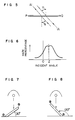
- a microstructure layer 3 is formed in the vicinity of the irradiated surface 2 of the cured film.
- This layer 3 has a thickness d2 of about 10 to 2000 microns and its depth d1 from the irradiated surface 2 is 0 to 500 microns.
- the film thickness d3 is ordinarily 10 to 5000 microns.
- the microstructure layer 3 comprises a large number of minute thin pieces 4 each directed parallel to the lengthwise direction of the linear light source 5.
- Fig. 4 showing a section obtained by cutting the Fig. 2 film at an A-A line, each of the minute pieces 4 is tilted from the above perpendicular plane by an angle Z ⁇ which is smaller than the incident angle Z of an irradiation light from the light source 5.
- This angle Z ⁇ is about equal to the refractable angle at which the light from the light source 5 refracts in the film.
- the pitch d5 of the minute pieces 4 is 0.01 to 50 microns.
- Fig. 6 shows the haze percentages of the cured film toward various lights of different incident angles. The haze percentage is maximum at around the incident angle of Z, giving a mountain-shaped graph.
- the degree of light scattering and the incident angle range of an incident light at which the light scatters can be changed over a wide range by changing the proportions and/or types of the components of the film composition. They can also be changed greatly by changing the irradiation conditions such as the distance of the light source, the size of the light source (e.g. the visual angles A and B) and the output of the light source.
- the anistropy of the cured film becomes insufficient, and when the visual angle A is smaller than 5°, the cured film no longer shows anisotropy and scatters incident lights from all directions.
- the cured film obtained by using a point light source or substantially parallel lights gives light scattering of no directionality.
- the resulting cured film gives a haze percentage graph having a lower height.
- the cured film no longer shows anisotropy.
- the cured film looks transparent when viewed from all directions and gives no light scattering.
- a planar light source provided relatively close to the uncured film, or a diffusion type light source.
- the cured film obtained by thermal polymerization is also transparent.
- a light entering the cured film at an angle close to the inclination angle Z ⁇ of the minute pieces hits the surface of a minute piece 4 at an angle larger than the critical reflection angle determined by the refractive indexes of the minute pieces 4 and the substance 6, and is reflected, and this reflection is repeated on other minute pieces, whereby the lights leaving the cured film become a scattered light as a whole.
- the angle of the light hitting the minute piece becomes smaller than the critical reflection angle and reflection decreases, whereby the lights leaving the cured film are parallel.
- a slight hollow (a small reduction in haze percentage) is observed at the top of the haze percentage graph. This phenomenon occurs presumably because a light having an incident angle Z very close to the inclination angle Z ⁇ of the minute pieces 4 makes no reflection on the minute pieces and moves straight between the two adjacent minute pieces.
- the light source When the light source is a planar or diffusion type, no microstructure is formed and the resulting cured film is transparent and gives no selective light scattering.
- the light source When the light source is a point type, though the microstructure is formed within the cured film which differs from the case of a linear light source and is arranged randomly without any regularity; therefore, it is presumed that all incident lights are reflected within the microstructure and the lights leaving the film are scattered to all directions.
- the light control sheet of the present invention is a plastic sheet. It can also be used by coating on a glass plate, etc.
- the light control sheet or the coated plates are expected to be used in various applications such as window glass, vehicles, displays, mirrors and greenhouses.
- a cured sheet for a light control sheet capable of selectively scattering only a light of particular incident angle.
- a light control sheet capable of selectively scattering a plurality of lights of at least two different incident angles through a process comprising a first step of forming the above-mentioned cured sheet, a second step of preparing on said cured sheet a film of the same or different composition as that used in the first step and irradiating a light from a particular direction different from that used in the first step to obtain a second cured sheet on the first cured sheet and, if desired, a step of repeating the second step.
- the direction of the irradiating light is changed each time, whereby can be produced a light control sheet capable of selectively scattering a plurality of lights of at least three different incident angles.
- a light control sheet capable of scattering lights of at least two different incident angles can be produced simply by using compositions of the same recipe and curing each of them with a light of different incident angle, however, each composition to be repeated may have a different recipe.
- a light control sheet capable of scattering lights having a plurality of different incident angles or a light of wide incident angle range through a process comprising simultaneously irradiating on the film-shaped composition lights from a plurality of linear light sources arranged apart from each other.
- the arrangement of the linear light sources is appropriately made so as to meet the requirements for the light control sheet to be produced in such respects as the direction and angle of light control.
- these light sources When a plurality of linear light sources are arranged parallel to each other, it is preferred that these light sources have a visual angle of at least 10° when viewed from the site of the composition receiving irradiation. If a number of light sources are arranged without being separated, no selective light scattering is obtained as described later.
- the composition film is cured by the light irradiated earlier and the resulting light control sheet can not scatter lights of a plurality of different incident angles or a light of wide incident angle range.
- the previously mentioned minute pieces present in the microstructure layer are presumed to take a form of a mixture of different minute piece groups each having an inclination angle substantially same as the incident angle of a light from each light source.
- the light control sheet can scatter lights having a plurality of different incident angles or a light of wide incident angle range.
- the conventional ultraviolet-cured light control sheets capable of scattering only a light of single direction and narrow incident angle range can be improved to a light control sheet capable of controlling lights of a plurality of different incident angles or a light of wide incident angle range.
- a light control sheet having at least one portion capable of scattering a first light of particular incident angle and at least one other portion capable of scattering a second light of particular incident angle different from that of the first light or totally hazy or totally transparent through a process comprising stages of dividing the surface of a composition film into a plurality of portions by means of, for example, a photomask, irradiating a light from a first linear light source on at least one surface portion, for example, corresponding to the aperture of the photomask to cure the portion, irradiating a light from a different angle from a second light source on at least one other surface portion, for example, covered by the photomask to cure the portion, and if there remain uncured portions, they are cured by photopolymerization or thermal polymerization.
- the irradiation by the second linear light source can be replaced by the irradiation by a point light source, parallel lights or diffused lights, or by heat.
- the irradiations by the first linear light source and the second linear light source or its alternate can be conducted simultaneously or separately. Obtaining a cured portion with an exact shape using heat is generally difficult; therefore, when a cured portion with an exact shape is desired, it is preferred that the irradiation by the first linear light source be made first to obtain such a cured portion and then heat is applied to cure the remaining portion.
- the conventional ultraviolet-cured light control sheet capable of controlling through the entire sheet only a light of single direction and single incident angle could be improved to a light control sheet having a plurality of portions capable of scattering lights of a plurality of different incident angles.
- a light control sheet having a plurality of portions each having a different shape and capable of scattering a light of particular and different incident angle in which said portions may partially overlap with each other through a process comprising stages of providing at one side of a film composition a photomask of first shape and a first linear light source so that the photomask is placed between the film and the first light source, providing at the other side of the film a photomask of second shape and a second linear light source so that the photomask is placed between the film and the second light source, and simultaneously irradiating lights from the first and second light sources through the two photomasks to obtain two cured portions having the first shape and the second shape, respectively.
- the light-controlling function is generated during curing of the film composition. Accordingly, in order for each side of the cured film to have a different light-controlling function, it is desirable that two different photomasks be provided at the both sides of the film and two different lights for photopolymerization of, for example, two different ultraviolet lights be simultaneously irradiated through the photomasks. If only one side is irradiated earlier, the curing of the film proceeds to the other side and it becomes impossible to allow the other side to have a light-controlling function. The portions of the film composition which remain uncured as a result of masking by the two photomasks are polymerized by an ultraviolet light or heat.
- the both sides of the cell must transmit the lights used for photopolymerization. Therefore, the both sides of the cell are preferred to be made of such a material as a transparent glass, a plastic or the like.
- the composition coated on a substrate or filled in a cell must have a film thickness of at least 40 microns, because it is required to form in the film in the vicinity of each surface of the film a microstructure layer comprising minute sheet-shaped pieces of different refractive indexes which are parallel and directed toward a particular direction.
- the conventional ultraviolet-cured light control sheet capable of controlling through the entire sheet only a light of single direction and single incident angle could be improved to a light control sheet having a plurality of portions each having a different shape and capable of scattering a light of particular and different incident angle in which said portions may partially overlap with each other.
- the refractive index of a monomer or oligomer was measured with an Abbe's refractometer at 20°C.
- a polyether-urethane acrylate having the refractive index of 1.481 obtained by the reaction between a polypropylene glycol having an average molecular weight of 2000, toluene diisocyanate and 2-hydroxyethyl acrylate was mixed with 100 parts of N-vinylpyrrolidone having the refractive index of 1.509 and 6 parts of benzyl dimethyl ketal to prepare a resin composition.
- the composition was poured between glass plates having a spacer of 1 mm in thickness between them.
- An ultraviolet light was irradiated for two minutes using a mercury lamp of 120 W provided 30 cm (perpendicular distance) above the glass plates to obtain a cured sheet.
- the sheet was measured for physical properties such as parallel light transmittance and haze percentage. The results are shown in Table 1.
- a cured sheet was obtained from the resin composition of Example 2 in the same manner as in Example 3 except that the ultraviolet light was irradiated at an angle of 45°. The sheet was measured for haze percentage. The angle at the maximum haze percentage was 45° which was smaller by 45° than that in Example 3.
- N-vinylpyrrolidone was mixed with 100 parts of 2,2,3,3-tetrafluoropropyl acrylate and 6 parts of 2-hydroxy-2-methyl-propiophenone to prepare a resin composition.
- the composition was poured between two glass plates having a spacer of 1 mm in thickness between them.
- An ultraviolet light was irradiated for 8 minutes from a mercury lamp (80 W, 40 cm in length) provided 40 cm (perpendicular distance) above the plates, to obtain a cured sheet.
- the sheet was measured for physical properties in the same manner as in Example 1. The results are shown in Table 1.
- Example 1 Thirty parts of the same polyether-urethane acrylate as used in Example 1 was mixed with 70 parts of an equal-amount mixture having a refractive index of 1.590, of tribromophenyl acrylate and a compound (II) represented by the following structural formula (II), and 3 parts of 2-hydroxy-2-methyl-propiophenone to prepare a resin composition.
- the composition was cured in the same manner as in Example 5 to obtain a cured sheet.
- the sheet was measured for physical properties in the same manner as in Example 5. The results are shown in Table 1.
- a polyether-urethane acrylate having a refractive index of 1.481 obtained by the reaction between a polypropylene glycol having an average molecular weight of 2000, toluene diisocyanate and 2-hydroxyethyl acrylate was mixed with 50 parts of a compound (III) having the refractive index of 1.567, represented by the following structural formula (III) and 3 parts of 2-hydroxy-2-methyl-propiophenone to prepare a resin composition.
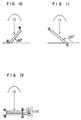
- the composition was poured between two glass plates having a spacer of 200 microns in thickness between them. As shown in Fig.
- an ultraviolet light was irradiated for 3 minutes at a distance of 40 cm and an angle of 30° using a mercury lamp (80 W, 40 cm in length) to obtain a cured sheet. Thereafter, one glass plate was removed, and on the cured sheet was formed a cell comprising a glass plate and the cured sheet having a spacer of 200 microns in thickness between them. The same composition as above was filled in the cell. As shown in Fig. 8, an ultraviolet light was irradiated for 3 minutes at a distance of 40 cm and an angle of 120° using the same mercury lamp to obtain a cured sheet on the previously formed cured sheet. This lamination type sheet was measured for haze percentages at various angles. The resulting angle dependency of haze percentage is shown in Fig. 9.
- a bisphenol A type epoxy acrylate having the refractive index of 1.560 was mixed with 50 parts of 2,2,3,3-tetrafluoropropyl acrylate having the refractive index of 1.363 and 3 parts of 2-hydroxy-2-methyl-propiophenone to prepare a resin composition.
- the composition was poured between two glass plates having a spacer of 1 mm in thickness between them.
- an ultraviolet light was irradiated for 3 minutes at a distance of 40 cm and an angle of 45° using a mercury lamp (80 W, 40 cm in length) to cure a cured sheet (I).
- a cured sheet (II) was obtained at an angle of 135° as shown in Fig. 11.
- the cured sheets (I) and (II) were separated from the glass plates and connected with a spacer of 200 microns in thickness.
- a resin composition (III) was poured between the cured sheets (I) and (II), and an ultraviolet light was irradiated for 3 minutes at an angle of 0° using the same mercury lamp, as shown in Fig. 12, whereby a cured sheet (IV) of lamination type was obtained.
- the haze property of the cured sheet (IV) is shown in Fig. 13.
- Example 9 The same resin composition as in Example 9 was poured between two glass plates having a spacer of 200 microns in thickness between them, and an ultraviolet light was irradiated for 3 minutes at a distance of 25 cm and an angle of 30° using a mercury lamp (80 W, 25 cm in length), as shown in Fig. 14, to obtain a cured sheet.
- a cell comprising one glass plate and the cured sheet having a spacer of 200 microns in thickness between them.
- the same composition was filled in the cell, and a cured sheet was formed in the same manner as above except that the irradiation angle was 50°.
- the similar procedures were conducted at irradiation angles of 70°, 110°, 130° and 150°, whereby a lamination type cured sheet comprising 6 cured sheets was obtained.
- the haze property of the cured sheet is shown in Fig. 15.
- the angle O denotes a direction of perpendicular to the glass plates, passing the center of the glass plates; the minus (-) angles denote left from the perpendicular; and the plus (+) angles denote right from the perpendicular.
- Example 16 above the center of the glass plates was provided the same bar-shaped ultraviolet lamp as used in Example 12 at a perpendicular distance of 40 cm, and further two ultraviolet irradiation apparatuses were provided parallel to each other at angles of left 60° and right 60° from a perpendicular to the glass plates passing the center of the glass plates. Then, ultraviolet irradiations from the three light sources were conducted simultaneously. By that procedure there was obtained a light control sheet which was hazy when observed from a direction perpendicular to the sheet, becomes transparent when tilted about 30° rightward or leftward from the perpendicular direction, and becomes hazy again when tilted 60° rightward or leftward from the perpendicular direction.
- Table 2 The angle dependency of haze percentage of the sheet is shown in Table 2.
- Example 11 The same mixture as in Example 11 was poured between two square glass plates each of 10 cm x 10 cm having a spacer of 1 mm in thickness between them. As shown in Fig. 19 marked similar to Fig. 16, above the glass plates were provided four ultraviolet lamps each of 80 W/cm, 2 KW, 2 cm in diameter and 25 cm in length at a perpendicular distance of 40 cm in a shape similar to a cross. Ultraviolet irradiations from these light sources were conducted simultaneously. The resulting resin sheet was hazy when observed from a direction perpendicular to the sheet and when tilted upward/downard or rightward/leftward but was transparent when placed obliquely to the major axes of the light sources.
- the method for measurement of the haze percentage of the present resin sheet is shown in Fig. 20.
- the angle O denotes a direction perpendicular to the sheet passing the center of the sheet.
- the haze percentage was measured from a direction of Z axis by rotating the sheet along X axis or Y axis. The measurement results are shown in Table 3.
- Example 11 The same mixture as in Example 11 was poured between two square glass plates each of 10 cm x 10 cm having a spacer of 1 mm in thickness between them.
- An ultraviolet lamp 80 W/cm, 2 KW, 2 cm in diameter and 25 cm in length
- An ultraviolet light was irradiated for 1 minute to obtain a cured resin sheet.
- the sheet was hazy when observed from a direction perpendicular to the sheet but transparent when tilted about 30° rightward or leftward from the perpendicular direction.
- Table 2 The results of haze percentage measurement are shown in Table 2.
- composition 3 was coated on an ultraviolet-absorbing film 2 (product of Nippon Carbide Industries Co.) capable of absorbing ultraviolet rays having wavelengths of 390 nm in the coating thickness of 200 microns.
- a bar-shaped high pressure mercury lamp 1 (80 W/cm, 2 KW, 2 cm in diameter, 50 cm in length, product of USHIO INC.) was provided 50 cm (perpendicular distance) above the film at an angle of 50° from a direction perpendicular to the film surface so that the lamp became parallel to the film surface and also parallel to a fictious axis X on the film surface.
- An ultraviolet light from the lamp was irradiated on the coated side of the film for 1 minute to obtain a cured sheet.
- the cured sheet was measured for light transmittance, haze percentage and ⁇ YI.
- the ⁇ YI was obtained by keeping the cured sheet in a sunshine weatherometer for 500 hours, measuring the yellow index of the resulting sheet using a color difference meter, and calculating its difference from the initial yellow index, namely, ⁇ YI.
- the results are shown in Table 4.
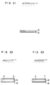
- Example 22 the same composition as in Example 15 was poured into a cell constituted by an ordinary glass plate 5, an ultraviolet-absorbing glass plate 4 containing 5% by weight of TiO2 and a spacer 8 of 1 mm in thickness. Then, the composition was cured in the same manner as in Example 1 to obtain a cured sheet 3 where the ordinary glass plate side was directed toward the irradiation light. The sheet was measured for light transmittances, haze percentage and ⁇ YI. The results are shown in Table 4.
- Example 15 the same resin composition as in Example 15 was poured into a cell constituted by an acrylic resin sheet 7 containing no ultraviolet absorber, an acrylic resin sheet 6 containing an ultraviolet absorber and a spacer 8 of 1 mm in thickness.
- the composition was cured in the same manner as in Example 1 to obtain a cured sheet 3, where the acrylic resin sheet containing no ultraviolet absorber was directed toward the irradiation light.
- the sheet was measured for light transmittances, haze percentage and ⁇ YI. The results are shown in Table 4.
- Example 15 As shown in Fig. 24, the same composition as in Example 15 was poured into a cell constituted by two ordinary glass plates 5 and a spacer 8 of 1 mm in thickness. The composition was cured in the same manner as in Example 16 to obtain a cured sheets 3. The sheet was measured for light transmittances, haze percentage and ⁇ YI. The results are shown in Table 4.
- composition consisting of 100 parts of a polyether-urethane acrylate having the refractive index of 1.481 obtained by the reaction between a polypropylene glycol having an average molecular weight of 2000, hydroxyethyl acrylate and isophorone diisocyanate, 100 parts of tribromophenoxyethyl acrylate having the refractive index of 1.567 and 6 parts of hydroxyisobutylphenone.
- the composition was poured between two horizontally placed square glass plates 4 and 4 each of 10 cm x 10 cm having a spacer 5 of 1 mm in thickness between them to form a film 3.
- a bar-shaped ultraviolet lamp 1 (80 W/cm, 2 KW, 2 cm in diameter and 25 cm in length) was provided at a distance of 40 cm in a direction perpendicular to the center of the glass plate surface so that the lamp became horizontal and parallel to the sides ab of the glass plates.
- a photomask 7 having a transmitting portion of letter A shape was placed on the glass plate surface.
- An ultraviolet lamp was irradiated from the lamp 1 at a visual angle A of 17.4° and a visual angle B of 1.4° to cure the portion of the composition film corresponding to the letter A. Then, the photomask was removed and, as shown in Fig. 26 marked similar to Fig.
- the letter A portion and the other portions were measured for total light transmittance and scattered light transmittance, and the haze percentages of the respective portions were calculated.
- a number of haze percentages were obtained by rotating the light control sheet along an axis parallel to the side ab to allow a light to enter from directions perpendicular to the side ab and thereby changing the angle of the incident light against the light control sheet.
- the angle dependency of haze percentage is shown in Fig. 27.
- the dotted line represents the haze percentages of the letter A portion and the solid line those of the other portions.
- composition consisting of 100 parts of a polyether-urethane acrylate obtained by the reaction between a polytetramethylene ether glycol, toluene diisocyanate and hydroxyethyl acrylate, 100 parts of tribromophenyl methacrylate and 6 parts of benzyl dimethyl ketal.
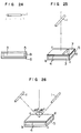
- the composition was poured between horizontally placed two square glass plates 4 each of 20 cm x 20 cm having a spacer 5 of 1 mm in thickness between them to form a resin film, as shown in Fig. 28.
- To the glass surface were attached three opaque seals 8 having A, B and C letter shapes, respectively.
- the glass plate having the seals was kept horizontally and a frosted glass plate 6 was placed thereon.
- a bar-shaped high-pressure mercury lamp (80 W/cm, 2 KW, 2 cm in diameter, 25 cm in length) was provided horizontally at a height of 40 cm, and a scattered ultraviolet light was irradiated on the film for 1 minute. Then, the frosted glass plate was removed and the seal A was stripped. As shown in Fig. 29, the same ultraviolet lamp was provided just above the letter A portion so that the lengthwise direction of the lamp became parallel to the side ab of the glass plate, and ultraviolet irradiation was conducted for 1 minute at a visual angle A of 17.4° and a visual angle B of 1.4° to cure the letter A portion. Next, the seal B was stripped, and as shown in Fig.
- the same ultraviolet irradiation was conducted from a lamp position of left 45° from a direction just above the letter B portion (the lamp was also parallel to the side ab).
- the seal C was stripped, and as shown in Fig. 31, a point type ultrahigh-pressure mercury lamp 2 (2 cm x 2 cm in light-emitting dimension) was provided 40 cm just above the letter C portion.
- An ultraviolet light was irradiated for 2 minutes at a visual angle A of 1.4° and a visual angle B of 1.4°.
- the letter A portion was cloudy when observed from just above and transparent when observed from a position at least 30° away from just above to the left or the right;
- the letter B portion was cloudy when observed from a position 45° away from just above to the left and transparent when observed from the position at least 30° away from a position tilted 45°C to the left or the right;
- the letter C portion was cloudy from all directions; and all other portions were transparent from all directions.
- the degree of transparency or cloudiness remained same when the sheet was tilted upward or downward and the degree changed only when the sheet was tilted leftward or rightward.
- the angle dependency of haze percentage of the sheet is shown in Fig. 32.
- the dotted line represents the haze percentages of the letter A portion;
- the solid line represents the haze percentages of the letter B portion;
- the line - . - . - represents the haze percentage of the letter C portion.
- a bar-shaped ultraviolet lamp 1 (80 W/cm, 2 KW, 2 cm in diameter, 25 cm in length) was provided at a height of 40 cm at a position 45° away to the right from a perpendicular to the glass plate surface passing the plate center so that the lengthwise direction of the lamp became almost parallel to the sides ab of the glass plates.
- another bar-shaped ultraviolet lamp of same type was provided at a distance of 40 cm at a position 45° away to the right from the same perpendicular so that the lengthwise direction of the lamp became almost parallel to the sides ab of the glass plates.
- a photomask 5 containing an ultraviolet light-transmitting letter X portion and a photomask containing an ultraviolet light-transmitting letter Y portion were placed on the upper and lower surfaces of the glass plates, respectively.
- Ultraviolet lights were irradiated for about 1 minute from the two lamps at a visual angle A of 12.4° and a visual angle B of 1.0°.
- the photomask X was removed and instead a frosted glass plate was placed.
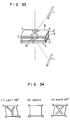
- An ultraviolet light was irradiated from just above the glass plate to cure the uncured portions with a scattered light.
- the thus obtained light control sheet 3 as shown in Fig. 34, all the portions were transparent when observed from just above [Fig. 34 (2)]; the letter Y portion was hazy and all other portions were transparent when observed from left 45° [Fig. 34 (1)]; and the letter X portion was hazy and all other portions were transparent when observed from right 45° [Fig. 34 (3)].
- Fig. 35 The angle dependency of haze percentage of the sheet is shown in Fig. 35.
- the dotted line represents the haze percentages of the letter X portion and the letter Y portion
- the solid line represents the haze percentages of all other portions.
- a mixture consisting of 100 parts of a bisphenol A type epoxy acrylate, 100 parts of tetrafluoro acrylate, 6 parts of benzyl dimethyl ketal and 3 parts of benzoyl peroxide was poured between two equare glass plates each of 10 cm x 10 cm having a gap of 1 mm, to form a resin film.
- the same bar-shaped ultraviolet lamp (80 W/cm) as used in Example 20 was provided just above the center of the glass plate surface at a perpendicular distance of 40 cm so that the lengthwise direction of the lamp became parallel to the sides ab of the glass plates.
- two bar-shaped ultraviolet lamps were provided at a perpendicular distance of 40 cm at positions 45° away to the left and the right from a perpendicular to the glass plate surfaces passing the centers of the plates so that the lengthwise directions of the lamps became parallel to the sides ab of the plates.
- a photomask containing an ultraviolet-transmitting letter X portion and a photomask containing an ultraviolet-transmitting letter Y portion were placed on the upper and lower surfaces of the glass plates. Ultraviolet lights were simultaneously irradiated from the three lamps for about 1 minute. The photomasks were removed and the glass plates were heated to 80°C to cure the uncured portions of the film.
- the letter X portion was hazy and the other portions were transparent when observed from just above [Fig. 37 (2)]; the letter Y portion was hazy and the other portions were transparent when tilted 45° rightward or leftward from a direction perpendicular to the glass plate surfaces [Fig. 37 (1) and (3)]; and all other portions were transparent from all directions.
- the angle dependency of haze percentage of the sheet is shown in Fig. 38.
- the dotted line represents the haze percentages of the letter X portion;
- the solid line represents the haze percentages of the letter Y portion;
- the same bar-shaped ultraviolet lamp (80 W/cm) as used in Example 20 was provided at a direction of a perpendicular to the glass plate surfaces passing the plate centers, at a distance of 40 cm so that the lengthwise direction of the lamp became parallel to the sides ab of the plates.
- another bar-shaped ultraviolet lamp was provided at a direction of the same perpendicular at a distance of 40 cm so that the lengthwise direction of the lamp became parallel to the sides ab of the plates.
- a photomask containing an ultraviolet-transmitting letter X portion was placed on the upper surface of the plates, and a same type photomask was placed on the lower surface of the plates so that the two X letters overlapped almost but deviated only slightly.
Landscapes
- Physics & Mathematics (AREA)
- General Physics & Mathematics (AREA)
- Optics & Photonics (AREA)
- Engineering & Computer Science (AREA)
- Manufacturing & Machinery (AREA)
- Optical Elements Other Than Lenses (AREA)
Claims (6)
- Procédé pour préparer une plaque (2, 3, 4) pour contrôle de lumière, capable de disperser une lumière incidente (IA; AI) d'angle d'incidence particulier (y1, y2), qui comprend les étapes de préparation d'un premier film (1, 3) d'une composition comprenant au moins deux constituants photopolymérisables ayant différents indices de réfraction, et d'irradiation sur au moins une partie dudit premier film par une lumière à partir d'au moins une source lumineuse (5) pour obtenir un premier film durci, caractérisé en ce que ladite source lumineuse (5) est positionnée par rapport audit premier film de sorte qu'elle ait, en premier lieu, une forme allongée, vue dudit premier film, et en second lieu, qu'elle soit vue de la région du film recevant l'irradiation sous un angle visuel A d'au moins 8° dans la direction d'axe principal de la source lumineuse, et sous un angle visuel A/4 ou inférieur dans la direction d'axe secondaire de la source lumineuse et, en troisième lieu, que la lumière de ladite source lumineuse irradie la surface (2) de ladite partie dudit premier film (1, 3) sous un premier angle d'incidence (Z); et en ce que lesdits constituants photopolymérisables sont choisis, en premier lieu, de manière à ce que la différence d'indices de réfraction d'au moins deux desdits constituants photopolymérisables soit d'au moins 0,01, et en second lieu, de manière à éviter, d'une part, la séparation de phases de la composition avant le photodurcissement et, d'autre part, un mélange complètement uniforme.
- Procédé selon la revendication 1, comprenant de plus les étapes de préparation, sur le premier film durci, d'un second film d'une composition comprenant au moins deux constituants photopolymérisables ayant différents indices de réfraction, et d'irradiation sur ledit second film par une lumière sous un second angle d'incidence différent dudit premier angle d'incidence pour obtenir un second film durci sur le premier film durci.
- Procédé selon la revendication 2, comprenant de plus les étapes de préparation sur ledit second film durci d'un troisième film d'une composition comprenant au moins deux constituants photopolymérisables ayant différents indices de réfraction, et d'irradiation sur ledit troisième film par une lumière sous un troisième angle d'incidence différent dudit premier et dudit second angles d'incidence pour obtenir un troisième film durci sur ledit second film durci.
- Procédé selon la revendication 1, caractérisé en ce qu'une pluralité de lumières provenant chacune d'une pluralité de sources lumineuses (1) apportées indépendamment les unes des autres irradient simultanément ledit premier film pour obtenir ledit premier film durci.
- Procédé selon la revendication 1, comprenant de plus les étapes de durcissement d'au moins une partie autre que ladite partie dudit premier film par irradiation par une lumière sous un angle d'incidence différent dudit premier angle d'incidence ou par tout autre procédé de durcissement, dans lequel le film durci résultant comporte au moins une partie capable de disperser une première lumière incidente d'angle d'incidence particulier, et au moins une autre partie qui est capable de disperser une seconde lumière incidente d'angle d'incidence particulier différent de celui de la première lumière incidente ou qui est totalement opaque ou totalement transparente.
- Procédé selon la revendication 1, caractérisé en ce qu'un premier photomasque (7) d'une première forme est disposé sur une face dudit premier film entre ladite partie et ladite source lumineuse , et en ce qu'un second photomasque (8) d'une seconde forme est disposé sur l'autre face dudit premier film entre une partie dudit premier film autre que ladite partie et une seconde source lumineuse, lesdites parties étant simultanément irradiées par la lumière à partir des sources lumineuses respectives à travers les photomasques respectifs pour obtenir deux parties durcies ayant la première forme et la seconde forme, respectivement, dans lequel le film durci résultant présente une partie ayant une première forme, capable de disperser une lumière incidente d'angle d'incidence particulier, et une autre partie ayant une seconde forme, capable de disperser une lumière incidente d'angle d'incidence particulier différent de celui de la partie précédente, dans lesquelles les deux parties peuvent partiellement se recouvrir l'une l'autre.
Applications Claiming Priority (14)
| Application Number | Priority Date | Filing Date | Title |
|---|---|---|---|
| JP302500/86 | 1986-12-18 | ||
| JP30250086 | 1986-12-18 | ||
| JP146564/87 | 1987-06-11 | ||
| JP14656487 | 1987-06-11 | ||
| JP62146565A JPH0758361B2 (ja) | 1987-06-11 | 1987-06-11 | 光制御板およびその製造方法 |
| JP146565/87 | 1987-06-11 | ||
| JP19783487A JP2547417B2 (ja) | 1987-08-07 | 1987-08-07 | 光制御板の製造方法 |
| JP197836/87 | 1987-08-07 | ||
| JP62197837A JP2547419B2 (ja) | 1987-08-07 | 1987-08-07 | 光制御板の製造方法 |
| JP197837/87 | 1987-08-07 | ||
| JP197833/87 | 1987-08-07 | ||
| JP62197833A JP2547416B2 (ja) | 1987-08-07 | 1987-08-07 | 光制御板の製造方法 |
| JP62197836A JP2547418B2 (ja) | 1987-08-07 | 1987-08-07 | 光制御板の製造方法 |
| JP197834/87 | 1987-08-07 |
Publications (3)
| Publication Number | Publication Date |
|---|---|
| EP0272582A2 EP0272582A2 (fr) | 1988-06-29 |
| EP0272582A3 EP0272582A3 (en) | 1990-05-16 |
| EP0272582B1 true EP0272582B1 (fr) | 1994-05-18 |
Family
ID=27566106
Family Applications (1)
| Application Number | Title | Priority Date | Filing Date |
|---|---|---|---|
| EP87118568A Expired - Lifetime EP0272582B1 (fr) | 1986-12-18 | 1987-12-15 | Plaques pour contrôle de lumière |
Country Status (5)
| Country | Link |
|---|---|
| US (2) | US4929523A (fr) |
| EP (1) | EP0272582B1 (fr) |
| KR (1) | KR960002304B1 (fr) |
| CA (1) | CA1321908C (fr) |
| DE (1) | DE3789858T2 (fr) |
Families Citing this family (71)
| Publication number | Priority date | Publication date | Assignee | Title |
|---|---|---|---|---|
| DE3789858T2 (de) * | 1986-12-18 | 1994-09-01 | Sumitomo Chemical Co | Platten für Lichtkontrolle. |
| US5112722A (en) * | 1989-04-12 | 1992-05-12 | Nippon Sheet Glass Co., Ltd. | Method of producing light control plate which induces scattering of light at different angles |
| US5104210A (en) * | 1989-04-24 | 1992-04-14 | Monsanto Company | Light control films and method of making |
| EP0409396B1 (fr) * | 1989-06-05 | 1995-09-06 | Nippon Sheet Glass Co. Ltd. | Procédé de fabrication d'une plaque de contrôle de la lumière ayant une région transparente dispersant la lumière |
| US5137801A (en) * | 1989-06-05 | 1992-08-11 | Nippon Sheet Glass Co., Ltd. | Process for producing light control plate having light-scattering pervious region |
| JP2987595B2 (ja) * | 1989-06-15 | 1999-12-06 | 住友化学工業株式会社 | 光制御板 |
| US5040870A (en) * | 1989-10-13 | 1991-08-20 | Sumitomo Chemical Company, Limited | Screen for projection |
| US5153260A (en) * | 1989-11-30 | 1992-10-06 | Sumitomo Chemical Company, Limited | Resin compositions for light control sheets, and light control sheets prepared from said compositions |
| EP0541912B1 (fr) | 1991-09-13 | 1999-07-21 | Sharp Corporation | Système électro-optique |
| KR950704703A (ko) * | 1993-08-25 | 1995-11-20 | 고오사이 아끼오 | 액정 표시 장치용 필터(filter for liquid crystal display element) |
| US5767935A (en) * | 1995-08-31 | 1998-06-16 | Sumitomo Chemical Company, Limited | Light control sheet and liquid crystal display device comprising the same |
| DE69624774T2 (de) * | 1995-12-05 | 2003-03-27 | Matsushita Electric Ind Co Ltd | Hintergrundbeleuchtete Farbanzeige |
| JP3764205B2 (ja) | 1996-04-10 | 2006-04-05 | 株式会社きもと | 視界制御シートの製造方法 |
| TW469357B (en) | 1996-08-05 | 2001-12-21 | Teijin Ltd | Alignment film with pores |
| US6010747A (en) | 1996-12-02 | 2000-01-04 | Alliedsignal Inc. | Process for making optical structures for diffusing light |
| JP3760603B2 (ja) * | 1997-10-31 | 2006-03-29 | 住友化学株式会社 | 光制御板の製造方法 |
| US6350048B1 (en) | 2000-02-03 | 2002-02-26 | William H. Stanton | Passenger lighting system for mass transit vehicle |
| JP2002318311A (ja) * | 2001-04-20 | 2002-10-31 | Clariant (Japan) Kk | 制御された散乱・透過特性を有する光学フィルム |
| US7514039B2 (en) * | 2001-07-18 | 2009-04-07 | Loomis Charles E | System and method for detection of a target substance |
| KR100949870B1 (ko) * | 2001-12-17 | 2010-03-25 | 다이셀 가가꾸 고교 가부시끼가이샤 | 방현성 필름, 및 이를 이용한 광학 부재 및 액정디스플레이 장치 |
| JP2003202415A (ja) * | 2001-12-28 | 2003-07-18 | Clariant Internatl Ltd | 制御された散乱・透過特性を有する光学フィルムおよびそれを用いた液晶表示装置 |
| TW200600825A (en) * | 2004-03-16 | 2006-01-01 | Tomoegawa Paper Co Ltd | Anisotropic light diffusion medium and production method therefor |
| JP4665457B2 (ja) | 2004-03-31 | 2011-04-06 | 住友化学株式会社 | プロジェクション用スクリーン |
| JP2005352404A (ja) | 2004-06-14 | 2005-12-22 | Nitto Denko Corp | 広視野角補償偏光板、液晶パネルおよび液晶表示装置 |
| BE1016540A3 (fr) | 2005-03-10 | 2007-01-09 | Glaverbel | Vitrage automobile a diffusion selective. |
| JP4664260B2 (ja) * | 2005-09-21 | 2011-04-06 | シャープ株式会社 | 表示装置 |
| BRPI0620259A2 (pt) * | 2005-12-23 | 2011-11-08 | British Airways Plc | assento para passageiro de aeronave |
| JP2007219027A (ja) * | 2006-02-14 | 2007-08-30 | Tomoegawa Paper Co Ltd | 異方散乱粘着部材 |
| US7800719B2 (en) * | 2006-02-17 | 2010-09-21 | Sharp Kabushiki Kaisha | Display |
| JP5354771B2 (ja) * | 2008-09-05 | 2013-11-27 | 富士フイルム株式会社 | 樹脂構造体の製造方法 |
| US8968877B2 (en) | 2011-02-16 | 2015-03-03 | Honeywell International Inc. | Barrier materials for mirror assemblies |
| KR102001274B1 (ko) | 2012-01-19 | 2019-07-17 | 린텍 가부시키가이샤 | 이방성 광확산 필름 |
| CN103946728B (zh) | 2012-01-19 | 2017-06-27 | 琳得科株式会社 | 光扩散膜的制造方法和光扩散膜 |
| WO2014079478A1 (fr) | 2012-11-20 | 2014-05-30 | Light In Light Srl | Traitement par laser à grande vitesse de matériaux transparents |
| KR102045391B1 (ko) | 2012-11-29 | 2019-11-15 | 가부시키가이샤 도모에가와 세이시쇼 | 이방성 광학 필름 |
| JP5695633B2 (ja) | 2012-12-07 | 2015-04-08 | 株式会社巴川製紙所 | 表示装置 |
| EP2754524B1 (fr) | 2013-01-15 | 2015-11-25 | Corning Laser Technologies GmbH | Procédé et dispositif destinés au traitement basé sur laser de substrats plats, galette ou élément en verre, utilisant un faisceau laser en ligne |
| EP2781296B1 (fr) | 2013-03-21 | 2020-10-21 | Corning Laser Technologies GmbH | Dispositif et procédé de découpe de contours à partir de substrats plats au moyen d'un laser |
| US11556039B2 (en) | 2013-12-17 | 2023-01-17 | Corning Incorporated | Electrochromic coated glass articles and methods for laser processing the same |
| US9850160B2 (en) | 2013-12-17 | 2017-12-26 | Corning Incorporated | Laser cutting of display glass compositions |
| US9815730B2 (en) | 2013-12-17 | 2017-11-14 | Corning Incorporated | Processing 3D shaped transparent brittle substrate |
| US9676167B2 (en) | 2013-12-17 | 2017-06-13 | Corning Incorporated | Laser processing of sapphire substrate and related applications |
| US20150165560A1 (en) | 2013-12-17 | 2015-06-18 | Corning Incorporated | Laser processing of slots and holes |
| US10442719B2 (en) | 2013-12-17 | 2019-10-15 | Corning Incorporated | Edge chamfering methods |
| US9517963B2 (en) | 2013-12-17 | 2016-12-13 | Corning Incorporated | Method for rapid laser drilling of holes in glass and products made therefrom |
| US9701563B2 (en) | 2013-12-17 | 2017-07-11 | Corning Incorporated | Laser cut composite glass article and method of cutting |
| JP2017521259A (ja) | 2014-07-08 | 2017-08-03 | コーニング インコーポレイテッド | 材料をレーザ加工するための方法および装置 |
| US10335902B2 (en) | 2014-07-14 | 2019-07-02 | Corning Incorporated | Method and system for arresting crack propagation |
| US11648623B2 (en) * | 2014-07-14 | 2023-05-16 | Corning Incorporated | Systems and methods for processing transparent materials using adjustable laser beam focal lines |
| JP6788571B2 (ja) | 2014-07-14 | 2020-11-25 | コーニング インコーポレイテッド | 界面ブロック、そのような界面ブロックを使用する、ある波長範囲内で透過する基板を切断するためのシステムおよび方法 |
| CN208586209U (zh) | 2014-07-14 | 2019-03-08 | 康宁股份有限公司 | 一种用于在工件中形成限定轮廓的多个缺陷的系统 |
| US10047001B2 (en) | 2014-12-04 | 2018-08-14 | Corning Incorporated | Glass cutting systems and methods using non-diffracting laser beams |
| KR20170105562A (ko) | 2015-01-12 | 2017-09-19 | 코닝 인코포레이티드 | 다중 광자 흡수 방법을 사용한 열적 템퍼링된 기판의 레이저 절단 |
| WO2016138054A1 (fr) | 2015-02-27 | 2016-09-01 | Corning Incorporated | Ensemble optique ayant des micro-paralumes |
| EP3848334A1 (fr) | 2015-03-24 | 2021-07-14 | Corning Incorporated | Article de verre boroaluminosilicaté d'alcalinoterreux avec un bord découpé au laser |
| EP3274313A1 (fr) | 2015-03-27 | 2018-01-31 | Corning Incorporated | Fenêtre perméable aux gaz et procédé de fabrication associé |
| CN107835794A (zh) | 2015-07-10 | 2018-03-23 | 康宁股份有限公司 | 在挠性基材板中连续制造孔的方法和与此相关的产品 |
| KR20220078719A (ko) | 2016-05-06 | 2022-06-10 | 코닝 인코포레이티드 | 투명 기판들로부터의 윤곽 형상들의 레이저 절단 및 제거 |
| US10410883B2 (en) | 2016-06-01 | 2019-09-10 | Corning Incorporated | Articles and methods of forming vias in substrates |
| US10794679B2 (en) | 2016-06-29 | 2020-10-06 | Corning Incorporated | Method and system for measuring geometric parameters of through holes |
| JP7090594B2 (ja) | 2016-07-29 | 2022-06-24 | コーニング インコーポレイテッド | レーザ加工するための装置および方法 |
| KR102423775B1 (ko) | 2016-08-30 | 2022-07-22 | 코닝 인코포레이티드 | 투명 재료의 레이저 가공 |
| WO2018064409A1 (fr) | 2016-09-30 | 2018-04-05 | Corning Incorporated | Appareils et procédés de traitement au laser de pièces transparentes au moyen de points de faisceau non axisymétriques |
| EP3848333A1 (fr) | 2016-10-24 | 2021-07-14 | Corning Incorporated | Station de traitement de substrat pour usinage laser de substrats de verre en forme de feuille |
| US10752534B2 (en) | 2016-11-01 | 2020-08-25 | Corning Incorporated | Apparatuses and methods for laser processing laminate workpiece stacks |
| US10688599B2 (en) | 2017-02-09 | 2020-06-23 | Corning Incorporated | Apparatus and methods for laser processing transparent workpieces using phase shifted focal lines |
| US10580725B2 (en) | 2017-05-25 | 2020-03-03 | Corning Incorporated | Articles having vias with geometry attributes and methods for fabricating the same |
| US11078112B2 (en) | 2017-05-25 | 2021-08-03 | Corning Incorporated | Silica-containing substrates with vias having an axially variable sidewall taper and methods for forming the same |
| US10626040B2 (en) | 2017-06-15 | 2020-04-21 | Corning Incorporated | Articles capable of individual singulation |
| US11554984B2 (en) | 2018-02-22 | 2023-01-17 | Corning Incorporated | Alkali-free borosilicate glasses with low post-HF etch roughness |
| WO2020130943A1 (fr) * | 2018-12-17 | 2020-06-25 | Agency For Science, Technology And Research | Fabrication rapide de films et de plaques de polymère à sélection angulaire transparente |
Citations (1)
| Publication number | Priority date | Publication date | Assignee | Title |
|---|---|---|---|---|
| EP0066745A2 (fr) * | 1981-05-18 | 1982-12-15 | Asahi Kasei Kogyo Kabushiki Kaisha | Ecran de protection contre la lumière et des réflexions et méthode de fabrication |
Family Cites Families (11)
| Publication number | Priority date | Publication date | Assignee | Title |
|---|---|---|---|---|
| US3811751A (en) * | 1973-04-02 | 1974-05-21 | Hughes Aircraft Co | Self-illuminated liquid crystal display panel |
| US3863246A (en) * | 1973-07-09 | 1975-01-28 | Collins Radio Co | Backlighted display apparatus for preventing direct viewing of light sources |
| JPS5981625A (ja) * | 1983-09-05 | 1984-05-11 | Canon Inc | 光拡散反射体 |
| CA1270934A (fr) * | 1985-03-20 | 1990-06-26 | Masataka Shirasaki | Masques a modulation de phase spatiale et methodes de fabrication de ces masques et de reseaux de diffraction a dephasage |
| JPS6265957A (ja) * | 1985-09-13 | 1987-03-25 | Nissan Motor Co Ltd | フオトクロミツク性を有する遮光ガラス |
| DE3689606T2 (de) * | 1985-10-22 | 1994-05-19 | Kuraray Co | Herstellungsverfahren für Phasengitter vom zusammengesetzten Muster-Refraktionstyp. |
| IT1204812B (it) * | 1986-02-19 | 1989-03-10 | Siv Soc Italiana Vetro | Procedimento per la fabbricazione di una vetrata di sicurezza per autoveicoli ed edifici,e prodotto cosi' ottenuto |
| DE3789858T2 (de) * | 1986-12-18 | 1994-09-01 | Sumitomo Chemical Co | Platten für Lichtkontrolle. |
| US4970129A (en) * | 1986-12-19 | 1990-11-13 | Polaroid Corporation | Holograms |
| JP2601832B2 (ja) * | 1987-08-07 | 1997-04-16 | 日本板硝子株式会社 | 模様入り板の製造法 |
| JPH0795122B2 (ja) * | 1987-09-24 | 1995-10-11 | 住友化学工業株式会社 | 光制御熱線吸収体 |
-
1987
- 1987-12-15 DE DE3789858T patent/DE3789858T2/de not_active Expired - Fee Related
- 1987-12-15 EP EP87118568A patent/EP0272582B1/fr not_active Expired - Lifetime
- 1987-12-16 US US07/133,603 patent/US4929523A/en not_active Expired - Lifetime
- 1987-12-17 CA CA000554584A patent/CA1321908C/fr not_active Expired - Fee Related
- 1987-12-18 KR KR1019870014530A patent/KR960002304B1/ko not_active IP Right Cessation
-
1990
- 1990-04-05 US US07/505,358 patent/US5108857A/en not_active Expired - Lifetime
Patent Citations (1)
| Publication number | Priority date | Publication date | Assignee | Title |
|---|---|---|---|---|
| EP0066745A2 (fr) * | 1981-05-18 | 1982-12-15 | Asahi Kasei Kogyo Kabushiki Kaisha | Ecran de protection contre la lumière et des réflexions et méthode de fabrication |
Also Published As
| Publication number | Publication date |
|---|---|
| DE3789858D1 (de) | 1994-06-23 |
| US5108857A (en) | 1992-04-28 |
| KR960002304B1 (ko) | 1996-02-16 |
| DE3789858T2 (de) | 1994-09-01 |
| CA1321908C (fr) | 1993-09-07 |
| KR880008047A (ko) | 1988-08-30 |
| US4929523A (en) | 1990-05-29 |
| EP0272582A3 (en) | 1990-05-16 |
| EP0272582A2 (fr) | 1988-06-29 |
Similar Documents
| Publication | Publication Date | Title |
|---|---|---|
| EP0272582B1 (fr) | Plaques pour contrôle de lumière | |
| EP0392868B1 (fr) | Méthode de fabrication d'une plaque pour contrôler la lumière à des angles différents | |
| JP2691543B2 (ja) | 光制御板およびその製造方法 | |
| JP3178091B2 (ja) | 光重合性組成物及び光制御板の製造方法 | |
| KR100434925B1 (ko) | 광학필터와그필터를장착한액정표시장치및,그액정표시장치의시야각의확대방법 | |
| US5040870A (en) | Screen for projection | |
| JP2006323379A (ja) | 光制御膜の製造方法 | |
| JPS63309902A (ja) | 光制御板およびその製造方法 | |
| JP2837239B2 (ja) | 光散乱透過性領域を備えた光制御板の製造法 | |
| JP2945939B2 (ja) | 光制御板の製造方法 | |
| JPH0267501A (ja) | 光制御板の製造方法 | |
| JP3211381B2 (ja) | 光制御板の製造方法 | |
| JPH0251101A (ja) | 光制御板及びその製造方法 | |
| JP2782200B2 (ja) | 光制御板用の樹脂組成物 | |
| JP2547417B2 (ja) | 光制御板の製造方法 | |
| JP2547416B2 (ja) | 光制御板の製造方法 | |
| US5137801A (en) | Process for producing light control plate having light-scattering pervious region | |
| JPH01147406A (ja) | 光制御板用の樹脂組成物 | |
| EP0409396B1 (fr) | Procédé de fabrication d'une plaque de contrôle de la lumière ayant une région transparente dispersant la lumière | |
| JP2547419B2 (ja) | 光制御板の製造方法 | |
| JP2822065B2 (ja) | 光制御板の製造法 | |
| JPH03200949A (ja) | プロジェクション用スクリーン | |
| KR20060111386A (ko) | 광제어 필름 제조방법 | |
| JP2837229B2 (ja) | 光制御板の製造法 | |
| EP2060558A1 (fr) | Dérivés de phényl acrylate et leur utilisation pour la production de film optique par photopolymérisation |
Legal Events
| Date | Code | Title | Description |
|---|---|---|---|
| PUAI | Public reference made under article 153(3) epc to a published international application that has entered the european phase |
Free format text: ORIGINAL CODE: 0009012 |
|
| AK | Designated contracting states |
Kind code of ref document: A2 Designated state(s): BE DE FR GB IT |
|
| RAP1 | Party data changed (applicant data changed or rights of an application transferred) |
Owner name: NIPPON SHEET GLASS COMPANY LIMITED Owner name: SUMITOMO CHEMICAL COMPANY, LIMITED |
|
| RAP3 | Party data changed (applicant data changed or rights of an application transferred) |
Owner name: NIPPON SHEET GLASS COMPANY LIMITED Owner name: SUMITOMO CHEMICAL COMPANY, LIMITED |
|
| PUAL | Search report despatched |
Free format text: ORIGINAL CODE: 0009013 |
|
| AK | Designated contracting states |
Kind code of ref document: A3 Designated state(s): BE DE FR GB IT |
|
| 17P | Request for examination filed |
Effective date: 19900928 |
|
| 17Q | First examination report despatched |
Effective date: 19920805 |
|
| GRAA | (expected) grant |
Free format text: ORIGINAL CODE: 0009210 |
|
| ITF | It: translation for a ep patent filed |
Owner name: BARZANO' E ZANARDO ROMA S.P.A. |
|
| AK | Designated contracting states |
Kind code of ref document: B1 Designated state(s): BE DE FR GB IT |
|
| REF | Corresponds to: |
Ref document number: 3789858 Country of ref document: DE Date of ref document: 19940623 |
|
| ET | Fr: translation filed | ||
| PLBE | No opposition filed within time limit |
Free format text: ORIGINAL CODE: 0009261 |
|
| STAA | Information on the status of an ep patent application or granted ep patent |
Free format text: STATUS: NO OPPOSITION FILED WITHIN TIME LIMIT |
|
| 26N | No opposition filed | ||
| PGFP | Annual fee paid to national office [announced via postgrant information from national office to epo] |
Ref country code: FR Payment date: 20001229 Year of fee payment: 14 |
|
| PGFP | Annual fee paid to national office [announced via postgrant information from national office to epo] |
Ref country code: BE Payment date: 20010315 Year of fee payment: 14 |
|
| PG25 | Lapsed in a contracting state [announced via postgrant information from national office to epo] |
Ref country code: BE Free format text: LAPSE BECAUSE OF NON-PAYMENT OF DUE FEES Effective date: 20011231 |
|
| REG | Reference to a national code |
Ref country code: GB Ref legal event code: IF02 |
|
| BERE | Be: lapsed |
Owner name: NIPPON SHEET GLASS CYLTD Effective date: 20011231 Owner name: SUMITOMO CHEMICAL CY LTD Effective date: 20011231 |
|
| PG25 | Lapsed in a contracting state [announced via postgrant information from national office to epo] |
Ref country code: FR Free format text: LAPSE BECAUSE OF NON-PAYMENT OF DUE FEES Effective date: 20020830 |
|
| REG | Reference to a national code |
Ref country code: FR Ref legal event code: ST |
|
| PGFP | Annual fee paid to national office [announced via postgrant information from national office to epo] |
Ref country code: GB Payment date: 20041215 Year of fee payment: 18 |
|
| PGFP | Annual fee paid to national office [announced via postgrant information from national office to epo] |
Ref country code: DE Payment date: 20050225 Year of fee payment: 18 |
|
| PG25 | Lapsed in a contracting state [announced via postgrant information from national office to epo] |
Ref country code: IT Free format text: LAPSE BECAUSE OF NON-PAYMENT OF DUE FEES Effective date: 20051215 Ref country code: GB Free format text: LAPSE BECAUSE OF NON-PAYMENT OF DUE FEES Effective date: 20051215 |
|
| PG25 | Lapsed in a contracting state [announced via postgrant information from national office to epo] |
Ref country code: DE Free format text: LAPSE BECAUSE OF NON-PAYMENT OF DUE FEES Effective date: 20060701 |
|
| GBPC | Gb: european patent ceased through non-payment of renewal fee |
Effective date: 20051215 |