EP0269744A1 - Antriebsschaltung einer bildanzeigevorrichtung - Google Patents
Antriebsschaltung einer bildanzeigevorrichtung Download PDFInfo
- Publication number
- EP0269744A1 EP0269744A1 EP87902776A EP87902776A EP0269744A1 EP 0269744 A1 EP0269744 A1 EP 0269744A1 EP 87902776 A EP87902776 A EP 87902776A EP 87902776 A EP87902776 A EP 87902776A EP 0269744 A1 EP0269744 A1 EP 0269744A1
- Authority
- EP
- European Patent Office
- Prior art keywords
- pulses
- counter
- output
- circuit
- decoder
- Prior art date
- Legal status (The legal status is an assumption and is not a legal conclusion. Google has not performed a legal analysis and makes no representation as to the accuracy of the status listed.)
- Granted
Links
Images


Classifications
-
- G—PHYSICS
- G09—EDUCATION; CRYPTOGRAPHY; DISPLAY; ADVERTISING; SEALS
- G09G—ARRANGEMENTS OR CIRCUITS FOR CONTROL OF INDICATING DEVICES USING STATIC MEANS TO PRESENT VARIABLE INFORMATION
- G09G3/00—Control arrangements or circuits, of interest only in connection with visual indicators other than cathode-ray tubes
- G09G3/20—Control arrangements or circuits, of interest only in connection with visual indicators other than cathode-ray tubes for presentation of an assembly of a number of characters, e.g. a page, by composing the assembly by combination of individual elements arranged in a matrix no fixed position being assigned to or needed to be assigned to the individual characters or partial characters
- G09G3/34—Control arrangements or circuits, of interest only in connection with visual indicators other than cathode-ray tubes for presentation of an assembly of a number of characters, e.g. a page, by composing the assembly by combination of individual elements arranged in a matrix no fixed position being assigned to or needed to be assigned to the individual characters or partial characters by control of light from an independent source
- G09G3/36—Control arrangements or circuits, of interest only in connection with visual indicators other than cathode-ray tubes for presentation of an assembly of a number of characters, e.g. a page, by composing the assembly by combination of individual elements arranged in a matrix no fixed position being assigned to or needed to be assigned to the individual characters or partial characters by control of light from an independent source using liquid crystals
- G09G3/3611—Control of matrices with row and column drivers
- G09G3/3685—Details of drivers for data electrodes
- G09G3/3688—Details of drivers for data electrodes suitable for active matrices only
-
- G—PHYSICS
- G09—EDUCATION; CRYPTOGRAPHY; DISPLAY; ADVERTISING; SEALS
- G09G—ARRANGEMENTS OR CIRCUITS FOR CONTROL OF INDICATING DEVICES USING STATIC MEANS TO PRESENT VARIABLE INFORMATION
- G09G3/00—Control arrangements or circuits, of interest only in connection with visual indicators other than cathode-ray tubes
- G09G3/20—Control arrangements or circuits, of interest only in connection with visual indicators other than cathode-ray tubes for presentation of an assembly of a number of characters, e.g. a page, by composing the assembly by combination of individual elements arranged in a matrix no fixed position being assigned to or needed to be assigned to the individual characters or partial characters
- G09G3/22—Control arrangements or circuits, of interest only in connection with visual indicators other than cathode-ray tubes for presentation of an assembly of a number of characters, e.g. a page, by composing the assembly by combination of individual elements arranged in a matrix no fixed position being assigned to or needed to be assigned to the individual characters or partial characters using controlled light sources
- G09G3/30—Control arrangements or circuits, of interest only in connection with visual indicators other than cathode-ray tubes for presentation of an assembly of a number of characters, e.g. a page, by composing the assembly by combination of individual elements arranged in a matrix no fixed position being assigned to or needed to be assigned to the individual characters or partial characters using controlled light sources using electroluminescent panels
-
- G—PHYSICS
- G09—EDUCATION; CRYPTOGRAPHY; DISPLAY; ADVERTISING; SEALS
- G09G—ARRANGEMENTS OR CIRCUITS FOR CONTROL OF INDICATING DEVICES USING STATIC MEANS TO PRESENT VARIABLE INFORMATION
- G09G3/00—Control arrangements or circuits, of interest only in connection with visual indicators other than cathode-ray tubes
- G09G3/20—Control arrangements or circuits, of interest only in connection with visual indicators other than cathode-ray tubes for presentation of an assembly of a number of characters, e.g. a page, by composing the assembly by combination of individual elements arranged in a matrix no fixed position being assigned to or needed to be assigned to the individual characters or partial characters
- G09G3/34—Control arrangements or circuits, of interest only in connection with visual indicators other than cathode-ray tubes for presentation of an assembly of a number of characters, e.g. a page, by composing the assembly by combination of individual elements arranged in a matrix no fixed position being assigned to or needed to be assigned to the individual characters or partial characters by control of light from an independent source
- G09G3/36—Control arrangements or circuits, of interest only in connection with visual indicators other than cathode-ray tubes for presentation of an assembly of a number of characters, e.g. a page, by composing the assembly by combination of individual elements arranged in a matrix no fixed position being assigned to or needed to be assigned to the individual characters or partial characters by control of light from an independent source using liquid crystals
- G09G3/3611—Control of matrices with row and column drivers
- G09G3/3648—Control of matrices with row and column drivers using an active matrix
-
- G—PHYSICS
- G09—EDUCATION; CRYPTOGRAPHY; DISPLAY; ADVERTISING; SEALS
- G09G—ARRANGEMENTS OR CIRCUITS FOR CONTROL OF INDICATING DEVICES USING STATIC MEANS TO PRESENT VARIABLE INFORMATION
- G09G3/00—Control arrangements or circuits, of interest only in connection with visual indicators other than cathode-ray tubes
- G09G3/20—Control arrangements or circuits, of interest only in connection with visual indicators other than cathode-ray tubes for presentation of an assembly of a number of characters, e.g. a page, by composing the assembly by combination of individual elements arranged in a matrix no fixed position being assigned to or needed to be assigned to the individual characters or partial characters
- G09G3/34—Control arrangements or circuits, of interest only in connection with visual indicators other than cathode-ray tubes for presentation of an assembly of a number of characters, e.g. a page, by composing the assembly by combination of individual elements arranged in a matrix no fixed position being assigned to or needed to be assigned to the individual characters or partial characters by control of light from an independent source
- G09G3/36—Control arrangements or circuits, of interest only in connection with visual indicators other than cathode-ray tubes for presentation of an assembly of a number of characters, e.g. a page, by composing the assembly by combination of individual elements arranged in a matrix no fixed position being assigned to or needed to be assigned to the individual characters or partial characters by control of light from an independent source using liquid crystals
- G09G3/3611—Control of matrices with row and column drivers
- G09G3/3674—Details of drivers for scan electrodes
- G09G3/3677—Details of drivers for scan electrodes suitable for active matrices only
-
- G—PHYSICS
- G09—EDUCATION; CRYPTOGRAPHY; DISPLAY; ADVERTISING; SEALS
- G09G—ARRANGEMENTS OR CIRCUITS FOR CONTROL OF INDICATING DEVICES USING STATIC MEANS TO PRESENT VARIABLE INFORMATION
- G09G2300/00—Aspects of the constitution of display devices
- G09G2300/08—Active matrix structure, i.e. with use of active elements, inclusive of non-linear two terminal elements, in the pixels together with light emitting or modulating elements
-
- G—PHYSICS
- G09—EDUCATION; CRYPTOGRAPHY; DISPLAY; ADVERTISING; SEALS
- G09G—ARRANGEMENTS OR CIRCUITS FOR CONTROL OF INDICATING DEVICES USING STATIC MEANS TO PRESENT VARIABLE INFORMATION
- G09G2310/00—Command of the display device
- G09G2310/02—Addressing, scanning or driving the display screen or processing steps related thereto
- G09G2310/0264—Details of driving circuits
- G09G2310/0267—Details of drivers for scan electrodes, other than drivers for liquid crystal, plasma or OLED displays
-
- G—PHYSICS
- G09—EDUCATION; CRYPTOGRAPHY; DISPLAY; ADVERTISING; SEALS
- G09G—ARRANGEMENTS OR CIRCUITS FOR CONTROL OF INDICATING DEVICES USING STATIC MEANS TO PRESENT VARIABLE INFORMATION
- G09G2330/00—Aspects of power supply; Aspects of display protection and defect management
- G09G2330/08—Fault-tolerant or redundant circuits, or circuits in which repair of defects is prepared
Definitions
- the present invention relates to a driving circuit for the image display apparatus of liquid-crystal matrix panels.
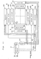
- Fig. 18 shows the driving circuit for the liquid-crystal display apparatus by the active matrix liquid-crystal panels to be used in the liquid-crystal TV apparatus.
- a circuit as described hereinabove is described in, for example, Japanese Patent Application Laid-Open Publication Tokkaisho No. 57-41078.
- the liquid-crystal panel 1 of the active matrix type has n column of picture elements in the X direction and m row of picture elements in the Y direction.
- the TFTs (thin film transistors) la composed of m x n amorphous silicone (a-Si) and the liquid-crystal electrodes lb are connected in matrix shape as shown with the respective rows Gl, G2, ... Gm and the respective columns Dl, D2, ... Dn being respectively connected with the row driver 2 and the column driver 3.
- the row driver is composed of the m stage of shift register 2a and output circuit 2b.
- the column driver is composed of the n stage of shift register 3a, the- sampling hold circuit 3b and the output circuit 3c.
- the synchronization controlling circuit 4 generates the first and second start pulses ST1 and ST2 and the first and second clock pulses CPl and CP2 in accordance with the horizontal synchronizing signal H P and the vertical synchronizing signal V P .
- the first start pulse STI synchronized with the vertical synchronizing signal and the first clock pulse CP1 synchronized with the horizontal synchronizing signal are fed into the shift register 2a, the voltage waveforms shifted 1H (1 horizontal period) by 1H are applied upon each row Gl, G2, ....
- the TFTs la of each line are sequentially turned on in the horizontal retrace section by the voltage waveform to apply the liquid-crystal driving voltage upon each picture element.
- the column driver repeats the same operation in each 1H section.
- Each stage of the sample holding circuit 3b is controlled by the output of the shift register of each of the corresponding stages, the voltage value of the image signal is sampled by the falling of the output to hold it till the sampling time (for 1H).
- the output circuit 3c receives the output of the sampling hold circuit to buffer-amplify to drive the column electrode.
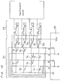
- the shift register in the above-described driving circuit is of such construction as shown in Fig. 19.
- the transfer of the data is performed through the sequential switching operation of four transistors per stage of the shift register by clock ⁇ , I, the delay time per stage of transistor is required to be within one fourth of the clock period for the operation.
- the transistor of the slow switching speed like the a-Si TFT in use for the liquid-crystal panel 1 can not be used.
- an object of the present invention is to provide a transistor of comparatively slow switching speed in one portion of the driving circuit.
- Another object of the present invention is to reduce the consumption power of the driving circuit.
- a further object of the present invention is to provide a driving circuit where large transient current does not flow to the output circuit when the output signal is switched, and the switching time does not become long.
- a still further object of the present invention is to properly operate the panel and to improve the yield even if something goes wrong with the matrix panel or the driving circuit.
- the present invention provides a driving circuit for the image display apparatus, wherein the respective rows and columns of the active matrix panel with a plurality of picture elements being disposed in the matrix shape are respectively selected by the clock pulses of the given frequency to drive each of the picture elements.
- the present invention is characterized in that a counter for counting the clock pulses to introduce the binary count values and their inversion outputs, and a decoder for decoding the counter outputs to generate pulses, which sequentially shift in synchronous relation with the clock pulses, into the respective rows or the respective columns are provided, the switching transistor constituting the decoder is formed as a thin film transistor on the same base plate as the active matrix panel.
- the driving circuit is composed of a counter which is adapted to count the clock pulses to introduce the binary count values and their inversion outputs, a decoder which is adapted to generate the pulses that sequentially shift in synchronous relation with the clock pulses into the respective rows and/or the respective columns of the matrix panel, so that the time required for the switching operation of the switching transistor within the driving circuit is adapted to become shorter by the above-described means.
- Fig. 1 a block diagram showing -a driving circuit for a liquid-crystal display apparatus with active matrix liquid-crystal panel to be used in a liquid-crystal TV apparatus according to a first preferred embodiment of the present invention, which includes a liquid-crystal panel 1, output circuits 52, 63, a sample holding circuit 62, decoders 51, 61, a synchronization controlling circuit 4, and counters 50, 60.
- the active matrix type of liquid-crystal panel 1 has picture elements of n column in the X direction, m row in the Y direction, a TFT (thin film transistor) la and a liquid-crystal electrode lb composed of an amorphous silicon (a-Si) of m x n connected into a matrix shape as shown, the respective rows Gl, G2, ... Gm and the respective columns Dl, D2, ... Dn are respectively connected with row driver 5 and a column driver 6.
- the row driver 5 is composed of a decoder 51 and an output circuit 52
- the column driver 6 is composed of a decoder 61, a sample holding circuit 62 and an output circuit 63.
- the synchronization controlling circuit 4 generates the first and second start pulses ST1 and S T 2 and the first and second clock pulses CP1 and CP2 in accordance with horizontal synchronizing signals H P and vertical synchronizing signals Vp.
- Fig. 16 shows each waveform of the row driver 5
- reference character a shows a picture signal with a vertical synchronizing signal V and a horizontal synchronizing signal H P being placed one upon another.
- reference character T1 shows the vertical synchronizing signal section
- reference character T2 shows the vertical retrace section
- reference character T3 is the picture signal section.
- each portion waveform of the driver 6 is shown in Fig. 17.
- the column driver repeats the same operation in each 1H section.
- Fig. 17(a) is a picture signal wherein 1H section in T3 is expanded and drawn.
- reference character T4 shows a horizontal retrace section
- reference character T5 shows the picture information-contained section.
- the second start pulses ST2 synchronized with the horizontal synchronous signal shown in Figs. 17(b) and 17(c), and the second clock pulses of the frequency of the period T T5/n are fed to the counters 50 and 60.
- the counter 50 which is the first counter, starts the counting operation of the first clock pulses CP1 with the first start pulse ST1 from the synchronization controlling circuit 4 to output the binary count outputs A and B and to output the inversion outputs B.
- This counter is composed of IC:LC4520B and LC4049B manufactured by Tokyo Sanyo Electric Co., Ltd.
- the decoder 51 is the first decoder, which decodes the first counter output to respectively output the pulses that become high sequentially for each of the first clock pulses CP1 to the right and left of each row Gl, G2, ....
- the counter 60 is the second counter, which is adapted to output the binary outputs in accord- .ance with the second start pulse ST2 and the second clock pulse CP2 from the synchronization controlling circuit 4.
- the decoder 61 is the second decoder, which decodes the second counter output to output the pulses that become high sequentially for each of the second clock pulses CP2 to each column Dl, D2, ....
- the row driver 5 is composed of the first counter 50, the first decoder 51 and the output circuit 52.
- the column driver 6 is composed of the second counter 60, the second decoder 61, the sample holding circuit 62 and the output circuit 63.
- the first and second decoders 51 and 61, the output circuits 52 and 63, and the sample holding circuit 62 are formed of the a-Si TFT in the same process and on the same base plate as on the liquid-crystal panel 1.
- each row of the binary count outputs A and B from the first counter 50 and the inversion outputs A and B , and each row Gl, G2, ... are crossed in the matrix shape with two TFTs composing an AND gate being disposed in series in each row.
- each row has loads TFT T9 through T12 connected therewith.
- the output circuit 52 which has such construction as shown in Fig. 3, is connected with the outputs for each of the rows.
- Fig. 4 shows a circuit diagram of one row portion of the output circuit in the present embodiment.
- a first FET T17 for amplification and a second FET T18 for loading are longitudinally connected between the power supply V DD and an earth, the gate of the second FET T18 being connected with the power supply V DD .
- the input signal is applied upon the gate of the first FET T17 so that the output signal is outputted from the connection point between the first and second FETs T17 and T18.
- the circuit of Fig. 4 when the input signal is high, the first and second FETs T17 and T18 are turned on, thus the output becomes high. At this time, the current does flow to the output gate circuit constituted by the first and second FETs T17 and T18.
- the first and second FETs T17 and T18 are turned off, thus resulting in the low output. At this time, the current does not flow into the output gate of the first first and second FETs.
- the current flows to the output circuit of one row portion selected from among two hundred forty rows, but the current does not flow at all to the output circuit of the other two hundred thirty-nine rows.
- Fig. 5 shows the other embodiment of the output circuit, wherein the third and fourth FETs T19 and T20 for load use and amplification use are connected in the same manner as in Fig. 4 to provide the two-stage construction.
- the present invention is applied only upon the row driver. Needless to say, it may even be applied the column driver.
- Fig. 6 shows a circuit diagram of one row portion of the output circuit in the present embodiment.
- the first and second FETs T17 and T18 for amplification are longitudinally connected between the power supply V and an earth. And the input signal is applied upon the gate of the first FE T T 17 so that- the output signal is outputted from the connection point between the first and second FETs T17 and T18.
- the reversion output which has been reversed by the inverter composed of the third and fourth FETs T19 and T20 is applied upon the gate of the second FET T18.
- the operation will be described hereinafter.
- the first FET T17 is turned on.
- the fourth FET T20 also becomes high at the gate to turn on the fourth FET so as to turn off the second FET T18.
- the output becomes high.
- the comparatively small current flows to the third and fourth FETs T19 and T20 which constitute the inverter, but the current does not flow to the output gate circuit constituted by the first and second FETs T17 and T18.
- the current does not flow in the steady-state condition with the small amount of current flowing the first first and second FETs at the switching operation.
- the current flows to the output circuit of one row portion selected from among two hundred forty rows, but the current does not flow at all to the output circuit of the other two hundred thirty-nine rows.
- the power consumption in the driving circuit may be considerably reduced so as to make the image display apparatus for the liquid-crystal TV or the like smaller in size.
- Fig. 7 shows the other embodiment of the first decoder.
- the first decoder 51' of the present embodiment is a NAND gate, wherein the TFTs Tl through T8 are disposed parallel to each row, with the advantage that the driving voltage may be made lower through the power consumption and the wiring number are a little more than in Fig. 2.
- the first decoder 51' of the present embodiment is an AND gate, where the diodes Dl through D8 are disposed parallel to each row, with the advantage that the driving voltage is lower and the number of the wirings is fewer though the power consumption is large.
- the first decoder actually needs about 240 in the row number to increase the column number of the counters though the first decoder shows only four-row portion for simplification.
- the second counter 60 and the second decoder 61 in the column driver 6 are fundamentally similar in construction and operation to those of the row driver 5, they are not shown.
- one portion of the driving circuit may be construction on the same base plate as the switching transistor located within the active matrix panel and with the switching transistor of the same construction through the same process, so that the external circuit of the matrix panel may be considerably simplified and the connection wires between the matrix panel and the external circuit may be considerably reduced in number.
- Fig. 9 The other embodiment will be shown in Fig. 9 as the concrete circuit of the row driver.
- Each code signal line of the binary count outputs A, B and inversion outputs A, B from the first counter 50 is crossed .in the matrix shape with respect to the lines Ll through L4 provided corresponding to each row Gl, G2 of the matrix panel.
- the TFTs Tl through T8 constituting two AND gates are arranged for each row, so that the high is adapted to be outputted into each of the lines Ll through L4 when either of the respective rows Gl, G2, ... is selected.
- each of the code signal lines is crossed in the matrix shape with respect to the adjacently disposed lines Ll' and L4' in addition to the lines Ll through L4 corresponding to each row Gl, G4, ....
- the TFTs Tl' through T8' are arranged similarly on each line, so that the low is adapted to be outputted upon each line Ll' through L4' when either of the respective rows Gl, G2, ... is selected. Namely, the output of the opposite phase appears on the adjacent two lines L1 and Ll'.
- the output circuit 52 is composed of a pair of longitudinally connected first and second FETs T17 and T18 for each row Gl, G2, ..., -with each row Gl, G2, ... being connected from the connection point between both the FETs. And the lines Ll through L4 are combined with each gate of the first FET T17, the lines Ll' through L4' are combined with each gate of the second FET T18.
- the next row sequentially becomes high and is selected to drive the TFT within the liquid-crystal panel of that row.
- the decoder simultaneously outputs two signals opposite in phase in accordance with each row to apply the completely opposite- phase signals upon each gate of the first and second FETs, so that the current does not flow at all in the steady-state condition.
- Fig. 10 shows the other embodiment of the row driver.
- the first and second FETs T17 and T18 of the decoder 51 and the output circuit 52 are respectively divided and disposed on both the sides of the liquid-crystal panel 1 and may be symmetrically arranged at right and left.
- the current does not flow at all under the steady condition in the output circuit and the large transient current does not flow even during the switching operation, so that the power consumption of the driving circuit may be reduced. Also, the switching time does not become longer than necessary.
- Fig. 11 is a block diagram showing the driving circuit of the liquid-crystal display apparatus in the other second embodiment.
- the same reference characters are given to the same portions as in Fig. 1 with the description being omitted.
- a first counter 50 starts the counting operation of the first clock pulse CP1. by the first start pulse ST1 from the synchronization controlling circuit 4 to output the binary count outputs A, B and the inversion outputs A, B.
- the first decoders 51, 51 decode the first counter outputs to respectively output the pulses, which sequentially become high for each of the first clock pulses CP1 to the right and left of each row Gl, G2, ....
- a second counter 60 outputs the binary counter outputs in accordance with the second start pulse ST2 and the second clock pulse CP2 from the synchronization controlling circuit 4.
- the second decoders 61, 61 respectively output the pulses, which sequentially become high for each of the second clock pulses CP2 upwardly and downwardly of each column Dl, D2, ... through the decoding operation of this second counter output.
- the row driver 5 is composed of the first counter 50, the first decoder 51 and the output circuit 52.
- the column driver 6 is composed of the second counter 60, the second decoder 61, the sample holding circuit 62 and the output circuit 63.
- the first and second decoders 51 and 61, the output circuits 52 and 63, and the sample holding circuit 62 are formed on the same base plate as the liquid-crystal panel 1 and through the same process by the a-Si TFT.
- decoder 51 and the output circuit 52 are shown only in the left-hand side portion of Fig. 12, they are really arranged symmetrically in right and left as shown in Fig. 1, with one row being driven by the same signal from the right and left.
- the signals are fed into the entire rows, because the signals are fed from both the sides of the rows, so that the displaying operation is completely performed.
- the line defects may be changed into the point defects because of the cutting operation of that portion at two locations, the signal line is crossed on the scanning line.
- the fault line becomes open if the output line of the output circuit corresponding to the gate line existing between the two lines is cut with laser or the like, so that the driving operation may be effected with the signal from the other decoder.
- the operation may be effected without-hindrance if the failures such as disconnection, short-circuit or the like occur on the matrix panel or within the driving circuit during the manufacturing process, so that the yield.may be considerably improved as compared with the conventional one with the shift register being used in the driving circuit.
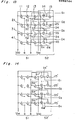
- the third embodiment wherein the driving circuit of the picture display apparatus of the present invention is shown in Fig. 13 and Fig. 14.
- the first bit a of the binary count is connected with each gate of the p type TFTs 11 and 31 of the first and third row signal lines, of the n type TFTs 21 and 41 of the second and fourth row signal lines
- the second bit b is connected with each gate of the p type TFTs 12 and 22 of the first and second row signal lines, of the n type TFTs 32 and 42 of the third and fourth row signal lines.
- the TFTs 21, 32, 41 and 42 turn off when the-counter is 0, only the first output signal gl, with the TFTs 11 and 12 of ON condition being operated, among four outputs gl through g4 from the decoder 51 becomes high. Accordingly, as the - TFT 14 turns on in the output circuit 52 composed of n channel TFTs 14, 15, 24, 25, 34, 35, 44 and 45, only the first gate Gl among four gate signals Gl through G4 becomes high.
- the output circuit 52' is different from that of the embodiment of Fig. 12. Namely, the circuit 52' complementarily connects the p channel TFTs 14, 24, 34 and 44 with the n channel TFTs 15, 25, 35 and 45. As the TFTs of the p channel TFTs or the n channel TFTs are off with the exception of the switching operation time, the current consumption is smaller.
- Fig. 15(a) The process of forming the p channel TFTs and the n channel T F Ts on the same base plate, i.e., the active matrix panel, is shown in Fig. 15.
- the conductive layer 100 composed of ITO or gold which becomes the source of the TFT and the drain electrode is attached on the-glass base plate s of the active matrix panel to perform the patterning operation on the given pattern with photo-lithography.
- the n type of amorphous silicones which become the source, drain electrodes 200, 200 of the n channel TFTs are attached to perform the patterning operation.
- the p type of amorphous silicones which becomes the source, drain electrodes 300, 300 of the p channel TFTs are attached on them to perform the patterning operation as shown in Fig. 15(c), the former n type of amorphous silicones 200, 200 may remain.
- Fig. 15 (d) the i type (genuine) amorphous silicones which become the operation regions 400 of both the TFTs are attached to perform the patterning operation.
- insulating film such as Si0 2 , si 3 N or the like which becomes the gate insulating film 5 is attached thereon.
- a conductive layer such as aluminum which becomes a gate. electrode 600 is attached to perform the patterning operation.
- the present invention is embodied about the driving circuit on the side of the gate signal line. Needless to say, it may be adopted on the driving circuit on the side of the drain signal line.
- the decoder is composed of the combination circuit between the p channel thin film transistor and the n channel thin film transistor so that the decoding operation may be-performed by the use of the binary count value from the counter without the use of the inversion output.
- the input lines from the counter into the decoder are halved in number to simplify the construction of the decoder and to improve the yield.
Landscapes
- Engineering & Computer Science (AREA)
- Physics & Mathematics (AREA)
- Computer Hardware Design (AREA)
- General Physics & Mathematics (AREA)
- Theoretical Computer Science (AREA)
- Chemical & Material Sciences (AREA)
- Crystallography & Structural Chemistry (AREA)
- Liquid Crystal Display Device Control (AREA)
- Liquid Crystal (AREA)
- Control Of Indicators Other Than Cathode Ray Tubes (AREA)
- Control Of El Displays (AREA)
Applications Claiming Priority (15)
| Application Number | Priority Date | Filing Date | Title |
|---|---|---|---|
| JP108969/86 | 1986-05-13 | ||
| JP61108969A JPH0766252B2 (ja) | 1986-05-13 | 1986-05-13 | 画像表示装置の駆動回路 |
| JP61115080A JPH0628426B2 (ja) | 1986-05-20 | 1986-05-20 | 画像表示装置の駆動回路 |
| JP115078/86 | 1986-05-20 | ||
| JP61115076A JPS62271571A (ja) | 1986-05-20 | 1986-05-20 | 画像表示装置の駆動回路 |
| JP115076/86 | 1986-05-20 | ||
| JP115079/86 | 1986-05-20 | ||
| JP115077/86 | 1986-05-20 | ||
| JP11507786A JPS62271572A (ja) | 1986-05-20 | 1986-05-20 | 画像表示装置の駆動回路 |
| JP11507886A JPH0628424B2 (ja) | 1986-05-20 | 1986-05-20 | 画像表示装置の駆動回路 |
| JP115080/86 | 1986-05-20 | ||
| JP61115079A JPH0628425B2 (ja) | 1986-05-20 | 1986-05-20 | 画像表示装置の駆動回路 |
| JP61219982A JPH0766256B2 (ja) | 1986-09-17 | 1986-09-17 | 画像表示装置 |
| JP219982/86 | 1986-09-17 | ||
| PCT/JP1987/000294 WO1987007067A1 (en) | 1986-05-13 | 1987-05-12 | Circuit for driving an image display device |
Publications (3)
| Publication Number | Publication Date |
|---|---|
| EP0269744A1 true EP0269744A1 (de) | 1988-06-08 |
| EP0269744A4 EP0269744A4 (en) | 1991-01-16 |
| EP0269744B1 EP0269744B1 (de) | 1994-12-14 |
Family
ID=27565756
Family Applications (1)
| Application Number | Title | Priority Date | Filing Date |
|---|---|---|---|
| EP87902776A Expired - Lifetime EP0269744B1 (de) | 1986-05-13 | 1987-05-12 | Antriebsschaltung einer bildanzeigevorrichtung |
Country Status (7)
| Country | Link |
|---|---|
| US (1) | US5051739A (de) |
| EP (1) | EP0269744B1 (de) |
| KR (1) | KR900009055B1 (de) |
| AU (1) | AU588693B2 (de) |
| CA (1) | CA1294075C (de) |
| DE (1) | DE3750870T2 (de) |
| WO (1) | WO1987007067A1 (de) |
Cited By (11)
| Publication number | Priority date | Publication date | Assignee | Title |
|---|---|---|---|---|
| EP0404025A2 (de) * | 1989-06-19 | 1990-12-27 | Heimann Optoelectronics GmbH | Schaltungsanordnung zur Ansteuerung von Schaltelementen, die insbesondere geeignet ist für Flüssigkristallbildschirme |
| WO1992009985A1 (fr) * | 1990-12-03 | 1992-06-11 | Thomson S.A. | Generateur a largeur d'impulsion variable comprenant un vernier temporel |
| EP0601869A2 (de) * | 1992-12-10 | 1994-06-15 | Sharp Kabushiki Kaisha | Flache Anzeigevorrichtung, ihr Ansteuerverfahren und Verfahren zu ihrer Herstellung |
| EP0793215A1 (de) * | 1996-02-27 | 1997-09-03 | Sony Corporation | Anzeigevorrichtung mit aktiver Matrix |
| EP1020840A1 (de) * | 1998-08-04 | 2000-07-19 | Seiko Epson Corporation | Elektrooptische einheit und elektronische einheit |
| US6731264B2 (en) | 1994-09-30 | 2004-05-04 | Semiconductor Energy Laboratory Co., Ltd. | Driver circuit for display device |
| US6897847B2 (en) | 1994-08-16 | 2005-05-24 | Semiconductor Energy Laboratory Co., Ltd. | Peripheral driver circuit of liquid crystal electro-optical device |
| US7656380B2 (en) | 2000-10-23 | 2010-02-02 | Semiconductor Energy Laboratory Co., Ltd. | Display device |
| US7893913B2 (en) | 2000-11-07 | 2011-02-22 | Semiconductor Energy Laboratory Co., Ltd. | Display device including a drive circuit, including a level shifter and a constant current source |
| US8373631B2 (en) | 1998-03-27 | 2013-02-12 | Semiconductor Energy Laboratory Co., Ltd. | Driving circuit of a semiconductor display device and the semiconductor display device |
| CN114141135A (zh) * | 2020-09-04 | 2022-03-04 | 乐金显示有限公司 | 显示装置 |
Families Citing this family (60)
| Publication number | Priority date | Publication date | Assignee | Title |
|---|---|---|---|---|
| JP2632974B2 (ja) * | 1988-10-28 | 1997-07-23 | キヤノン株式会社 | 駆動装置及び液晶装置 |
| DE68926885T2 (de) * | 1989-09-08 | 1997-01-09 | Canon Kk | Datenverarbeitungssystem mit Anzeigetafel |
| GB9217336D0 (en) * | 1992-08-14 | 1992-09-30 | Philips Electronics Uk Ltd | Active matrix display devices and methods for driving such |
| US5781164A (en) * | 1992-11-04 | 1998-07-14 | Kopin Corporation | Matrix display systems |
| JP3144166B2 (ja) * | 1992-11-25 | 2001-03-12 | ソニー株式会社 | 低振幅入力レベル変換回路 |
| GB9314849D0 (en) * | 1993-07-16 | 1993-09-01 | Philips Electronics Uk Ltd | Electronic devices |
| JP3197123B2 (ja) * | 1993-09-29 | 2001-08-13 | 株式会社東芝 | キャラクタ表示データ書込み装置 |
| US5729245A (en) * | 1994-03-21 | 1998-03-17 | Texas Instruments Incorporated | Alignment for display having multiple spatial light modulators |
| JP2739821B2 (ja) * | 1994-03-30 | 1998-04-15 | 日本電気株式会社 | 液晶表示装置 |
| JP3471928B2 (ja) * | 1994-10-07 | 2003-12-02 | 株式会社半導体エネルギー研究所 | アクティブマトリクス表示装置の駆動方法 |
| EP1603109A3 (de) * | 1995-02-01 | 2006-01-04 | Seiko Epson Corporation | Substrat mit aktiver Matrix und Flüssigkristallanzeigevorrichtung damit |
| JPH08263016A (ja) | 1995-03-17 | 1996-10-11 | Semiconductor Energy Lab Co Ltd | アクティブマトリクス型液晶表示装置 |
| JP3520131B2 (ja) * | 1995-05-15 | 2004-04-19 | 株式会社東芝 | 液晶表示装置 |
| JP3526992B2 (ja) * | 1995-11-06 | 2004-05-17 | 株式会社半導体エネルギー研究所 | マトリクス型表示装置 |
| JPH09146489A (ja) * | 1995-11-20 | 1997-06-06 | Sharp Corp | 走査回路および画像表示装置 |
| JP3597287B2 (ja) | 1995-11-29 | 2004-12-02 | 株式会社半導体エネルギー研究所 | 表示装置及びその駆動方法 |
| US6069600A (en) * | 1996-03-28 | 2000-05-30 | Kabushiki Kaisha Toshiba | Active matrix type liquid crystal display |
| JPH09319326A (ja) * | 1996-05-30 | 1997-12-12 | Sharp Corp | 走査回路およびマトリクス型画像表示装置 |
| US6100879A (en) * | 1996-08-27 | 2000-08-08 | Silicon Image, Inc. | System and method for controlling an active matrix display |
| JPH10198312A (ja) * | 1996-12-30 | 1998-07-31 | Semiconductor Energy Lab Co Ltd | 表示装置及び表示装置の駆動方法 |
| US6157360A (en) * | 1997-03-11 | 2000-12-05 | Silicon Image, Inc. | System and method for driving columns of an active matrix display |
| US6100868A (en) * | 1997-09-15 | 2000-08-08 | Silicon Image, Inc. | High density column drivers for an active matrix display |
| JPH11119734A (ja) * | 1997-10-08 | 1999-04-30 | Fujitsu Ltd | 液晶表示装置の駆動回路、及び液晶表示装置 |
| JPH11242204A (ja) * | 1998-02-25 | 1999-09-07 | Sony Corp | 液晶表示装置およびその駆動回路 |
| US7569849B2 (en) | 2001-02-16 | 2009-08-04 | Ignis Innovation Inc. | Pixel driver circuit and pixel circuit having the pixel driver circuit |
| JP2002311912A (ja) * | 2001-04-16 | 2002-10-25 | Hitachi Ltd | 表示装置 |
| CA2355067A1 (en) | 2001-08-15 | 2003-02-15 | Ignis Innovations Inc. | Metastability insensitive integrated thin film multiplexer |
| JP2004264361A (ja) * | 2002-03-29 | 2004-09-24 | Pioneer Electronic Corp | ディスプレイパネルの駆動装置 |
| CA2419704A1 (en) | 2003-02-24 | 2004-08-24 | Ignis Innovation Inc. | Method of manufacturing a pixel with organic light-emitting diode |
| CA2443206A1 (en) | 2003-09-23 | 2005-03-23 | Ignis Innovation Inc. | Amoled display backplanes - pixel driver circuits, array architecture, and external compensation |
| CA2472671A1 (en) | 2004-06-29 | 2005-12-29 | Ignis Innovation Inc. | Voltage-programming scheme for current-driven amoled displays |
| CA2490858A1 (en) | 2004-12-07 | 2006-06-07 | Ignis Innovation Inc. | Driving method for compensated voltage-programming of amoled displays |
| CA2495726A1 (en) | 2005-01-28 | 2006-07-28 | Ignis Innovation Inc. | Locally referenced voltage programmed pixel for amoled displays |
| US8477121B2 (en) | 2006-04-19 | 2013-07-02 | Ignis Innovation, Inc. | Stable driving scheme for active matrix displays |
| TWI344629B (en) * | 2006-08-21 | 2011-07-01 | Au Optronics Corp | Display and display panel thereof |
| US9620072B2 (en) * | 2009-01-15 | 2017-04-11 | International Business Machines Corporation | Method and apparatus for reducing power consumption of an electronic display |
| US8283967B2 (en) | 2009-11-12 | 2012-10-09 | Ignis Innovation Inc. | Stable current source for system integration to display substrate |
| WO2012156942A1 (en) | 2011-05-17 | 2012-11-22 | Ignis Innovation Inc. | Systems and methods for display systems with dynamic power control |
| US9606607B2 (en) | 2011-05-17 | 2017-03-28 | Ignis Innovation Inc. | Systems and methods for display systems with dynamic power control |
| US8901579B2 (en) | 2011-08-03 | 2014-12-02 | Ignis Innovation Inc. | Organic light emitting diode and method of manufacturing |
| US9070775B2 (en) | 2011-08-03 | 2015-06-30 | Ignis Innovations Inc. | Thin film transistor |
| US9385169B2 (en) | 2011-11-29 | 2016-07-05 | Ignis Innovation Inc. | Multi-functional active matrix organic light-emitting diode display |
| US10089924B2 (en) | 2011-11-29 | 2018-10-02 | Ignis Innovation Inc. | Structural and low-frequency non-uniformity compensation |
| US9721505B2 (en) | 2013-03-08 | 2017-08-01 | Ignis Innovation Inc. | Pixel circuits for AMOLED displays |
| US9952698B2 (en) | 2013-03-15 | 2018-04-24 | Ignis Innovation Inc. | Dynamic adjustment of touch resolutions on an AMOLED display |
| US9502653B2 (en) | 2013-12-25 | 2016-11-22 | Ignis Innovation Inc. | Electrode contacts |
| US10997901B2 (en) | 2014-02-28 | 2021-05-04 | Ignis Innovation Inc. | Display system |
| US10176752B2 (en) | 2014-03-24 | 2019-01-08 | Ignis Innovation Inc. | Integrated gate driver |
| KR102289934B1 (ko) * | 2014-11-28 | 2021-08-13 | 삼성디스플레이 주식회사 | 터치 감지 센서를 포함하는 표시 장치 |
| CA2872563A1 (en) | 2014-11-28 | 2016-05-28 | Ignis Innovation Inc. | High pixel density array architecture |
| CN104851402B (zh) * | 2015-05-27 | 2017-03-15 | 深圳市华星光电技术有限公司 | 一种多相位时钟产生电路及液晶显示面板 |
| US10373554B2 (en) | 2015-07-24 | 2019-08-06 | Ignis Innovation Inc. | Pixels and reference circuits and timing techniques |
| US10657895B2 (en) | 2015-07-24 | 2020-05-19 | Ignis Innovation Inc. | Pixels and reference circuits and timing techniques |
| CA2898282A1 (en) | 2015-07-24 | 2017-01-24 | Ignis Innovation Inc. | Hybrid calibration of current sources for current biased voltage progra mmed (cbvp) displays |
| CA2909813A1 (en) | 2015-10-26 | 2017-04-26 | Ignis Innovation Inc | High ppi pattern orientation |
| DE102017222059A1 (de) | 2016-12-06 | 2018-06-07 | Ignis Innovation Inc. | Pixelschaltungen zur Minderung von Hysterese |
| US10714018B2 (en) | 2017-05-17 | 2020-07-14 | Ignis Innovation Inc. | System and method for loading image correction data for displays |
| US11025899B2 (en) | 2017-08-11 | 2021-06-01 | Ignis Innovation Inc. | Optical correction systems and methods for correcting non-uniformity of emissive display devices |
| KR102485566B1 (ko) * | 2017-11-24 | 2023-01-09 | 삼성디스플레이 주식회사 | 게이트 구동 장치, 이를 포함하는 표시 장치 및 이를 이용한 표시 패널의 구동 방법 |
| US10971078B2 (en) | 2018-02-12 | 2021-04-06 | Ignis Innovation Inc. | Pixel measurement through data line |
Citations (3)
| Publication number | Priority date | Publication date | Assignee | Title |
|---|---|---|---|---|
| JPS54145992A (en) * | 1978-05-06 | 1979-11-14 | Kokusai Denshin Denwa Co Ltd | Cable searching system and apparatus |
| GB2155221A (en) * | 1984-02-01 | 1985-09-18 | Hitachi Ltd | A series/parallel conversion circuit and display driver |
| EP0177247A2 (de) * | 1984-09-28 | 1986-04-09 | Kabushiki Kaisha Toshiba | Aktives Matrixanzeigegerät |
Family Cites Families (13)
| Publication number | Priority date | Publication date | Assignee | Title |
|---|---|---|---|---|
| JPS53279B1 (de) * | 1971-02-25 | 1978-01-06 | ||
| GB1511239A (en) * | 1974-07-15 | 1978-05-17 | Hitachi Ltd | Driver circuit for a liquid crystal display device |
| US4114070A (en) * | 1977-03-22 | 1978-09-12 | Westinghouse Electric Corp. | Display panel with simplified thin film interconnect system |
| JPS54154992A (en) * | 1978-05-29 | 1979-12-06 | Seiko Epson Corp | Semiconductor electrode substrate for liquid crystal panel drive |
| JPS5577790A (en) * | 1978-12-08 | 1980-06-11 | Seiko Instr & Electronics | Multiplex liquid crystal display unit |
| JPS5687089A (en) * | 1979-12-17 | 1981-07-15 | Seiko Instr & Electronics | Dot matrix liquid crystal display unit |
| GB2081018B (en) * | 1980-07-31 | 1985-06-26 | Suwa Seikosha Kk | Active matrix assembly for display device |
| JPS5888788A (ja) * | 1981-11-24 | 1983-05-26 | 株式会社日立製作所 | 液晶表示装置 |
| JPS5910988A (ja) * | 1982-07-12 | 1984-01-20 | ホシデン株式会社 | カラ−液晶表示器 |
| JPS59111197A (ja) * | 1982-12-17 | 1984-06-27 | シチズン時計株式会社 | マトリクス型表示装置の駆動回路 |
| JPS59197867A (ja) * | 1983-04-26 | 1984-11-09 | Shin Kobe Electric Mach Co Ltd | オシロスコ−プ |
| JPS60106278A (ja) * | 1983-11-15 | 1985-06-11 | Sony Corp | アクテイブマトリクス型デイスプレイ装置 |
| EP0162969A1 (de) * | 1984-05-30 | 1985-12-04 | BELL TELEPHONE MANUFACTURING COMPANY Naamloze Vennootschap | Umschaltnetzwerk und Matrixgerät diese Umschaltnetzwerke verwendend |
-
1987
- 1987-05-12 DE DE3750870T patent/DE3750870T2/de not_active Expired - Fee Related
- 1987-05-12 EP EP87902776A patent/EP0269744B1/de not_active Expired - Lifetime
- 1987-05-12 WO PCT/JP1987/000294 patent/WO1987007067A1/ja active IP Right Grant
- 1987-05-12 CA CA000536940A patent/CA1294075C/en not_active Expired - Fee Related
- 1987-05-12 US US07/411,234 patent/US5051739A/en not_active Expired - Lifetime
- 1987-05-12 AU AU73947/87A patent/AU588693B2/en not_active Ceased
- 1987-05-12 KR KR1019880700025A patent/KR900009055B1/ko not_active IP Right Cessation
Patent Citations (3)
| Publication number | Priority date | Publication date | Assignee | Title |
|---|---|---|---|---|
| JPS54145992A (en) * | 1978-05-06 | 1979-11-14 | Kokusai Denshin Denwa Co Ltd | Cable searching system and apparatus |
| GB2155221A (en) * | 1984-02-01 | 1985-09-18 | Hitachi Ltd | A series/parallel conversion circuit and display driver |
| EP0177247A2 (de) * | 1984-09-28 | 1986-04-09 | Kabushiki Kaisha Toshiba | Aktives Matrixanzeigegerät |
Non-Patent Citations (2)
| Title |
|---|
| INTRODUCTION TO VLSI SYSTEMS , Mead & Conway, Chapter 3, ISBN 0-201-04538-0 * |
| See also references of WO8707067A1 * |
Cited By (21)
| Publication number | Priority date | Publication date | Assignee | Title |
|---|---|---|---|---|
| EP0404025A3 (de) * | 1989-06-19 | 1991-04-24 | Heimann Optoelectronics GmbH | Schaltungsanordnung zur Ansteuerung von Schaltelementen, die insbesondere geeignet ist für Flüssigkristallbildschirme |
| EP0404025A2 (de) * | 1989-06-19 | 1990-12-27 | Heimann Optoelectronics GmbH | Schaltungsanordnung zur Ansteuerung von Schaltelementen, die insbesondere geeignet ist für Flüssigkristallbildschirme |
| WO1992009985A1 (fr) * | 1990-12-03 | 1992-06-11 | Thomson S.A. | Generateur a largeur d'impulsion variable comprenant un vernier temporel |
| EP0601869A2 (de) * | 1992-12-10 | 1994-06-15 | Sharp Kabushiki Kaisha | Flache Anzeigevorrichtung, ihr Ansteuerverfahren und Verfahren zu ihrer Herstellung |
| EP0601869A3 (de) * | 1992-12-10 | 1995-05-10 | Sharp Kk | Flache Anzeigevorrichtung, ihr Ansteuerverfahren und Verfahren zu ihrer Herstellung. |
| US5585815A (en) * | 1992-12-10 | 1996-12-17 | Sharp Kabushiki Kaisha | Display having a switching element for disconnecting a scanning conductor line from a scanning conductor line drive element in synchronization with a level fall of an input video signal |
| EP0843196A1 (de) * | 1992-12-10 | 1998-05-20 | Sharp Kabushiki Kaisha | Flache Anzeigevorrichtung, ihr Ansteuerverfahren und Verfahren zu ihrer Herstellung |
| US6897847B2 (en) | 1994-08-16 | 2005-05-24 | Semiconductor Energy Laboratory Co., Ltd. | Peripheral driver circuit of liquid crystal electro-optical device |
| US7348956B2 (en) | 1994-08-16 | 2008-03-25 | Semiconductor Energy Laboratory Co., Ltd. | Peripheral driver circuit of liquid crystal electro-optical device |
| US7119784B2 (en) | 1994-08-16 | 2006-10-10 | Semiconductor Energy Laboratory Co., Ltd. | Peripheral drive circuit of liquid crystal electro-optical device |
| US7432905B2 (en) | 1994-09-30 | 2008-10-07 | Semiconductor Energy Laboratory Co., Ltd. | Driver circuit for display device |
| US6731264B2 (en) | 1994-09-30 | 2004-05-04 | Semiconductor Energy Laboratory Co., Ltd. | Driver circuit for display device |
| US6281870B1 (en) | 1996-02-27 | 2001-08-28 | Sony Corporation | Active matrix display device with peripherally-disposed driving circuits |
| EP0793215A1 (de) * | 1996-02-27 | 1997-09-03 | Sony Corporation | Anzeigevorrichtung mit aktiver Matrix |
| US8373631B2 (en) | 1998-03-27 | 2013-02-12 | Semiconductor Energy Laboratory Co., Ltd. | Driving circuit of a semiconductor display device and the semiconductor display device |
| EP1020840A4 (de) * | 1998-08-04 | 2004-04-14 | Seiko Epson Corp | Elektrooptische einheit und elektronische einheit |
| EP1020840A1 (de) * | 1998-08-04 | 2000-07-19 | Seiko Epson Corporation | Elektrooptische einheit und elektronische einheit |
| US7656380B2 (en) | 2000-10-23 | 2010-02-02 | Semiconductor Energy Laboratory Co., Ltd. | Display device |
| US7893913B2 (en) | 2000-11-07 | 2011-02-22 | Semiconductor Energy Laboratory Co., Ltd. | Display device including a drive circuit, including a level shifter and a constant current source |
| CN114141135A (zh) * | 2020-09-04 | 2022-03-04 | 乐金显示有限公司 | 显示装置 |
| EP3965094A3 (de) * | 2020-09-04 | 2022-05-25 | LG Display Co., Ltd. | Anzeigevorrichtung |
Also Published As
| Publication number | Publication date |
|---|---|
| DE3750870D1 (de) | 1995-01-26 |
| DE3750870T2 (de) | 1995-06-29 |
| CA1294075C (en) | 1992-01-07 |
| KR900009055B1 (ko) | 1990-12-17 |
| AU588693B2 (en) | 1989-09-21 |
| AU7394787A (en) | 1987-12-01 |
| EP0269744B1 (de) | 1994-12-14 |
| EP0269744A4 (en) | 1991-01-16 |
| KR880701431A (ko) | 1988-07-27 |
| US5051739A (en) | 1991-09-24 |
| WO1987007067A1 (en) | 1987-11-19 |
Similar Documents
| Publication | Publication Date | Title |
|---|---|---|
| EP0269744B1 (de) | Antriebsschaltung einer bildanzeigevorrichtung | |
| US5095304A (en) | Matrix display device | |
| KR100556284B1 (ko) | 액정표시장치 | |
| US5587722A (en) | Active matrix display device | |
| KR100678787B1 (ko) | 이중 모드 디스플레이를 위한 라인 스캐닝 회로 | |
| KR100207299B1 (ko) | 화상 표시 장치 및 주사 회로 | |
| US4532506A (en) | Matrix display and driving method therefor | |
| US6396468B2 (en) | Liquid crystal display device | |
| EP0678845B1 (de) | Mehrnormen-Anzeigevorrichtung mit aktiver Matrix und unterteiltem Schieberegister | |
| US20070147573A1 (en) | Shift register and image display apparatus containing the same | |
| CN101105918A (zh) | 图像显示装置 | |
| US20040041769A1 (en) | Display apparatus | |
| US5777591A (en) | Matrix display apparatus employing dual switching means and data signal line driving means | |
| JPS59111197A (ja) | マトリクス型表示装置の駆動回路 | |
| KR20020059218A (ko) | 종속접속된 복수단을 갖는 제 1 시프트 레지스터와,이보다 많은 단을 갖는 제 2 시프트 레지스터를 갖는시프트 레지스터 회로 | |
| US4816819A (en) | Display panel | |
| KR100205259B1 (ko) | 액티브매트릭스 액정디스플레이의 구동회로 | |
| JPH10105126A (ja) | 液晶表示装置 | |
| US5724061A (en) | Display driving apparatus for presenting same display on a plurality of scan lines | |
| US7746306B2 (en) | Display device having an improved video signal drive circuit | |
| US6801182B2 (en) | Scan driving circuit and driving method for active matrix liquid crystal display | |
| JP2002169518A (ja) | 液晶表示装置 | |
| JPH06337655A (ja) | 液晶駆動回路 | |
| US6839047B2 (en) | Display device having an improved video signal drive circuit | |
| EP0599622B1 (de) | Steuerschaltung zur Steuerung einer Anzeigeeinrichtung und Verfahren für dieselbe |
Legal Events
| Date | Code | Title | Description |
|---|---|---|---|
| PUAI | Public reference made under article 153(3) epc to a published international application that has entered the european phase |
Free format text: ORIGINAL CODE: 0009012 |
|
| 17P | Request for examination filed |
Effective date: 19880113 |
|
| AK | Designated contracting states |
Kind code of ref document: A1 Designated state(s): DE FR GB |
|
| A4 | Supplementary search report drawn up and despatched |
Effective date: 19901128 |
|
| AK | Designated contracting states |
Kind code of ref document: A4 Designated state(s): DE FR GB |
|
| 17Q | First examination report despatched |
Effective date: 19920720 |
|
| GRAA | (expected) grant |
Free format text: ORIGINAL CODE: 0009210 |
|
| AK | Designated contracting states |
Kind code of ref document: B1 Designated state(s): DE FR GB |
|
| REF | Corresponds to: |
Ref document number: 3750870 Country of ref document: DE Date of ref document: 19950126 |
|
| ET | Fr: translation filed | ||
| PLBE | No opposition filed within time limit |
Free format text: ORIGINAL CODE: 0009261 |
|
| STAA | Information on the status of an ep patent application or granted ep patent |
Free format text: STATUS: NO OPPOSITION FILED WITHIN TIME LIMIT |
|
| 26N | No opposition filed | ||
| REG | Reference to a national code |
Ref country code: GB Ref legal event code: IF02 |
|
| PGFP | Annual fee paid to national office [announced via postgrant information from national office to epo] |
Ref country code: GB Payment date: 20030507 Year of fee payment: 17 |
|
| PGFP | Annual fee paid to national office [announced via postgrant information from national office to epo] |
Ref country code: FR Payment date: 20030508 Year of fee payment: 17 |
|
| PGFP | Annual fee paid to national office [announced via postgrant information from national office to epo] |
Ref country code: DE Payment date: 20030522 Year of fee payment: 17 |
|
| PG25 | Lapsed in a contracting state [announced via postgrant information from national office to epo] |
Ref country code: GB Free format text: LAPSE BECAUSE OF NON-PAYMENT OF DUE FEES Effective date: 20040512 |
|
| PG25 | Lapsed in a contracting state [announced via postgrant information from national office to epo] |
Ref country code: DE Free format text: LAPSE BECAUSE OF NON-PAYMENT OF DUE FEES Effective date: 20041201 |
|
| GBPC | Gb: european patent ceased through non-payment of renewal fee |
Effective date: 20040512 |
|
| PG25 | Lapsed in a contracting state [announced via postgrant information from national office to epo] |
Ref country code: FR Free format text: LAPSE BECAUSE OF NON-PAYMENT OF DUE FEES Effective date: 20050131 |
|
| REG | Reference to a national code |
Ref country code: FR Ref legal event code: ST |