EP0259839B1 - Steuereinrichtung für Kopiermaschinen - Google Patents
Steuereinrichtung für Kopiermaschinen Download PDFInfo
- Publication number
- EP0259839B1 EP0259839B1 EP87113122A EP87113122A EP0259839B1 EP 0259839 B1 EP0259839 B1 EP 0259839B1 EP 87113122 A EP87113122 A EP 87113122A EP 87113122 A EP87113122 A EP 87113122A EP 0259839 B1 EP0259839 B1 EP 0259839B1
- Authority
- EP
- European Patent Office
- Prior art keywords
- motor
- signal
- transfer
- rotation
- drum
- Prior art date
- Legal status (The legal status is an assumption and is not a legal conclusion. Google has not performed a legal analysis and makes no representation as to the accuracy of the status listed.)
- Expired - Lifetime
Links
- 238000012546 transfer Methods 0.000 claims description 173
- 230000000977 initiatory effect Effects 0.000 claims description 70
- 230000033001 locomotion Effects 0.000 claims description 7
- 230000003287 optical effect Effects 0.000 description 88
- 230000001360 synchronised effect Effects 0.000 description 43
- 230000007246 mechanism Effects 0.000 description 40
- 238000009740 moulding (composite fabrication) Methods 0.000 description 39
- 230000002159 abnormal effect Effects 0.000 description 37
- 230000001133 acceleration Effects 0.000 description 27
- 238000003745 diagnosis Methods 0.000 description 27
- 239000000126 substance Substances 0.000 description 24
- 230000005856 abnormality Effects 0.000 description 19
- JMANVNJQNLATNU-UHFFFAOYSA-N oxalonitrile Chemical compound N#CC#N JMANVNJQNLATNU-UHFFFAOYSA-N 0.000 description 16
- 238000000034 method Methods 0.000 description 13
- 230000008569 process Effects 0.000 description 13
- 239000003086 colorant Substances 0.000 description 12
- 238000004804 winding Methods 0.000 description 12
- 238000001514 detection method Methods 0.000 description 8
- 238000010586 diagram Methods 0.000 description 8
- 238000012423 maintenance Methods 0.000 description 8
- 238000012545 processing Methods 0.000 description 8
- 101100238516 Rattus norvegicus Mrgprx1 gene Proteins 0.000 description 6
- 230000002441 reversible effect Effects 0.000 description 6
- 230000007704 transition Effects 0.000 description 6
- 230000005540 biological transmission Effects 0.000 description 5
- 238000005259 measurement Methods 0.000 description 5
- 238000004140 cleaning Methods 0.000 description 4
- 230000000630 rising effect Effects 0.000 description 4
- 238000000926 separation method Methods 0.000 description 4
- 230000009471 action Effects 0.000 description 3
- 230000008859 change Effects 0.000 description 3
- 230000000295 complement effect Effects 0.000 description 3
- 238000012217 deletion Methods 0.000 description 3
- 230000037430 deletion Effects 0.000 description 3
- 238000011161 development Methods 0.000 description 3
- 238000002360 preparation method Methods 0.000 description 3
- 230000009467 reduction Effects 0.000 description 3
- 206010034972 Photosensitivity reaction Diseases 0.000 description 2
- 238000006243 chemical reaction Methods 0.000 description 2
- 230000002950 deficient Effects 0.000 description 2
- 230000000994 depressogenic effect Effects 0.000 description 2
- 230000005611 electricity Effects 0.000 description 2
- 230000007774 longterm Effects 0.000 description 2
- 239000000203 mixture Substances 0.000 description 2
- 230000036211 photosensitivity Effects 0.000 description 2
- 230000003068 static effect Effects 0.000 description 2
- 241001025261 Neoraja caerulea Species 0.000 description 1
- 239000002131 composite material Substances 0.000 description 1
- 230000001419 dependent effect Effects 0.000 description 1
- 230000002542 deteriorative effect Effects 0.000 description 1
- 230000006872 improvement Effects 0.000 description 1
- 238000007689 inspection Methods 0.000 description 1
- 230000007935 neutral effect Effects 0.000 description 1
- VDHPWRFMZWCDNA-YRNRMSPPSA-N ram-347 Chemical compound C([C@H]12)CC(=O)C[C@@]11CCN(C)[C@@H]2CC2=C1C(OCC)=C(OC)C=C2 VDHPWRFMZWCDNA-YRNRMSPPSA-N 0.000 description 1
- 239000000725 suspension Substances 0.000 description 1
Images


Classifications
-
- G—PHYSICS
- G03—PHOTOGRAPHY; CINEMATOGRAPHY; ANALOGOUS TECHNIQUES USING WAVES OTHER THAN OPTICAL WAVES; ELECTROGRAPHY; HOLOGRAPHY
- G03G—ELECTROGRAPHY; ELECTROPHOTOGRAPHY; MAGNETOGRAPHY
- G03G15/00—Apparatus for electrographic processes using a charge pattern
- G03G15/50—Machine control of apparatus for electrographic processes using a charge pattern, e.g. regulating differents parts of the machine, multimode copiers, microprocessor control
-
- G—PHYSICS
- G03—PHOTOGRAPHY; CINEMATOGRAPHY; ANALOGOUS TECHNIQUES USING WAVES OTHER THAN OPTICAL WAVES; ELECTROGRAPHY; HOLOGRAPHY
- G03G—ELECTROGRAPHY; ELECTROPHOTOGRAPHY; MAGNETOGRAPHY
- G03G15/00—Apparatus for electrographic processes using a charge pattern
- G03G15/01—Apparatus for electrographic processes using a charge pattern for producing multicoloured copies
- G03G15/0142—Structure of complete machines
- G03G15/0147—Structure of complete machines using a single reusable electrographic recording member
- G03G15/0152—Structure of complete machines using a single reusable electrographic recording member onto which the monocolour toner images are superposed before common transfer from the recording member
- G03G15/0163—Structure of complete machines using a single reusable electrographic recording member onto which the monocolour toner images are superposed before common transfer from the recording member primary transfer to the final recording medium
-
- G—PHYSICS
- G03—PHOTOGRAPHY; CINEMATOGRAPHY; ANALOGOUS TECHNIQUES USING WAVES OTHER THAN OPTICAL WAVES; ELECTROGRAPHY; HOLOGRAPHY
- G03G—ELECTROGRAPHY; ELECTROPHOTOGRAPHY; MAGNETOGRAPHY
- G03G21/00—Arrangements not provided for by groups G03G13/00 - G03G19/00, e.g. cleaning, elimination of residual charge
- G03G21/14—Electronic sequencing control
- G03G21/145—Electronic sequencing control wherein control pulses are generated by the mechanical movement of parts of the machine, e.g. the photoconductor
Definitions
- the present device relates to a copying apparatus which develops an electrostatic latent image after forming the electrostatic latent image on a photosensitive substance, and transfers said image onto a recording paper.
- a copying apparatus of this type records an image read out of a manuscript on a recording paper by executing a series of processes such as:
- a polychromatic print same as the image of the manuscript is obtainable by means of color separation of the image of the manuscript, repeatedly performing a series of processes of charging, exposure, development, transfer and cleaning as has been described above for every color separated image, and forming by superposition the images in respective separated colors on the same recording paper.
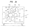
- Fig. 24 is a schematic block diagram showing the structure of a conventional polychromatic copying apparatus.
- a manuscript table 102 is mounted on the upper surface of the main body 101, and a scan unit 103 is provided below this manuscript table 102.
- the scan unit 103 consists of lamp 104, first and second mirrors 105, 106 a filter lens unit 107, third and fourth mirrors 108, 109 and so forth, and the lamp 104 and the first mirror 105 are integrated in a body so as to be movable in the directions A and B shown in the drawing.
- the second mirror 106 is constructed so as to move, according to the movement of the lamp 104 and the first mirror 105, at 1/2 of the speed of the movement.
- the blank form fed from a blank form cassette 114 is wound round a transfer drum 115 which rotates counterclockwise and is conveyed in between the photosensitive drum 111 and a transfer drum 115.
- the above mentioned yellow toner image is transferred onto the blank form on the transfer drum 115.
- the surface of the photosensitive drum 111 is cleaned in consecutive order by means of a cleaning unit 116 from the portion where the transfer has been completed.
- the filter lens unit 107 is changed over in the next place so as to transmit any color other than magenta color, and a developing part 117 for magenta color is selected at the same time, followed by a similar transfer operation as described above. Thereafter, the filter lens unit 107 is changed over so as to transmit any color other than cyanogen color, and a developing part 118 for cyanogen color is selected at the same time, thus performing a similar transfer operation as described above. Then, when the transfer of three primary colors has been completed, a composite image in yellow, magenta and cyanogen colors is formed on the surface of the blank form on the transfer drum 115.
- the blank form on the transfer drum 115 is conveyed to a fixing unit 122 with a belt 121, and the color image formed on the blank form surface by means of this fixing unit 122 is securely fixed onto the blank form. Then, the blank form completed with fixing is ejected to a tray 123, thus completing a series of color copying operation.
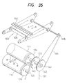
- Fig. 25 is a perspective view showing the outline of a position control mechanism of each movable part in the copying machine described above.
- the reference numeral 131 shown in the drawing is a chain with which the driving force of a motor (not shown) is transmitted, and which is engaged with a sprocket 133.
- 132 denotes a shaft on which the sprocket 133 and a gear 134 are mounted with a common shaft center
- 135 denotes a shaft on which the transfer drum 115 and a gear 136 are mounted.
- a pulley 142 is supported by the shaft through a bearing 141, and a movable pawl (not shown) which is driven by a solenoid, etc. is provided on the side of the pulley 142.
- a movable pawl (not shown) which is driven by a solenoid, etc. is provided on the side of the pulley 142.
- the rotation of the pulley 142 is conveyed to a pulley 148 through a wire 144, and the rotation of this pulley 148 is conveyed to the scan unit 103 through shaft, pulley and wire, etc.
- the lamp 104, etc. are moved in the direction shown with the arrow mark A corresponding to the rotation of the photosensitive drum 111.
- the driving pawl slips off the pin 143, the lamp 104, etc. are returned in the direction shown with the arrow mark B by means of the energizing force of a spring not shown.
- the scan unit 103 and the photosensitive drum 111 are mechanically interlocked with each other, the position of the electrostatic latent image formed on the photosensitive drum 111 becomes fixed. Moreover, since the photosensitive drum 111 and the transfer drum 115 rotate synchronously and in reverse directions with each other, and the position of winding the blank form round the transfer drum 115 is fixed, positions of images in each color transferred on the blank form are coincide with one another. As a result, color copying by process color printing is performed usually without causing any color shear.
- JP-A-60-218673 discloses a copying apparatus having three individual motors for driving the scanning mechanism, the photosensitive drum and the transfer drum. The position of each motor axis is input to a control circuit.
- driving motors are provided for the scan part provided movably on a predetermined straight line track, the photosensitive drum which rotates keeping a predetermined relationship with the movement of this scan part, and the transfer drum which rotates keeping a predetermined relationship with this photosensitive drum, respectively, and wherein the structure is constituted in such a way that said photosensitive drum and said transfer drum are driven individually by means of above mentioned driving motors, and pulse encoders are provided for detecting the rotational quantity of each of the above mentioned driving motors so as to control each of said driving motors individually based on the output of this pulse encoder.
- the optical scanning mechanism is returned to the stop position by means of energizing force of a spring, but some of these are constructed in such a way that a counter which outputs the present position signal of the optical scanning mechanism by means of an up-count and down-count of a rotation pulse synchronizing with the moving speed of the optical scanning mechanism is provided, and the optical scanning mechanism is made to move to the operation terminating position by the actual position signal corresponding to the output of said counter, and it is returned to the stop position thereof thereafter.
- an acceleration/deceleration control of the rotation of the transfer drum is performed so that the points of the transfer paper and the electrostatic latent image forming initiation point coincide with each other by performing the acceleration/deceleration control of the transfer drum. Therefore, if something abnormal happens in a rotary encoder employed for the purpose of controlling the grip timing of the transfer paper, the transfer initiation point and the latent image forming initiation point slip off and the positional relationship with the manuscript picture image is dislocated.
- the electrostatic latent images are formed three times in total in a polychromatic copying apparatus, the copied picture image which is faithful to the manuscript picture image is not available because of color shear.
- the motor which is the power source for the photosensitive subject is controlled under an acceleration condition even when the end timing of the transfer cycle is reached, and troubles such as burning of motor windings or driving circuits thereof are generated, making the maintenance operation very difficult thereafter.
- the movable optical system which scans the manuscript picture image, the photosensitive substance and the transfer drum are driven independently by means of individual servo loop, respectively.
- the transfer drum there are provided a rotary encoder which generates a pulse signal synchronizing with the rotation of the transfer drum, and a preset counter which rotates the transfer drum in accordance with the difference between a pulse train corresponding to the target value of the rotation quantity of the transfer drum and said pulse signal are provided in the servo loop, thereby to rotate the transfer drum until the count value of the preset counter becomes zero.
- a gripper for gripping the transfer paper is mounted on the circumferential surface of the transfer drum, and besides, a release cam which peels off the transfer paper transfer of which has been completed is arranged as it were seeing the circumferential surface. Therefore, if the gripper and the release cam bite each other, or the gripper engages other protruded part of the frame for some causes, the rotation of the transfer drum presents a locked condition. Then, since the pulse signal which is synchronous with the rotation will no longer be output, there have been such problems that the counter value of the present counter is not reduced at all, the applied voltage of the motor which is the motive power source of the transfer drum continues to be under an accelerated condition, and troubles such as burning of windings and driving circuits thereof are caused.
- the photosensitive substance is started in such a way that the time is measured with the start initiation timing of the optical scanning mechanism as the initiation point, and the electrostatic latent image in the next color is formed by starting the optical scanning mechanism again when the measured time reaches the copy initiation time for that next color.
- the synchronous relationship between the optical scanning mechanism and the photosensitive substance is dislocated in every copy cycle for respective colors by means of nonuniformity of the rotation period of the photosensitive substance, and such a dislocation is accumulated and causes even bigger non-uniformity in shade for each color.
- the acceleration/deceleration control of the transfer drum 6 is performed so that the transfer initiation point and the latent image forming initiation point may coincide with each other with the grip timing signal of the transfer paper which is output synchronously with the rotation of said drum as the reference.
- a plastic net is formed in the length corresponding to the maximum length of the transfer paper so as to attract the transfer paper with static electricity.
- the control for returning the optical scanning mechanism for stopping the position thereof has heretofore been depending only on the energizing force of a spring. Therefore, the stop position of the optical scanning mechanism is shifted in every copy cycle due to the state variation of a motive power conveying mechanism, etc., which makes the running time of the optical scanning mechanism different when copying is initiated again.
- the positional relationship between the manuscript picture image and the copied picture image or the positional relationship between the respective colors do no longer coincide with each other, causing such problems that color shear is produced in a polychromatic copying machine and the picture quality is deteriorated.
- the rotation of the photosensitive substance, the transfer drum and so forth are controlled based on the pulse signals from a pulse generator (a rotary encoder) mounted on the rotation shaft of each rotating body.
- An object of the present apparatus is to allow a more accurate synchronization.
- the invention accordingly provides a copying apparatus comprising
- the copying apparatus produces a copied picture image faithful to the manuscript. No color shear nor positional dislocation occurs.
- a sensor is provided for generating a signal corresponding to a predetermined position of the scanning means.
- a sensor is provided for generating a signal corresponding to the position of means holding the recording sheet on the transfer means.
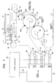
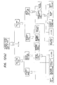
- Fig. 1 is a general block diagram of a trichromatic separation type polychromatic copying machine.
- the reference numeral 1 denotes a drum type electronic photosensitive substance (hereinafter referred to as a photosensitive drum) which is driven at a circumferential speed V in the direction shown with an arrow mark with the shaft 2 as the center.
- Reference numeral 3 denotes a charger for giving photosensitivity to the photosensitive drum 1.
- Reference numeral 4 denotes an exposure part, and 5Y, 5M and 5C are color toner developing units corresponding to separate colors, i.e. units for yellow, magenta and cyanogen colors, respectively, in the case of this embodiment.
- Reference numeral 6 denotes a transfer drum and reference numeral 7 denotes a photosensitive drum cleaner.
- Reference numeral 8 denotes a manuscript placing table, on which a manuscript G is placed with the picture image surface thereof facing downward.
- Reference numeral 9 denotes a manuscript scanning optical system exposing the photosensitive drum 1, and this system consists of a first movable mirror 11 which reciprocates from the left to the right of the table along the bottom thereof at the same speed as the circumferential speed V of the photosensitive drum 1 together with a manuscript illuminator 10 under the manuscript placing table 8 and which scans the manuscript surface facing downward placed on the table 8 through the table 8, a second and a third mirrors 12, 13 which reciprocate at the speed of 1/2 of the circumferential speed of the photosensitive drum 1, and a fixed mirror 14.
- the movable optical system 10, 11 reciprocates and the manuscript picture image is scanned from the left to the right in successive order through the table 8.
- the scanning light L is transmitted through the path of the first mirror 11 ⁇ the second mirror 12 ⁇ the third mirror 13 ⁇ the fourth mirror 14, and image-formation is made by means of an exposure part 4 on the surface of the photosensitive drum in the rotating state.
- Reference numeral 15 designates a color separation filter unit, wherein 4 pieces of filters, a blue ray transmission filter 15B, a green ray transmission filter 15G, a red ray transmission filter 15R and a neutral filter 15N are mounted radially at the interval of 90° on the rotating shaft of the filter unit 15. By rotating the rotation shaft by 90° at a time, every filter is positioned in the light path of the scanning light L. Furthermore, this filter unit 15 and respective color developing units 5Y, 5M and 5C are associated.
- the yellow toner developing unit 5Y is operated when the blue filter 15B is located at the switched position in the light path of the scanning light L
- the magenta toner development unit 5M is operated when the green filter 15G is at that position
- the cyanogen toner developing unit 5C is operated when the red filter 15R is at that position.
- the transfer drum 6 is rotated in the direction shown with an arrow mark with the shaft 16 as the center at the same circumferential speed as the photosensitive drum 1, and the transfer paper fed from a paper feeding part (not shown) to the drum 6 is held by a gripper 17 and it is rotated together with the drum 6 under wound state round the circumferential surface of the drum 6.
- the picture image forming process is initiated for the first color separated image by means of the print start button, but the picture image forming process is initiated for the second and the third colors by means of generation of a print restart signal inside the circuit when the previous process is completed.
- the blue filter 15B intervenes in the exposure light path when the picture image is formed for the first time, and the blue color component image of the manuscript image is formed on the photosensitive drum surface as a yellow toner image which has the complementary color relationship with the blue color by the action of the yellow toner developing unit 5Y, and the yellow toner image is transferred onto the transfer paper surface wound round the circumferential surface of the transfer drum 6.
- the green filter 15G intervenes in the exposure light path, and the green color component image of the manuscript image is formed on the surface of the photosensitive drum as a magenta toner image which has the complementary color relationship with the green color by the action of the magenta toner developing unit 5M, and this magenta toner image is further transferred with superposition on the transfer paper surface on which transfer process of the yellow toner image has already been made and which is still in the wound state around the drum 6.
- the red filter 15R intervenes in the exposure light path, and the red color component image of the manuscript image is formed on the surface of the drum 1 as a cyanogen toner image which has the complementary color relationship with the red color by the action of the cyanogen toner developing unit 5C, and this cyanogen toner image is transferred with superposition on the transfer paper surface on which the yellow toner image and the magenta toner image have already been transferred as described above.
- a polychromatic image which is same as the manuscript image is formed by composition on the transfer paper surface by means of transfer with superposition of abovementioned respective color toners. Then, after the above stated repeated transfer process has been completed, the transfer paper held on the drum 6 is separated from the drum 6, and it is fed to a fixing unit (not shown) by a conveyor unit (not shown) so as to be subject to the fixing process, and ejected from a paper ejecting tray as a polychromatic print.
- the movable optical system, the photosensitive drum 1, and the transfer drum 6 are moved or energized for rotation by means of independent motors, respectively.
- the power source for the movable optical system 10, 11 is provided by a motor 18 (hereinafter referred to as a CRG motor 18) through a pulley 19 and a wire 20.
- the power sources for the photosensitive drum 1 and the transfer drum 6 are provided by a motor 21 (hereinafter referred to as the PR motor 21) and a motor 22 (hereinafter referred to as the TR motor 22), respectively.
- the CRG motor 18, PR motor 21 and TR motor 22 are controlled by means of a servo controller 23.
- the servo controller is further controlled by a master controller 24 as a host control means.
- the master controller 24 receives an IMS signal and a PRZ signal, etc. which will be described later from the servo controller 23, and it executes the control, abnormality diagnosis processing and so forth of the whole copying cycle. Besides, the servo controller 23 and the master controller 24 are coupled by a serial data line 25 other than above mentioned respective signal lines.
- pulse generators 26, 27 and 28 are provided on each of the rotation shafts of the CRG motor 18, the PR motor 21 and the TR motor 22 for generating pulse signals which synchronize the rotation of each motor, respectively.
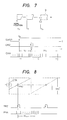
- a pulse generator 26 consisting of a rotary encoder 26A for generating a rotation pulse signal CRZ which shows one rotation of said motor 18, a rotary encoder 26B which generates one pulse signal CRB for any predetermined rotation angle of the CRG motor 18, and a rotary encoder 26C which generates a pulse signal CRA having a phase angle which is 90 degrees different from above mentioned signal CRB is mounted as is shown in detail in Fig. 2.
- a pulse generator 27 consisting of a rotary encoder 27A for generating a rotation pulse signal PRZ which shows one rotation of the photosensitive drum 1, a rotary encoder 27B which generates one pulse signal PRB for every predetermined rotation angle of the PR motor 21, and a rotary encoder 27C which generates a pulse signal PRA having a phase angle 90 degrees different from above mentioned signal PRB is mounted as is shown in detail in Fig. 3.
- PRO of the photosensitive drum 1 shown in Fig. 3 is the rotation initiation point of said drum 1
- the encoder 27A is mounted in such a way that the signal PRZ is generated at a rotation timing approximately corresponding to the rotation initiation point PRO.
- IMO is a forming initiation point of the electrostatic latent image and is located at the position shifted from PRO by ⁇ degrees.
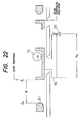
- a pulse generator 28 consisting of a rotary encoder 28A which outputs one pulse signal TRZ per rotation of said motor 22 (provided, 6 pulse signals per rotation of the transfer drum 6 due to a decelerating mechanism located between the TR motor 22 and the transfer drum 6) at an equal interval, a rotary encoder 28B which generates one pulse signal TRB for every predetermined rotation angle of the TR motor 22, and a rotary encoder 28C which generates a pulse signal TRB having a phase 90 degrees different from that of above mentioned signal TRB is mounted as shown in details in Fig. 4.
- a protruded actuator 6A is provided at a position corresponding to the position of the gripper 17 on the internal circumferential surface of the transfer drum 6 which is driven by the TR motor 22, which actuates the sensor 6B fixed to the frame, thereby to take out the grip timing signal TRS of the transfer paper.
- the pulse generator consisting of the actuator 6A and the sensor 6B is referred to as the TR sensor 60.
- the servo controller 23 predicts the grip timing of the transfer paper by counting the output signals of the encoder 28B or 28C with the output signal TRS of the TR sensor 60 as the reference, and further calculates the time (distance or position) required for the grip position at the predicted timing to practically reach the transfer initiation point PO, and it accelerates or decelerates the speed of the TR motor 22 so that the latent image forming initiation point IMO and the transfer initiation point PO may coincide with each other.
- a switch 29 provided at a location apart from the home position of the movable optical system 10, 11 at a predetermined distance in the operating direction is employed for the purpose of detecting the scan initiation timing of the picture image, and the operation timing of this switch (hereinafter referred to as the REG sensor) 29 is employed as the scan initiation timing.
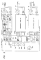
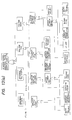
- Fig. 5 is a block diagram showing the detailed constitution of the servo controller 23. Roughly dividing, the servo controller 23 consists of three systems of synchronous servo circuits 30, 31 and 32 which control the rotation status of the CRG motor 18, the PR motor 21 and the TR motor 22 independently from the target rotation status, and a control circuit 33 which controls above-mentioned synchronous servo circuits in a predetermined synchronous relationship.
- the synchronous servo circuit 30 consists of a direction discriminator 300, OR-gates 301 and 302, an FV converter 303, a synchronous compensator 304, an FV converter 305, an error amplifier 306, a direction discriminator 307, an overcurrent detector 308 and a PWM chopper 309.
- a speed command pulse SCP composed of signals in phase A and phase B having a 90 degree phase difference which are output from a speed command generator 330 of the control circuit 33
- a position pulse PCP composed of UP signal and DOWN signal which are output from a position command generator 331 of the control circuit 33
- a gate off pulse GOFF which cuts off the output gate of the PWM chopper 309.
- the overcurrent detection signal of the overcurrent detector 309 and the direction of rotation detection signals RPU and RPD which show whether the direction of rotation of the CRG motor 18 detected with the direction discriminator 307 is in the normal direction of rotation (UP) or in the reverse direction of rotation (DOWN) are output to the control circuit side.
- the output signal CRZ of the pulse generator 26A is output to the side of the control circuit 33 as it is.
- These signals RPU, RPD and CRZ are input to the optical system position detector 332, thereby to detect the picture image scan position of the movable optical system 10, 11.
- the overcurrent detection signal OC is input as the interrupt signal of a microprocessor (CPU) 334 through an OR-gate 333 of the control circuit 33, and when an overcurrent flows in the CRG motor 18, an emergency shutdown of the CRG motor 18 is executed by the interrupt processing of the CPU 334.
- the overcurrent detection signals for the PR motor 21 and the TR motor 22 are input to the OR-gate 333 likewise.
- the PR motor 21 no position control is performed, but only the speed control is performed. Therefore, the position control pulse is not input to the synchronous servo circuit 31, but only the speed command SCP(P) is input from the speed command generator.
- the TR motor 22 since it is necessary to perform an acceleration/deceleration control of the TR motor 22 so as to have the transfer initiation point coincide with the latent image forming initiation point, the speed command pulse SCP(T) and the position command pulse PCP(T) are input from the acceleration/deceleration command generator 336.
- the direction of the rotation detection signals RPU, PPD and the output signals TRZ of the pulse generator 28A are input to a transfer drum rotation angle detector 337, and the present rotation angle of the TR drum 6 is detected by these signals.
- Constitution is made in such a way that the CPU 334 has the generator 336 generate the acceleration/deceleration command pulse by means of the rotation angle detection signal so that the transfer initiation point and the latent image forming initiation point may coincide with each other.
- the basic operation of the control circuit 33 is controlled by the CPU 334, but the CPU 334 executes the control operation based on control programs or control parameters that are stored in ROMs 345, 346 or RAM 347.
- the console panel on which switches for setting well-known copy modes such a number of copy sheets, the blank form size and the reduction/enlargement ratio, and a copy start switch, an abnormality display lamp, and a switch for setting a command for diagnosis for the purpose of maintenance and inspection are provided, is connected to the master controller 24. Therefore, this various switch information is sent to and received from the master controller 24 through a serial data I/O port 338.
- the direction discriminator 300 discriminates the direction of the rotation command through the instrumentality of the phase difference between the phase A and the phase B of said pulse SCP(C), and it generates a command pulse SPA corresponding to the command direction described above.
- the direction discriminator 300 outputs SPA which has a period corresponding to the target speed commanded by the speed command pulse, and in case of the direction of reverse rotation, the direction discriminator outputs SPB which has a period corresponding to said target speed.
- the signal SPA is input to a synchronous compensator 304 through an OR-gate 301 and also to an FV converter 303 at the same time.
- the signal SPB is input to the synchronous compensator 304 through an OR-gate 302 and also to the FV converter 303 at the same time.
- the FV converter 303 converts the signal into a voltage signal corresponding to the period thereof, and it inputs said voltage signal to an error amplifier 306 as the speed command.
- the synchronous compensator 304 is constituted in such a way that it converts the count value of the up-down counter into an analog signal, performs a non-linear conversion of said signal by employing a route amplifier thereafter, and it inputs said analog signal to the error amplifier 306 as a synchronous error signal.
- the output signal of the OR-gate 301 is applied to the input of the up-count input of the above-mentioned up-down counter, and the output signal of the OR-gate 302 is applied to the input of the down-count input thereof.
- the direction discriminator 307 corresponds to the present direction of rotation of the CRG motor 18 depending on lead-lag of phases of these signals CRA, CRB, and it outputs a pulse signal RPU or RPD having a period which is in proportion to the rotation speed.
- This signal RPU or RPD is input to the FV converter 305 and converted into a voltage signal corresponding to the period thereof, and it is input to the error amplifier 306 thereafter as a speed feedback signal.
- the deviation between the voltage signal of the speed command and the speed feedback signal is detected by the error amplifier 306, thereby to control the output current of the PWM chopper 309 so that said deviation becomes zero.
- the output signal RPU of the direction discriminator 307 is input to the OR-gate 302, and the output signal RPD is input to the OR-gate 301.
- the signal RPU becomes to be input to the down-count input of the synchronous compensator 304.
- the signal RPD becomes to be input to the upcount input.
- the count value accordingly becomes smaller in the synchronous compensator 304 as the CRG motor 18 rotates, but the analog conversion voltage of the count value thereof is input to the error amplifier 306 as a synchronous error signal.
- the output current of the PWM chopper 309 is also varied by said synchronous error signal.
- the CRG motor 18 will rotate in a phase synchronizing with the speed command pulse SPC(C) and at a speed corresponding to the command speed.
- phase command pulse PCP(C) when the phase command pulse PCP(C) is input, an error voltage which corresponds to the deviation between the phase of said pulse PCP(C) and the phase of the output pulse RPU or RPD of the direction discriminator 307 is output from the synchronous compensator 304, and the position of the movable optical system is controlled to be set at the target position by varying the output current to the CRG motor 18 so that said error voltage becomes zero.
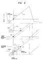
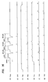
- Fig. 6 is a time chart showing respective rotation angles ⁇ CRG , ⁇ PR and ⁇ TR of the CRG motor 18, the PR motor 21 and the TR motor 22 and synchronous relationship thereof, and the X-axis and the Y-axis represent time and rotation angle, respectively.
- the CRG motor 18 is started after the time t. Then, when the movable optical system reaches the position of the REG sensor 29 and the scan initiation timing signal SNSR is output from said sensor 29, electrostatic latent images are formed in consecutive order starting from the electrostatic latent image forming initiation position position IMO of the photosensitive drum 1 prescribed by the generation timing of said timing signal SNSR. On the other hand, the TR motor 22 which is the power source of the transfer drum 6 is started almost simultaneously with the PR motor 21.
- the time required for the grip timing signal TRS of the transfer paper to be generated is and calculated with forecast, and if the rotation speed V PR of the transfer drum 6 is at such a speed that the latent image forming initiation point IMO and the transfer point PO coincide with each other judging from the forecast value, the TR motor 22 is accelerated under the accelerating state as is shown with the variable-speed line i.
- control is commenced so as to reduce the speed of the motor 22 after the time tp for the purpose of having the grip timing coincide with the normal timing.
- the acceleration control of the TR motor 22 is initiated after the time tp so as to have the grip timing coincide with the normal timing.
- Such an acceleration/deceleration control is performed by varying the period of the acceleration/deceleration command pulse which is output from an acceleration/deceleration command generator 336 shown in Fig. 5.
- the latent image forming initiation point IMO and the transfer initiation point coincide with each other, thereby to form by transfer of a picture image having no color shear.
- the polychromatic copying such a process is repeated three times, thereby to form a polychromatic print.
- control The contents of control will hereinafter be described by control items in detail.
- the motive power to move the movable optical system is conveyed through wires and pulleys. Accordingly, when the movable optical system is returned to the stop position (starting position when copying is initiated), the stop position of the movable optical system is shifted in every copying cycle due to the status change of the motive power transmission mechanism and so forth, the running distance of the movable optical system becomes different when copying initiation is started again, and the position relationship between the manuscript picture image and the copied picture image, or the position relationship between respective colors does not coincide, which appears as a color shear in the polychromatic copying apparatus. Accordingly, it is required to control the stop position of the movable optical system always at the normal stop position in order to prevent such a color shear from occurring.
- measuring means for measuring the time required from the operation timing of the REG sensor 29 to the stop of the movable optical system by counting the rotation pulse signal CRB or CRA are provided inside the servo controller 23 in the embodiment shown in Fig. 1.
- the abovesaid arrangement is incorporated in the control program of the CPU 334.
- measurement by employing said measuring means is executed at every predetermined time such as immediately before the copying initiation of the first copy or immediately before shifting to a series of copying cycles.
- the movable optical system 10, 11 is moved in the direction of scanning the manuscript picture image at either time described above, and the measurement is made as shown in Fig. 7, with the generation timing of the output signal SNSR of the REG sensor 29 which was operated when said optical system was returned to the stop position thereof as the reference, on the time ND required from said reference timing for the generation timing of the reference signal CRZ.
- the starting position of the optical system 10, 11 always remains at the same position, thus eliminating a position dislocation or color shear in the copied picture image.
- a plastic net 61 for the purpose of attracting the transfer paper by static electricity is formed in the length corresponding to the maximum length of the transfer paper as shown in Fig. 4.
- abnormal transfer viz., so-called deletion is generated at the time of transfer. Therefore, it is required to perform a control to stop the PR motor 21 and the TR motor 22 so that the electrostatic latent image forming area of the photosensitive drum 1 and the plastic net do not coincide with each other. Besides, such a relationship must also be returned to the normal position relationship when the relationship between both has been shifted due to paper jam.
- the starting position relationship of both motors is controlled in this embodiment by starting the PR motor 21 and the TR motor 22 before and at the time of completion of a series of copying cycles, by counting the signal PRA (or PRB) and the signal TRA (or TRB) with the signals PRZ and TRS as the reference, respectively, and by stopping the PR motor 21 and the TR motor 22 when such a positional relationship that the electrostatic latent image forming area and the plastic net 61 are not overlapped is obtained.
- the signal PRA (or PRB) is counted with the signal PRZ as the reference and the PR motor 21 is stopped when the count value reaches a predetermined value N STP
- the TR motor 22 as shown in the time chart of Fig. 9, the signal TRA (or TRB) is counted from the generation timing of the signal TRZ which appears in the first place after rising of the signal TRS, and control is performed so as to stop the TR motor 22, after a count value N PO has been reached where the gripper 17 passes the transfer point PO.
- the PR motor 21 is reached.
- the photosensitive drum 1 and the transfer drum 6 are controlled in such a positional relationship where the electrostatic latent image forming area and the portion of plastic net 61 are not overlapped. And, this position control is performed immediately before or at the time of completion of a series of copying cycles.
- the time is measured with the start initiation timing of the movable optical system as the starting point, and the movable optical system has been activated again when the measured time reaches the copying initiation time for the next color so as to start the photosensitive drum 1 thereby to form the electrostatic latent image in the next color.
- a counter for counting the signal PRA or PRB with the signal PRZ as the reference angle is provided inside the servo controller 23 so that the movable optical system is activated whenever the rotation angle ⁇ B of the photosensitive drum 1 shown with the count value of said counter reaches a fixed rotation angle L1 as shown in the time chart of Fig. 10.
- acceleration/deceleration control of the transfer drum 6 is performed so that the transfer initiation point PO and the latent image forming initiation point IMO coincide with each other with the signal TRS, 6 pcs. of which are output per rotation of said drum 6 and the output signal SNSR of the REG sensor 29 as the reference, but the accuracy of the TR sensor 60 which generates the signal TRS is low, and a 1:6 gear is interposed between the TR motor 22 and the transfer drum 6.
- the transfer initiation point PO and the latent image forming initiation point IMO slip off each other even when only one tooth of the gear is dislocated.
- the signal TRA or TRB is counted with the signal TRZ, which appears in the first place after the signal TRS is generated, as the reference, and it is judged that the time when the count value reaches the value corresponding to the normal transfer point PO is the transfer point PO, thus controlling the transfer initiation position.
- the transfer paper It is required for the transfer paper to be held and conveyed by the gripper 17 of the transfer drum 6 so that the point position of the transfer paper coincide with the transfer initiation point IMO at the transfer initiation point PO. Accordingly, it is required to detect the present position of the gripper 17 when scanning of the picture image is commenced, and to perform an acceleration/deceleration control of the rotation speed of the transfer drum 6 so that the detected position coincides with the latent image forming initiation point IMO at the transfer point PO.
- a positional error of the gripper 17 has been detected in the scan initiation timing for the picture image, and the acceleration/deceleration control of the transfer drum has immediately been executed based on said positional error.
- the rotation speed of the transfer drum 6 is varied immediately before the grip operation on the transfer paper, there has been such a problem that misgripping may occur.
- the acceleration/deceleration control is executed starting at the time tp after the time when the grip operation is practically completed so as to complete the control before the transfer point PO is reached. This is actualized by providing a soft timer for measuring the time tp inside the servo controller 23.
- the photosensitive drum 1, the transfer drum 6 and the movable optical system are controlled by independent motors and the servo loops thereof, respectively, in the present embodiment as described previously, a position control for positioning respective relationship at normal positions before initiating the copying cycle is required.
- a position control is executed based on the pulse signals (PRZ, TRZ, etc.) which synchronize with the rotation of each motor. Accordingly, when an abnormal matter occurs in these pulse signals or signal paths thereof, the positioning does not only become impossible, but such a situation will be brought about that the motor remains in an accelerating condition even after passing the specified position, which may cause serious troubles such as burning of motor windings and driving circuits thereof.
- the time te required until the PR motor 21 and the TR motor 22 come to a stop is measured based on the clock signal having a predetermined frequency with the signal PRZ which is generated in the timing t1 just before the CRG motor 18 switches to the direction of rotation having the movable optical system return to the home position thereof as the time measurement initiation point. If the time te is, for instance, at 17.2 seconds or longer, it is judged that something abnormal has happened in signals PRZ, PRA, TRZ, TRA, etc., thereby to stop these motors 21, 22 compulsorily and also to stop the copying operation thereafter.
- Such abnormality detection processing is performed whenever a series of copying cycles are completed.
- the signal PRZ is important in setting the latent image forming initiation point IMO accurately. Therefore, as shown in Fig. 15, the length T B of a period of the signal PRZ is measured based on the clock signal having a predetermined frequency after the PR motor 21 has been started, and the length T B is judged abnormal if it does not fall within the range between the upper limit value and the lower limit value, thereby stopping the copying operation thereafter.
- the origin position setting control for the photosensitive drum 1 and the transfer drum 6 is performed in advance immediately before the copying cycle in three colors.
- the signal PRZ which appears in the first place in case of the origin position setting control is found by measuring the time from the start timing of the PR motor 21 to have a shorter period than that of the signal PRZ which appears later. Accordingly, judgement is made that this first signal PRZ is abnormal only, when the period thereof exceeds the upper limit value.
- Fig. 17(a) the processing of the CPU 334 which detects an abnormal period of said signal PRZ is shown with a flow chart.
- the "Mode 0" in the first step shows a mode when the speed of the PR motor 21 is zero as shown in Fig. 17(b).
- the processing shown in the flow chart is executed only for "Mode 1" when the PR motor 21 is under rotating condition, and a gate-off signal of the PWM chopper in the synchronous servo circuit 31 is generated if the relationship, the lower limit value ⁇ T B ⁇ the upper limit value is not maintained, thereby to stop the rotation off the PR motor 21 immediately and to transmit the information indicating that something abnormal has occurred in the signal PRZ to the master controller 24.
- Signals TRS and TRZ are important in setting the latent image forming initiation point IMO to the transfer point PO accurately. Abnormality in these signals is caused by abnormality in the encoder and under-and-over voltage of the motor.
- the time interval TC1 between the signal TRS which once rises and falls and the signal TRZ which appears in the first place immediately after the signal TRS falls is measured based on the clock signal having a predetermined frequency. If the time interval TC1 is out of the range between the upper limit value and the lower limit value, it is judged that the synchronous relationship between the signal TRS and the signal TRZ is not in a normal condition, and the copying operation is stopped thereafter.
- the time interval TC2 from the signal TRZ to the new signal TRS which appears after TC1 is measured based on abovementioned clock signal, and judgement is made that it is abnormal if the time interval TC2 does not fall within the range between the upper limit value and the lower limit value.
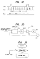
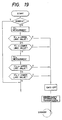
- Fig. 19 the processing of the CPU 334 for detecting such an abnormal condition is shown with a flow chart.
- “Mode 0" at the first step shows that the speed of the TR motor 22 is zero.
- the processing of this flow chart is executed only in "Mode 1" when the TR motor 22 is under rotating condition, and when TC1 and TC2 are abnormal, the gate-off signal of the PWM chopper in the synchronous servo circuit 32 is generated, thereby to stop the rotation of the TR motor 22 immediately and to transmit the information indicating abnormal synchronization between signals TRS and TRZ to the master controller 24.
- Acceleration/deceleration control is performed on abovementioned CRG motor, PR motor 21, and TR motor 22 by adjusting the motor current with a synchronous compensator 230 such as shown in Fig. 20 provided in the servo controller 23.
- a synchronous compensator 230 such as shown in Fig. 20 provided in the servo controller 23.
- an up-down counter 231 up-counts this command pulse train. If the count value of the counter 231 is increased, the output voltage of a DA converter which converts the count value of said counter 231 into an analog voltage is also increased. Since the output voltage of the DA converter 232 is applied to, for example, the TR motor 22 through an amplifier 233, the TR motor 22 is started and accelerated in consecutive order.
- the signal TRA (TRB) is generated from a pulse generator 28 which is coupled to the rotation shaft thereof. Since this signal TRA is input to the down-count input of the down-counter 231, the count value of the counter 231 becomes zero when the rotation quantity of the TR motor 22 reaches the rotation quantity corresponding to the command pulse train, thereby to stop the TR motor 22.
- the rotation of each motor is made to reach the target value by means of such a synchronous compensator, but a gripper 17 for gripping the transfer paper is mounted on the circumferential surface of the transfer drum 6, and a release cam (not shown) for releasing the transfer paper completed with transference is also provided, as it were, seeing the circumferential surface. Accordingly, when the gripper 17 and the release cam bite each other for some reason, or the gripper 17 bites another protruding portion of the frame, the rotation of the TR motor 22 is brought into a locked condition. Thus, since the signal TRA or TRB is not output, the count value of the up-down counter 231 is no longer reduced at all, and the voltage applied to the TR motor 22 continues the acceleration condition, thus causing troubles such as burning of windings and driving circuits thereof.
- measuring means for measuring the distance to the stop position of the movable optical system by counting pulse signals CRA and CRB after the REG sensor 29 has been operated are provided in the CPU 334 of the control circuit 33.
- measuring means are different in the phase by 90 degrees from that of pulse signals CRA and CRB, the moving direction is discriminated depending on which phase is leading. If the optical system is moving toward the stop position, the distance to the stop position is measured by counting pulse signals CRA or CRB with the operating timing of the REG sensor 29 as the starting point of measurement. Then, the measured value is stored until the next measuring time.
- the CPU 334 reads the measured value of measuring means when the power supply of the relevant copying machine is connected, immediately before copying initiation for the first sheet, or immediately before shifting to a series of copying cycles, and it compares the measured value with a predetermined value.
- the CPU 334 reads the measured value ⁇ i of measuring means immediately before a series of copying cycles and so forth, and it compares to find whether the absolute value of the difference from the position ⁇ S of the stopper 91
- Such a measurement is executed every predetermined time such as when the power supply of the relevant copying machine is connected, immediately before the initiation of copying of the first sheet or immediately before shifting to a series of copying cycles.
- the above mentioned positioning control and abnormality processing are executed by means of the servo controller 23.
- the diagnosis becomes difficult when something abnormal occurs in any of the servo loops for 3 sets of motors in total. Therefore, it is arranged in the present embodiment in such a way that the diagnosis mode and the copying mode are provided in the master controller 24, and by selecting the diagnosis mode giving a command for diagnosis, the servo controller 23 is made to execute the operation corresponding to said command for diagnosis, thereby to enable diagnosis of the results.
- Fig. 23 is a state transition drawing showing the transition of the operation state in the present embodiment. The right side thereof shows the state transition in the copy mode and the left side thereof shows the state transition in the diagnosis mode both after the initializing state.
- the state is under preparation state until completion of preparation such that the temperature of the fixing unit reaches a predetermined temperature, but, when the preparation state is over, cleaning of the photosensitive drum and system initializaing are performed. Thereafter, the state of every servo loop is read by the master controller 24 through the serial data line 25.
- the system ready state is created and copying cycles by every color are performed in consecutive order by means of input of the copy start command.
- the cycle comes to the end and returns to the system ready state.
- the abnormality stop state is produced by means of abnormality detection signal generated for the above.
- the unit in the stand-by-state waiting for the diagnosis command.
- the diagnosis command for positioning the CRG motor 18, the PR motor 21, the TR motor 22 and the movable optical system is input, the positioning operation is performed based on the diagnosis command which is input.
- a diagnosis command for the pulse generator such as a rotary encoder or the sensor is input, the relevant motor is made to rotate, and the servo controller 23 is made to perform diagnosis on correctness or incorrectness of the signal of the pulse generator, etc. which is coupled to the motor, and to transmit the information on the result of diagnosis to the master controller 24.
- the PR drum 1 and the TR drum 6 are rotated, rising and trailing timings of output signals SNSR and PRZ of the REG sensor 29 and the output signal TRS of the TR sensor 60 are detected, and the detected information is transmitted to the master controller 24 at that time.
- diagnosis is made on the rotating state and positioning operation of the movable optical system
- the PR drum 1 and the TR drum 6 the positioning operation (P4 mode) is continued until the stop command or the emergency stop command is input from the console panel.
- the PR drum 1 and the TR drum 6 are also operated until the stop command or the emergency stop command is input from the console panel.
- copying with an enlargement ratio is feasible by adjusting the moving speed of the movable optical system to be relatively slower than the rotation speed of the photosensitive drum and the transfer drum, and in the reverse case, copying with a reduction ratio is possible.
- composition is made in such a way that there is provided measuring means for measuring the time interval of the reference signal generated synchronously with the rotation of the photosensitive substance, and the copying operation is stopped forcibly when the time interval measured by this measuring means is out of the specified range. Accordingly, it is possible to prevent troubles such as burning of a motor from occurring and to make the maintenance operation easy thereafter.
- switching means that is disposed at a predetermined distance from the stop position of the optical scanning mechanism toward the scanning direction of the manuscript picture image and is operated every time said optical scanning mechanism reciprocates for the purpose of scanning for reading the manuscript picture image
- reference signal generating means that is coupled with the rotation shaft of a motor for driving said optical scanning mechanism and generates a reference signal between the operating position of said switching means and said stop position
- pulse generating means that is coupled with the rotation shaft of the motor for driving said optical scanning mechanism, and generates pulses at every predetermined rotation angle
- measuring means for measuring the time interval from the operation timing of said switching means to the generation timing of said reference signal by counting said pulses
- control means for executing emergency shut down of the copying operation when a measured value of said measuring means does not fall within a predetermined range at the starting time of said optical scanning mechanism. Therefore, it is possible to prevent troubles such as burning of the motor for moving the movable optical system from occurring, and also to aim at the reduction of the maintenance cost.
- reference signal generating means for generating a reference signal which is employed as the reference for the transfer initiating position of an electrostatic latent image synchronously with the rotation of transfer means
- pulse generating means for generating a pulse signal which corresponds to the grip timing of a transfer paper synchronously with the rotation of abovesaid transfer means
- measuring means for measuring the synchronous relationship between said reference signal and said pulse signal and the time interval of said reference signal
- control means which discriminates whether measured synchronous relationship and time interval fall within the specified range or not, and when those are out of the specified range, stops the copying operation. Accordingly, it is possible to obtain a copied picture image which is faithful to the original picture image and to prevent troubles such as burning of motors from occurring.
- a switching means that is disposed at a predetermined distance from the stop position of the optical scanning mechanism toward the scanning direction of the manuscript picture image, and which is operated every time said optical scanning mechanism reciprocates for the purpose of scanning for reading the manuscript picture image
- reference signal generating means that is coupled with the rotation shaft of a motor for driving the optical scanning mechanism, and generates a reference signal between the operating position of said switching means and said stop position
- pulse generating means that is coupled with the rotation shaft of the motor for driving the optical scanning mechanism, and which generates pulses at every predetermined rotation angle
- measuring means for measuring the time interval from the operation timing of said switching means to the generation timing of said reference signal by counting said pulses
- control means for controlling the stop position of the optical scanning mechanism based on the measured value of said measuring means. Therefore, it is possible to obtain a good picture quality having neither color shear nor positional dislocation even if there is any state variation in the motive power conveying mechanism such as belt that moves the optical system.
- control means for controlling the positional relationship between the photosensitive substance and the transfer means with a predetermined relationship before initiation or after the termination of the copying cycle. Therefore, it is possible to keep the starting positional relationship between the photosensitive substance and the transfer drum always under normal relationship, thereby to prevent deletion from occurring at the time of transfer.
- pulse generating means for generating a pulse signal synchronizing with the rotation of the transfer means
- timing pulse generating means for generating timing pulses which represent the grip timing for a transfer paper synchronously with the rotation of said transfer means
- control means which counts said pulse signals after said timing signal is generated, and which controls the transfer operation by recognizing the time when the count value reaches a predetermined value as the reference point for the transfer initiation point.
- pulse generating means for generating a pulse signal having a predetermined frequency
- counting means for counting pulse signals generated by said pulse generating means from the picture image scanning termination point of said optical scanning mechanism
- control means for shutting down emergently the copying operation when said copying operation is not terminated when the counted value reaches a predetermined value.
- control means which stops the copying operation when an overflow output is generated from the counter means which rotates the transfer means in accordance with the difference between the pulse train corresponding to the target value of the rotation quantity of the transfer means and the pulse signal which synchronizes with the rotation.
- reference signal generating means for generating a reference signal which is used as the reference for the form ing initiation position of the electrostatic latent image synchronously with the rotation of the photosensitive substance, and control means for having the optical scanning mechanism start when the rotation angle of the photosensitive substance reaches a predetermined angle based on the reference signal generated from the reference signal generating means.
- control time of acceleration or deceleration by the transfer means is limited to the interval until the point of the transfer paper reaches the transfer point after the transfer paper is gripped. Accordingly, it is possible to perform acceleration/deceleration control of the transfer drum without causing misgripping.
- control means for controlling respective means such as transfer means
- a copy mode for controlling a series of copying processes by controlling abovementioned respective means and a diagnosis mode for making a diagnosis of abovementioned respective means. Therefore, it is possible to easily make a diagnosis of an abnormality existing in means for controlling each portion of a copying machine.
Landscapes
- Physics & Mathematics (AREA)
- General Physics & Mathematics (AREA)
- Engineering & Computer Science (AREA)
- Microelectronics & Electronic Packaging (AREA)
- Color Electrophotography (AREA)
- Control Or Security For Electrophotography (AREA)
Claims (7)
- Kopiermaschine, enthaltend
eine photosensitive Einrichtung (1), auf der mittels einer Abtasteinrichtung (9) ein elektrostatisches latentes Bild eines Originalbildes (G) gebildet wird;
eine Entwicklereinrichtung (5) zum Entwickeln des latenten Bildes;
eine Übertragungseinrichtung (6), die derart angeordnet ist, daß sie ein Aufzeichnungsblatt transportiert, auf das das entwickelte Bild in der Transferposition übertragen wird;
einen ersten Motor (18) zum Antreiben der Abtasteinrichtung;
eine erste Einrichtung (26) zum Erzeugen eines Drehpositionssignals des ersten Motors (18);
einen zweiten Motor (21) zum Antreiben der photosensitiven Einrichtung;
eine zweite Einrichtung (27) zum Erzeugen eines Drehpositionssignals des zweiten Motors (21);
einen dritten Motor (22) zum Antreiben der Transfereinrichtung;
eine dritte Einrichtung (28) zum Erzeugen eines Drehpositionssignals des dritten Motors (22);
eine Steuereinrichtung (23, 24) zum Synchronisieren des Anfangspunkts beim Bilden des latenten Bildes auf der sich bewegenden photosensitiven Einrichtung mit der Bewegung der Transfereinrichtung zum Erreichen eines genauen Transfers des entwickelten Bildes auf das Aufzeichnungsblatt, dadurch gekennzeichnet,
daß die erste Einrichtung (26) Mittel (26A, 26B, 26C) aufweist, die an mindestens zwei vorgegebenen Drehpositionen des ersten Motors (18) Signale (CRZ, CRB, CRA) erzeugt,
daß die zweite Einrichtung (27) Mittel (27A, 27B, 27C) aufweist, die an mindestens zwei vorgegebenen Drehpositionen des zweiten Motors (21) Signale (PRZ, PRB, PRA) erzeugt, und
daß die dritte Einrichtung (28) Mittel (28A, 28B, 28C) aufweist, die an mindestens zwei vorgegebenen Drehpositionen des dritten Motors (22) Signale (TRZ, TRB, TRA) erzeugt. - Kopiermaschine nach Anspruch 1, bei der ein Sensor (29) zum Erzeugen eines Signals (SNSR) vorgesehen ist, das einer vorgegebenen Position der Abtasteinrichtung (9) entspricht.
- Kopiermaschine nach Anspruch 1 oder Anspruch 2, bei der ein Sensor (60) zum Erzeugen eines Signals (TRS) vorgesehen ist, das einer vorgegebenen Position der das Aufzeichnungsblatt auf der Transfereinrichtung (6) haltenden Einrichtung (17) entspricht.
- Maschine nach Anspruch 3, bei der der Sensor (60) aus einem auf der Transfereinrichtung (6) vorgesehenen Aktivierungsglied (6A) und einem Detektor (6B) gebildet wird.
- Maschine nach einem der Ansprüche 1 bis 4, bei der die erste Einrichtung (26) gebildet wird aus einem ersten Drehcodierer (26A), der ein Drehimpulssignal (CRZ) zum Anzeigen einer vollständigen Umdrehung des ersten Motors (18) erzeugt, aus einem zweiten Drehcodierer (26B), der ein Impulssignal (CRB) zum Anzeigen einer ersten vorgegebenen Position des ersten Motors (18) erzeugt, und aus einem dritten Drehcodierer (26C), der ein Impulssignal (CRA) zum Anzeigen einer zweiten vorgegebenen Position des ersten Motors (18), erzeugt, und das einen Phasenwinkel aufweist, der um 90 Grad verschieden ist von demjenigen des die erste vorgegebene Position anzeigenden Impulssignals (CRB).
- Maschine nach einem der Ansprüche 1 bis 5, bei der die zweite Einrichtung (27) gebildet wird aus einem ersten Drehcodierer (27A), der ein Drehimpulssignal (PRZ) zum Anzeigen einer vollständigen Umdrehung des zweiten Motors (21) erzeugt, aus einem zweiten Drehcodierer (27B), der ein Impulssignal (PRB) zum Anzeigen einer ersten vorgegebenen Position des zweiten Motors (21) erzeugt, und aus einem dritten Drehcodierer (27C), der ein Impulssignal (PRA) zum Anzeigen einer zweiten vorgegebenen Position des zweiten Motors (21), erzeugt, und das einen Phasenwinkel aufweist, der um 90 Grad verschieden ist von demjenigen des die erste vorgegebene Position anzeigenden Impulssignals (PRB).
- Maschine nach einem der Ansprüche 1 bis 6, bei der die zweite Einrichtung (28) gebildet wird aus einem ersten Drehcodierer (28A), der ein Drehimpulssignal (TRZ) zum Anzeigen einer vollständigen Umdrehung des dritten Motors (22) erzeugt, aus einem zweiten Drehcodierer (28B), der ein Impulssignal (TRB) zum Anzeigen einer ersten vorgegebenen Position des dritten Motors (22) erzeugt, und aus einem dritten Drehcodierer (28C), der ein Impulssignal (TRA) zum Anzeigen einer zweiten vorgegebenen Position des dritten Motors (22), erzeugt, und das einen Phasenwinkel aufweist, der um 90 Grad verschieden ist von demjenigen des die erste vorgegebene Position anzeigenden Impulssignals (TRB).
Applications Claiming Priority (22)
| Application Number | Priority Date | Filing Date | Title |
|---|---|---|---|
| JP214606/86 | 1986-09-11 | ||
| JP139487/86U | 1986-09-11 | ||
| JP214605/86 | 1986-09-11 | ||
| JP13948386U JPS6345557U (de) | 1986-09-11 | 1986-09-11 | |
| JP61214602A JP2508660B2 (ja) | 1986-09-11 | 1986-09-11 | 複写機の制御装置 |
| JP61214605A JPH0711738B2 (ja) | 1986-09-11 | 1986-09-11 | 複写機の制御装置 |
| JP139486/86U | 1986-09-11 | ||
| JP214603/86 | 1986-09-11 | ||
| JP139484/86U | 1986-09-11 | ||
| JP214604/86 | 1986-09-11 | ||
| JP214601/86 | 1986-09-11 | ||
| JP139485/86U | 1986-09-11 | ||
| JP13948786U JPS6345560U (de) | 1986-09-11 | 1986-09-11 | |
| JP61214606A JPS6370268A (ja) | 1986-09-11 | 1986-09-11 | 複写機の制御装置 |
| JP61214601A JPH0827566B2 (ja) | 1986-09-11 | 1986-09-11 | カラー原稿走査のための移動光学系の制御装置 |
| JP214602/86 | 1986-09-11 | ||
| JP13948586U JPS6345558U (de) | 1986-09-11 | 1986-09-11 | |
| JP1986139486U JP2501844Y2 (ja) | 1986-09-11 | 1986-09-11 | 複写機の制御装置 |
| JP61214604A JPH06105365B2 (ja) | 1986-09-11 | 1986-09-11 | 複写機の制御装置 |
| JP61214603A JPS6370265A (ja) | 1986-09-11 | 1986-09-11 | 複写機の制御装置 |
| JP13948486U JPS6345562U (de) | 1986-09-11 | 1986-09-11 | |
| JP139483/86U | 1986-09-11 |
Publications (3)
| Publication Number | Publication Date |
|---|---|
| EP0259839A2 EP0259839A2 (de) | 1988-03-16 |
| EP0259839A3 EP0259839A3 (en) | 1988-06-01 |
| EP0259839B1 true EP0259839B1 (de) | 1993-12-15 |
Family
ID=27582186
Family Applications (1)
| Application Number | Title | Priority Date | Filing Date |
|---|---|---|---|
| EP87113122A Expired - Lifetime EP0259839B1 (de) | 1986-09-11 | 1987-09-08 | Steuereinrichtung für Kopiermaschinen |
Country Status (3)
| Country | Link |
|---|---|
| US (1) | US4975741A (de) |
| EP (1) | EP0259839B1 (de) |
| DE (1) | DE3788478T2 (de) |
Families Citing this family (13)
| Publication number | Priority date | Publication date | Assignee | Title |
|---|---|---|---|---|
| US5130748A (en) * | 1986-09-11 | 1992-07-14 | Fuji Xerox Co., Ltd. | Control unit of copying machines |
| JP2609626B2 (ja) * | 1987-09-14 | 1997-05-14 | キヤノン株式会社 | レーザビームプリンタレジストレーション装置 |
| JPH01291260A (ja) * | 1988-05-18 | 1989-11-22 | Shinko Electric Co Ltd | 複写機用サーボ装置 |
| JP3135247B2 (ja) * | 1989-08-02 | 2001-02-13 | 株式会社リコー | 画像形成装置 |
| JPH03149575A (ja) * | 1989-11-07 | 1991-06-26 | Hitachi Ltd | カラープリンタ |
| JPH03245791A (ja) * | 1990-02-23 | 1991-11-01 | Toshiba Corp | 画像形成装置 |
| WO1991014209A1 (en) * | 1990-03-05 | 1991-09-19 | Eastman Kodak Company | Multicolor image forming method and apparatus |
| US5175564A (en) * | 1991-07-22 | 1992-12-29 | Eastman Kodak Company | Color printer with improved image registration |
| US5235392A (en) * | 1992-06-08 | 1993-08-10 | Eastman Kodak Comany | Reproduction apparatus having image transfer velocity matching means |
| US5313253A (en) * | 1992-08-17 | 1994-05-17 | Xerox Corporation | Paper path signature analysis apparatus |
| US5339136A (en) * | 1993-04-26 | 1994-08-16 | Eastman Kodak Company | Image forming apparatus having image registration means |
| US5610701A (en) * | 1993-07-20 | 1997-03-11 | Matsushita Electric Industrial Co., Ltd. | Color electrophotographic apparatus and image forming units used therein |
| US5973643A (en) * | 1997-04-11 | 1999-10-26 | Corsair Communications, Inc. | Method and apparatus for mobile emitter location |
Family Cites Families (8)
| Publication number | Priority date | Publication date | Assignee | Title |
|---|---|---|---|---|
| US3620616A (en) * | 1969-06-04 | 1971-11-16 | Xerox Corp | Transfer drum withdrawal apparatus |
| US4165170A (en) * | 1970-12-14 | 1979-08-21 | Xerox Corporation | Control system |
| DE2459108C2 (de) * | 1973-12-13 | 1987-05-07 | Canon K.K., Tokio/Tokyo | Farbbilderzeugungsgerät |
| US3936182A (en) * | 1974-08-12 | 1976-02-03 | Xerox Corporation | Control arrangement for an electrostatographic reproduction apparatus |
| JPS52142517A (en) * | 1976-05-21 | 1977-11-28 | Canon Inc | Control device for copying machine |
| JPS57173859A (en) * | 1981-04-20 | 1982-10-26 | Canon Inc | Exposure quantity controller of color picture forming device |
| DE3317066A1 (de) * | 1982-05-11 | 1983-11-17 | Canon K.K., Tokyo | Vorlagenabtasteinrichtung |
| JPS60218673A (ja) | 1984-04-16 | 1985-11-01 | Fuji Xerox Co Ltd | カラ−複写機 |
-
1987
- 1987-09-04 US US07/094,132 patent/US4975741A/en not_active Expired - Lifetime
- 1987-09-08 EP EP87113122A patent/EP0259839B1/de not_active Expired - Lifetime
- 1987-09-08 DE DE87113122T patent/DE3788478T2/de not_active Expired - Fee Related
Also Published As
| Publication number | Publication date |
|---|---|
| US4975741A (en) | 1990-12-04 |
| DE3788478T2 (de) | 1994-04-07 |
| DE3788478D1 (de) | 1994-01-27 |
| EP0259839A3 (en) | 1988-06-01 |
| EP0259839A2 (de) | 1988-03-16 |
Similar Documents
| Publication | Publication Date | Title |
|---|---|---|
| EP0259839B1 (de) | Steuereinrichtung für Kopiermaschinen | |
| EP0030282B1 (de) | Elektrofotographischer Kopierer mit variablem Vergrösserungsverhältnis und Kontrolle des Abtastschlittens | |
| US5130748A (en) | Control unit of copying machines | |
| US7904000B2 (en) | Image forming apparatus with deceleration measuring section | |
| US4796054A (en) | Control apparatus for a color copying machine | |
| JPS62187365A (ja) | カラ−複写機 | |
| JP2508660B2 (ja) | 複写機の制御装置 | |
| JPS5849961A (ja) | 複写機の走査装置の速度を制御する方法及び装置 | |
| JPH03149575A (ja) | カラープリンタ | |
| JPS6370265A (ja) | 複写機の制御装置 | |
| JP2501844Y2 (ja) | 複写機の制御装置 | |
| JP5142855B2 (ja) | 画像形成装置 | |
| KR900006363B1 (ko) | 복사기의 제어장치 | |
| JPS6370267A (ja) | 複写機の制御装置 | |
| EP0415773B1 (de) | Bilderzeugungsgerät | |
| JPH06105365B2 (ja) | 複写機の制御装置 | |
| JP2002072607A (ja) | カラー画像形成装置 | |
| JPH02144572A (ja) | 複写装置 | |
| JPS6370268A (ja) | 複写機の制御装置 | |
| JPS61278876A (ja) | 画像形成装置 | |
| JPS6240474A (ja) | 複写機の制御装置 | |
| JPS61217451A (ja) | 記録紙の給紙タイミング制御装置 | |
| JP2783325B2 (ja) | 画像形成装置 | |
| JP2593594B2 (ja) | 画像形成装置 | |
| JPH0579991B2 (de) |
Legal Events
| Date | Code | Title | Description |
|---|---|---|---|
| PUAI | Public reference made under article 153(3) epc to a published international application that has entered the european phase |
Free format text: ORIGINAL CODE: 0009012 |
|
| AK | Designated contracting states |
Kind code of ref document: A2 Designated state(s): DE GB |
|
| PUAL | Search report despatched |
Free format text: ORIGINAL CODE: 0009013 |
|
| AK | Designated contracting states |
Kind code of ref document: A3 Designated state(s): DE GB |
|
| 17P | Request for examination filed |
Effective date: 19881028 |
|
| 17Q | First examination report despatched |
Effective date: 19910114 |
|
| GRAA | (expected) grant |
Free format text: ORIGINAL CODE: 0009210 |
|
| AK | Designated contracting states |
Kind code of ref document: B1 Designated state(s): DE GB |
|
| REF | Corresponds to: |
Ref document number: 3788478 Country of ref document: DE Date of ref document: 19940127 |
|
| PLBE | No opposition filed within time limit |
Free format text: ORIGINAL CODE: 0009261 |
|
| STAA | Information on the status of an ep patent application or granted ep patent |
Free format text: STATUS: NO OPPOSITION FILED WITHIN TIME LIMIT |
|
| 26N | No opposition filed | ||
| REG | Reference to a national code |
Ref country code: GB Ref legal event code: IF02 |
|
| PGFP | Annual fee paid to national office [announced via postgrant information from national office to epo] |
Ref country code: DE Payment date: 20020911 Year of fee payment: 16 |
|
| PG25 | Lapsed in a contracting state [announced via postgrant information from national office to epo] |
Ref country code: DE Free format text: LAPSE BECAUSE OF NON-PAYMENT OF DUE FEES Effective date: 20040401 |
|
| PGFP | Annual fee paid to national office [announced via postgrant information from national office to epo] |
Ref country code: GB Payment date: 20060906 Year of fee payment: 20 |
|
| REG | Reference to a national code |
Ref country code: GB Ref legal event code: PE20 |
|
| PG25 | Lapsed in a contracting state [announced via postgrant information from national office to epo] |
Ref country code: GB Free format text: LAPSE BECAUSE OF EXPIRATION OF PROTECTION Effective date: 20070907 |