EP0256332A2 - Révolver pour machines d'emballage - Google Patents
Révolver pour machines d'emballage Download PDFInfo
- Publication number
- EP0256332A2 EP0256332A2 EP87110517A EP87110517A EP0256332A2 EP 0256332 A2 EP0256332 A2 EP 0256332A2 EP 87110517 A EP87110517 A EP 87110517A EP 87110517 A EP87110517 A EP 87110517A EP 0256332 A2 EP0256332 A2 EP 0256332A2
- Authority
- EP
- European Patent Office
- Prior art keywords
- turret
- pockets
- partial
- revolver
- side walls
- Prior art date
- Legal status (The legal status is an assumption and is not a legal conclusion. Google has not performed a legal analysis and makes no representation as to the accuracy of the status listed.)
- Granted
Links
Images


Classifications
-
- B—PERFORMING OPERATIONS; TRANSPORTING
- B65—CONVEYING; PACKING; STORING; HANDLING THIN OR FILAMENTARY MATERIAL
- B65B—MACHINES, APPARATUS OR DEVICES FOR, OR METHODS OF, PACKAGING ARTICLES OR MATERIALS; UNPACKING
- B65B51/00—Devices for, or methods of, sealing or securing package folds or closures; Devices for gathering or twisting wrappers, or necks of bags
- B65B51/10—Applying or generating heat or pressure or combinations thereof
-
- B—PERFORMING OPERATIONS; TRANSPORTING
- B65—CONVEYING; PACKING; STORING; HANDLING THIN OR FILAMENTARY MATERIAL
- B65B—MACHINES, APPARATUS OR DEVICES FOR, OR METHODS OF, PACKAGING ARTICLES OR MATERIALS; UNPACKING
- B65B11/00—Wrapping, e.g. partially or wholly enclosing, articles or quantities of material, in strips, sheets or blanks, of flexible material
- B65B11/06—Wrapping articles, or quantities of material, by conveying wrapper and contents in common defined paths
- B65B11/28—Wrapping articles, or quantities of material, by conveying wrapper and contents in common defined paths in a curved path, e.g. on rotary tables or turrets
Definitions
- the invention relates to a revolver with pockets arranged along the circumference for holding objects, in particular packs, the pockets being delimited by at least two (parallel) side walls.
- Revolvers are rotatingly driven organs for the transport of packages or package contents in connection with packaging machines.
- a revolver is provided with pockets on the outer circumference, each of which contains the contents of the pack or the packs, which may have already been partially completed.
- manipulations are carried out on them, in particular Folding processes as well as welding or gluing of blanks.
- the centrifugal forces can lead to the undesired relative displacements within the pockets. This is especially true if the package contents, e.g. a single item with considerable play is included in the pack.
- the invention has for its object to develop and develop a (folding) turret of the type described above so that even at high speeds of rotation packs and other objects within the pockets of the turret are avoided.
- the turret according to the invention is characterized in that the side walls of the pockets to enlarge or reduce the Cross-section for the object or the package are movable relative to each other.
- the revolver consists of (two) partial revolvers, each of which is movable with one of the side walls of a pocket.
- the partial revolvers can be rotated about a common axis.
- An actuator can be controlled so that the partial revolvers - and thus the side walls of the pockets - perform a short relative stroke to one another during the standstill phases, so that the cross-section of the pockets is slightly expanded or narrowed.
- the objects or packs can be inserted or ejected into them.
- the cross section of the pockets is narrowed so that the contents of the pockets are fixed under clamping action. This prevents the objects or packs from being able to be moved in the pockets open on the radially outer side as a result of centrifugal forces.
- the turret 10 shown is used in conjunction with or as part of a packaging machine.
- it is an example of the wrapping of elongated packs 11 in an outer wrapper 12 made of cellophane or plastic.
- the pack 11 made of (thin) cardboard has been manufactured and filled in the area of other units of the packaging machine.
- the content of the pack 11 is a solid, single object, namely a tube 13. This is accommodated with play in the pack 11, which is rectangular in cross section, so that the tube 13 can carry out relative movements within the pack 11.
- tubular tabs 14 and 15 of the outer covering 12 are folded over one after the other against the associated radially outward-facing side surface 16 of the pack 11 and finally connected to one another by sealing. Furthermore, end folds can be carried out by folding members, which are not shown in the drawings.
- the turret 10 has a plurality of, in the present case six pockets 17. These are delimited in the circumferential direction of the turret 10 by side walls 18 and 19. The radially outer side of the pockets is open, so that the packs 11 can be inserted and pushed out of a (horizontally directed) pocket 17 by radial displacement.
- the pockets 17 are further delimited by end walls 20 and 21 acting in the axial direction.
- the radial end of the pockets 17 is formed by a bottom wall 22.
- At least the side walls 18 and 19 can be moved relative to one another, in the sense of expanding or reducing the free cross section of the pockets 17.
- the packs 11 can be inserted without problems in the region of an insertion station 23 into a horizontally directed pocket 17 , namely together with the U-shaped outer wrapping 12 around the pack 11.
- the packs 11 finished in relation to the outer wrapper 12 are pushed out again in the region of an ejection station 24 from a likewise horizontally directed pocket 17 in the radial direction.
- the clockwise movement of the revolver 10 takes place in the example shown in the counterclockwise direction, so that the (two) pockets 17 filled with packs 11 are directed upwards in the region between the insertion station 23 and the extension station 24.
- a cross-sectional expansion of the pockets 17 by moving the side walls 18, 19 apart therefore does not result in the packs 11 being able to slide out of the pockets 17 pointing upwards.
- the turret 10 consists of several, namely here of two partial turrets 25 and 26. These are each assigned one of the side walls 18 and 19. With relative adjustment of the partial revolvers 25, 26 to one another, therefore, the side walls 18, 19 are also adjusted as part of one or the other partial revolvers 25, 26.
- the partial revolvers 25 and 26 together form the revolver 10 and can be rotated as a unit.
- the partial revolvers 25 and 26 can be rotated about a common axis.
- the partial turret 26 is firmly connected to a drive shaft or a shaft journal 27.
- the partial turret 25, however, is rotatably mounted on the shaft journal 27.
- the partial revolvers 25 and 26 in the present case each consist of approximately radially directed revolver arms 28, 29 and 30, 31. At the ends of these arms 28, 29 and 30, 31, the side walls 18 and 19 are arranged, but not over the Full length of the revolver 10 continuously, but only as a short or narrow leg.
- the packs 11 are therefore not covered over their entire length within a pocket 17 by side walls 18, 19 and the bottom wall 22, but only at the ends of the elongated packs 11.
- Each pocket 17 accordingly consists of two end pockets for receiving the end regions of the pack 11 This is exposed in the middle area between arms 28 or 29 and 30 or 31.
- the bottom wall 22 in the area of the turret arms 30 and 31 is dimensioned in the axial direction as well as the side walls 19 arranged on the same turret arms 30, 31.
- the turret arms 28 and 29 assigned to the side walls 18 of a pocket 17 are fastened at an axial distance from one another in each case to a collar 32, 33 on the shaft journal 27 or at the end thereof. Between the collars 32, 33, the partial turret 25 is mounted on the shaft journal 27, specifically with a continuous rotating sleeve 34.
- the partial revolvers 25, 26 are adjustable relative to one another along an angle 36 by means of an actuating gear 35.
- the Actuator 35 consists of a toggle lever arrangement with tabs 37 and 38. These are each articulated or pivotally connected to the sides of adjacent turret arms 28 on the one hand and 30 on the other.
- the two tabs 37 and 38 are brought together in a common joint 39.
- a feeler roller 40 is mounted in this.
- the actuating gear 35 consisting of the tabs 37 and 38 is loaded in the direction of moving the side walls 18 and 19 of the pockets 17 together, that is to say in the direction of a reduction in the pocket cross section.
- a tension spring 41 anchored to the turret 10 at the other end acts on the knee joint, namely in the common joint 39.
- the tension spring 41 is only effective. This means that a force reducing the cross section of the pockets 17 is exerted on the partial revolvers 25, 26. The packs 11 are held in the pockets during this phase under clamping action.
- the partial revolvers 25, 26 move relative to each other in the sense of a movement of the side walls 18, 19 apart.
- the knee joint is acted upon against the force of the tension spring 41 in the sense of a reduction in the angular position between the tabs 37 and 38 .
- An actuator acts on the feeler roller 40 of the tabs 37 and 38 in the sense of a radially outward movement.
- the adjustment is effected by a cam 42 or 43.
- the feeler roller 40 runs on the outer circumference of the cam plate 42 when the tabs 37, 38 are adjusted.
- cam cam 44 acts on the feeler roller 40 and thus pivots the tabs 37, 38 such that the adjacent turret arms 28 and 30 are moved towards each other.
- an analog cam groove 45 is provided, in which the feeler roller 40 runs during the actuating movement.
- the cams 42, 43 are arranged concentrically with the turret 10, so that during the (cyclical) rotary movement of the turret 10 the feeler roller 40 can run outside the cam cams 44 on the cam 42 or in the cam groove 45 of the cam 43.
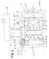
- the cam plate 42 or 43 is rotatably mounted with a guide sleeve 46 on a fixed hollow pin 47. This in turn is mounted on a load-bearing element of the packaging machine, in the exemplary embodiment of FIG. 4 on a gear housing 48.
- the shaft journal 27, the drive of which is located in the gear housing 48, passes through the hollow journal 46.
- the crank disc 42 or 43 only executes a rotary movement along the angle 36 during the standstill phase of the turret 10, namely for adjusting the turret arms 28.
- This reciprocating rotary movement is generated by a push rod 49, which is articulated to the cam plate 42 or 43.
- the push rod 49 is suitably driven, e.g. by a pressure medium cylinder (not shown).
- the packs 11 are introduced via a horizontal pack track 50 into the pocket 17 facing them together with the outer wrapper 12.
- the lower or rearward tubular flap 15 is folded over against the outer side surface 16 of the pack 11 by a folding finger 52.
- the upper or front tubular tab 14 is also folded over against the side surface 16, specifically by means of a stationary, curved guide wall 53 which extends lengthways a pitch circle outside the range of motion of the turret 10 extends.
- the overlapping tubular tabs 14, 15 are sealed or pre-sealed by a first sealing member 54.
- the tube tabs 14, 15 are sealed (final sealed) by a further, second sealing element 55.
- the finished package 11 is pushed out of the horizontally lying pocket 17 into a likewise horizontally directed discharge path 56.
- a pusher 57 comes into effect, which is arranged so that it can be moved back and forth between the turret arms 28 ... 31.
- the movement phase of the folding turret is preferably 120 ° of a work cycle.
- the entire standstill phase is 240 °.
- the standstill phase is expediently divided into two partial phases of 120 ° each.
- a first standstill phase of 120 ° the tubular flaps 14 and 15 are sealed by the sealing members 54 and 55.
- the side walls 18, 19 of the pockets 17 remain in the closed or clamped position, that is to say in the narrow position.
- the side walls 18, 19 are moved apart, that is to say the pockets 17 are opened.
- the packs 11 can now be pushed in and out.
Landscapes
- Engineering & Computer Science (AREA)
- Mechanical Engineering (AREA)
- Basic Packing Technique (AREA)
- Supplying Of Containers To The Packaging Station (AREA)
- Package Closures (AREA)
- Specific Conveyance Elements (AREA)
- Auxiliary Devices For And Details Of Packaging Control (AREA)
Applications Claiming Priority (2)
| Application Number | Priority Date | Filing Date | Title |
|---|---|---|---|
| DE3627912 | 1986-08-16 | ||
| DE19863627912 DE3627912A1 (de) | 1986-08-16 | 1986-08-16 | Revolver fuer verpackungsmaschinen |
Publications (3)
| Publication Number | Publication Date |
|---|---|
| EP0256332A2 true EP0256332A2 (fr) | 1988-02-24 |
| EP0256332A3 EP0256332A3 (en) | 1989-01-25 |
| EP0256332B1 EP0256332B1 (fr) | 1992-06-03 |
Family
ID=6307591
Family Applications (1)
| Application Number | Title | Priority Date | Filing Date |
|---|---|---|---|
| EP87110517A Expired - Lifetime EP0256332B1 (fr) | 1986-08-16 | 1987-07-21 | Révolver pour machines d'emballage |
Country Status (7)
| Country | Link |
|---|---|
| US (1) | US4790115A (fr) |
| EP (1) | EP0256332B1 (fr) |
| JP (1) | JPH0780562B2 (fr) |
| CN (1) | CN1007340B (fr) |
| BR (1) | BR8704218A (fr) |
| CA (1) | CA1325376C (fr) |
| DE (2) | DE3627912A1 (fr) |
Cited By (3)
| Publication number | Priority date | Publication date | Assignee | Title |
|---|---|---|---|---|
| GB2228914A (en) * | 1989-03-01 | 1990-09-12 | Zentrag Rationalisierung | Wrapping apparatus |
| WO2017045906A1 (fr) * | 2015-09-17 | 2017-03-23 | Khs Gmbh | Transporteur de contenants |
| EP4316997A3 (fr) * | 2022-08-03 | 2024-04-17 | Sacmi Packaging & Chocolate S.P.A. | Ensemble d'emballage pour produits sensiblement plats |
Families Citing this family (21)
| Publication number | Priority date | Publication date | Assignee | Title |
|---|---|---|---|---|
| IT1233785B (it) * | 1989-05-09 | 1992-04-17 | Gd Spa | Macchina incartatrice di prodotti sostanzialmente parallelepipedi |
| IT1234736B (it) * | 1989-08-02 | 1992-05-26 | Sarcmi Spa | Stella di guida e trasferimento regolabile per contenitori aventi una sezione circolare e non. |
| EP0473320A1 (fr) * | 1990-08-15 | 1992-03-04 | Philip Morris Products Inc. | Appareil et méthode pour former des boites à couvercle articulé pour cigarettes |
| US5179817A (en) * | 1990-08-15 | 1993-01-19 | Philip Morris Incorporated | Method where exposed foil on top of cigarette bundle is flat with no apparent folds |
| IT1242615B (it) * | 1990-12-12 | 1994-05-16 | Gd Spa | Metodo di incarto e saldatura in una macchina cellofanatrice. |
| IT1246011B (it) * | 1991-06-21 | 1994-11-07 | Gd Spa | Metodo e dispositivo per la realizzazione di giunzioni di costa di chiusura di incarti di prodotti. |
| US5657855A (en) * | 1993-06-23 | 1997-08-19 | The Meyercord Co. | Indicia applicator for cigarette packages |
| DE19528200A1 (de) * | 1995-08-01 | 1997-02-06 | Topack Verpacktech Gmbh | Vorrichtung zum Überführen von Packungsblöcken aus stabförmigen Artikeln der tabakverarbeitenden Industrie |
| DE19706215A1 (de) * | 1997-02-18 | 1998-08-20 | Focke & Co | Verpackungsmaschine, insbesondere für die Fertigung von Zigaretten-Packungen |
| JP2002145444A (ja) * | 2000-11-09 | 2002-05-22 | Okamura Corp | 搬送装置における薄板状搬送物の反転装置 |
| US6865862B2 (en) * | 2000-11-20 | 2005-03-15 | C.G. Bretting Mfg. Co., Inc. | Log bander apparatus and method |
| US8668071B2 (en) * | 2009-10-09 | 2014-03-11 | Tetra Laval Holdings & Finance S.A. | Turning wheel |
| CN101823570A (zh) * | 2010-05-20 | 2010-09-08 | 云南烟草科学研究院 | 卷烟透明纸包装机新型八角轮 |
| CN102689708B (zh) * | 2012-06-01 | 2014-02-26 | 郭宇斌 | 一种码垛包装机 |
| ES2623472T3 (es) * | 2013-08-23 | 2017-07-11 | Hinterkopf Gmbh | Dispositivo de transporte, sistema de mecanizado y procedimiento para el transporte y mecanizado de una pieza de trabajo |
| CN107074380B (zh) * | 2014-10-31 | 2019-08-16 | Cps有限责任公司 | 具有圆盘传送器的包装机 |
| CN106428798A (zh) * | 2016-12-09 | 2017-02-22 | 重庆明杰塑胶有限公司 | 一种用于塑料颗粒下料系统的转动架 |
| CN106742282B (zh) * | 2017-01-24 | 2023-03-21 | 昕迪精密机械(东莞)有限公司 | 一种叠包集装机 |
| CN111634462B (zh) * | 2020-05-06 | 2022-07-26 | 湖北中烟工业有限责任公司 | 一种适用于透明纸折叠成型气路优化装置 |
| CN113697192A (zh) * | 2021-08-25 | 2021-11-26 | 温州安创机械科技有限公司 | 新型转盘式纸塑包装机 |
| CN116002131A (zh) * | 2023-01-05 | 2023-04-25 | 常州金坛超创电池有限公司 | 一种扣式锂锰电池整理收集装置 |
Citations (2)
| Publication number | Priority date | Publication date | Assignee | Title |
|---|---|---|---|---|
| US2633279A (en) * | 1940-07-03 | 1953-03-31 | Redington Co F B | Packaging machine transfer mechanism |
| FR1480546A (fr) * | 1966-05-18 | 1967-05-12 | Focke Pfuhl Verpack Automat | Dispositif pour envelopper et cacheter complètement, de façon continue, dans des feuilles, notamment des paquets de cigarettes |
Family Cites Families (12)
| Publication number | Priority date | Publication date | Assignee | Title |
|---|---|---|---|---|
| US1309935A (en) * | 1919-07-15 | calleson | ||
| US1758929A (en) * | 1928-06-27 | 1930-05-20 | John J Cain | Method of making metal barrels and the like |
| US2324312A (en) * | 1941-02-20 | 1943-07-13 | Meyer Geo J Mfg Co | Bottle feeding mechanism |
| US3310149A (en) * | 1966-06-20 | 1967-03-21 | Fmc Corp | Carton transfer apparatus |
| US3396506A (en) * | 1966-07-22 | 1968-08-13 | Tabak & Ind Masch | Article-packing machines |
| GB1322707A (en) * | 1969-08-25 | 1973-07-11 | Molins Machine Co Ltd | Packing or wrapping machines the mould wheel type |
| JPS572594B2 (fr) * | 1974-01-31 | 1982-01-18 | ||
| US3957154A (en) * | 1974-01-29 | 1976-05-18 | Hitachi Shipbuilding And Engineering Co., Ltd. | Apparatus for rotating bottles |
| US4352265A (en) * | 1979-10-15 | 1982-10-05 | Otto Hansel Gmbh | Apparatus for producing bar packages of preferably individually wrapped sweets or similar pieces of confectionery |
| SE436272B (sv) * | 1981-03-27 | 1984-11-26 | Tetra Pak Int | Maskin for bearbetning av forpackningsbehallare |
| DD204072A1 (de) * | 1982-03-09 | 1983-11-16 | Rolf Schwanitz | Vorrichtung zum herstellen eines einschlages an weichkaramellen |
| JPS6023109A (ja) * | 1983-07-12 | 1985-02-05 | 日本たばこ産業株式会社 | ア−バタ−レツト包装機における包装紙押え装置 |
-
1986
- 1986-08-16 DE DE19863627912 patent/DE3627912A1/de not_active Withdrawn
-
1987
- 1987-07-21 EP EP87110517A patent/EP0256332B1/fr not_active Expired - Lifetime
- 1987-07-21 DE DE8787110517T patent/DE3779514D1/de not_active Expired - Lifetime
- 1987-08-07 US US07/082,611 patent/US4790115A/en not_active Expired - Lifetime
- 1987-08-10 CA CA000544112A patent/CA1325376C/fr not_active Expired - Fee Related
- 1987-08-13 JP JP62201046A patent/JPH0780562B2/ja not_active Expired - Fee Related
- 1987-08-14 BR BR8704218A patent/BR8704218A/pt not_active IP Right Cessation
- 1987-08-15 CN CN87105662A patent/CN1007340B/zh not_active Expired
Patent Citations (2)
| Publication number | Priority date | Publication date | Assignee | Title |
|---|---|---|---|---|
| US2633279A (en) * | 1940-07-03 | 1953-03-31 | Redington Co F B | Packaging machine transfer mechanism |
| FR1480546A (fr) * | 1966-05-18 | 1967-05-12 | Focke Pfuhl Verpack Automat | Dispositif pour envelopper et cacheter complètement, de façon continue, dans des feuilles, notamment des paquets de cigarettes |
Cited By (3)
| Publication number | Priority date | Publication date | Assignee | Title |
|---|---|---|---|---|
| GB2228914A (en) * | 1989-03-01 | 1990-09-12 | Zentrag Rationalisierung | Wrapping apparatus |
| WO2017045906A1 (fr) * | 2015-09-17 | 2017-03-23 | Khs Gmbh | Transporteur de contenants |
| EP4316997A3 (fr) * | 2022-08-03 | 2024-04-17 | Sacmi Packaging & Chocolate S.P.A. | Ensemble d'emballage pour produits sensiblement plats |
Also Published As
| Publication number | Publication date |
|---|---|
| DE3627912A1 (de) | 1988-02-18 |
| CA1325376C (fr) | 1993-12-21 |
| DE3779514D1 (de) | 1992-07-09 |
| US4790115A (en) | 1988-12-13 |
| EP0256332B1 (fr) | 1992-06-03 |
| JPH0780562B2 (ja) | 1995-08-30 |
| BR8704218A (pt) | 1988-04-12 |
| CN1007340B (zh) | 1990-03-28 |
| CN87105662A (zh) | 1988-03-09 |
| EP0256332A3 (en) | 1989-01-25 |
| JPS6351215A (ja) | 1988-03-04 |
Similar Documents
| Publication | Publication Date | Title |
|---|---|---|
| EP0256332B1 (fr) | Révolver pour machines d'emballage | |
| EP0197368B1 (fr) | Procédé et dispositif pour l'empaquetage, en particulier de cigarettes | |
| DE1511713C3 (de) | Maschine zum Verpacken von Zigaretten | |
| DE3123496C2 (fr) | ||
| DE2440006A1 (de) | Verfahren und vorrichtung zum herstellen und fuellen von klappschachteln aus faltbarem werkstoff, vorzugsweise fuer zigaretten | |
| EP0078066A2 (fr) | Dispositif pour l'emballage des cigarettes ou objets analogues | |
| EP0372314B1 (fr) | Dispositif pour le retournement d'un emballage | |
| DE2755071A1 (de) | Etikettiermaschine | |
| EP0433657B1 (fr) | Procédé et dispositif pour fabriquer des paquets (à cigarettes) | |
| WO2003045783A1 (fr) | Procede et dispositif de production d'emballages rigides pour des cigarettes | |
| DE3824316A1 (de) | Verfahren und vorrichtung zum herstellen einer quaderfoermigen packung | |
| DE2545256C2 (de) | Vorrichtung zum Herstellen bzw. Schließen von Packungen, insbesondere quaderförmigen Zigaretten-Packungen | |
| DE1980633U (de) | Zigaretten-verpackungsmaschine. | |
| EP0304736A2 (fr) | Procédé et dispositif pour envelopper spécialement des paquets de cigarettes | |
| DE2718953C2 (fr) | ||
| DE3939559C2 (de) | Maschine zur Verpackung von Zigaretten | |
| EP0850837B1 (fr) | Machine d'emballage pour la production de paquets de cigarettes | |
| DE1586046B1 (de) | Vorrichtung zum Verpacken von Zigaretten in Weichpackungen | |
| DE934150C (de) | Faltvorrichtungen an Packmaschinen, insbesondere zum Einwickeln von Zigaretten | |
| EP1960269A1 (fr) | Procede et dispositif pour entourer des emballages | |
| DE4224566C2 (de) | Austrag-Förderereinheit für Verpackungsmaschinen | |
| DE2354785A1 (de) | Revolver fuer einen schnellaufenden bodenfaltungspacker | |
| DE4001587C1 (en) | Feed magazine for cigarette packing machine - gathers cigarettes in pockets on conveyor belt | |
| DE2462974C2 (de) | Vorrichtung zum Herstellen von (quaderförmigen) Packungen | |
| DE3417154C2 (fr) |
Legal Events
| Date | Code | Title | Description |
|---|---|---|---|
| PUAI | Public reference made under article 153(3) epc to a published international application that has entered the european phase |
Free format text: ORIGINAL CODE: 0009012 |
|
| AK | Designated contracting states |
Kind code of ref document: A2 Designated state(s): DE FR GB IT |
|
| PUAL | Search report despatched |
Free format text: ORIGINAL CODE: 0009013 |
|
| AK | Designated contracting states |
Kind code of ref document: A3 Designated state(s): DE FR GB IT |
|
| 17P | Request for examination filed |
Effective date: 19890711 |
|
| 17Q | First examination report despatched |
Effective date: 19901031 |
|
| GRAA | (expected) grant |
Free format text: ORIGINAL CODE: 0009210 |
|
| AK | Designated contracting states |
Kind code of ref document: B1 Designated state(s): DE FR GB IT |
|
| GBT | Gb: translation of ep patent filed (gb section 77(6)(a)/1977) | ||
| REF | Corresponds to: |
Ref document number: 3779514 Country of ref document: DE Date of ref document: 19920709 |
|
| ITF | It: translation for a ep patent filed |
Owner name: STUDIO JAUMANN |
|
| ET | Fr: translation filed | ||
| PLBE | No opposition filed within time limit |
Free format text: ORIGINAL CODE: 0009261 |
|
| STAA | Information on the status of an ep patent application or granted ep patent |
Free format text: STATUS: NO OPPOSITION FILED WITHIN TIME LIMIT |
|
| 26N | No opposition filed | ||
| PGFP | Annual fee paid to national office [announced via postgrant information from national office to epo] |
Ref country code: FR Payment date: 20010712 Year of fee payment: 15 |
|
| REG | Reference to a national code |
Ref country code: GB Ref legal event code: IF02 |
|
| PGFP | Annual fee paid to national office [announced via postgrant information from national office to epo] |
Ref country code: DE Payment date: 20020731 Year of fee payment: 16 |
|
| PG25 | Lapsed in a contracting state [announced via postgrant information from national office to epo] |
Ref country code: FR Free format text: LAPSE BECAUSE OF NON-PAYMENT OF DUE FEES Effective date: 20030331 |
|
| REG | Reference to a national code |
Ref country code: FR Ref legal event code: ST |
|
| PGFP | Annual fee paid to national office [announced via postgrant information from national office to epo] |
Ref country code: GB Payment date: 20030716 Year of fee payment: 17 |
|
| PG25 | Lapsed in a contracting state [announced via postgrant information from national office to epo] |
Ref country code: DE Free format text: LAPSE BECAUSE OF NON-PAYMENT OF DUE FEES Effective date: 20040203 |
|
| PG25 | Lapsed in a contracting state [announced via postgrant information from national office to epo] |
Ref country code: GB Free format text: LAPSE BECAUSE OF NON-PAYMENT OF DUE FEES Effective date: 20040721 |
|
| GBPC | Gb: european patent ceased through non-payment of renewal fee |
Effective date: 20040721 |
|
| PG25 | Lapsed in a contracting state [announced via postgrant information from national office to epo] |
Ref country code: IT Free format text: LAPSE BECAUSE OF NON-PAYMENT OF DUE FEES;WARNING: LAPSES OF ITALIAN PATENTS WITH EFFECTIVE DATE BEFORE 2007 MAY HAVE OCCURRED AT ANY TIME BEFORE 2007. THE CORRECT EFFECTIVE DATE MAY BE DIFFERENT FROM THE ONE RECORDED. Effective date: 20050721 |