EP0256332A2 - Revolver for packing machines - Google Patents
Revolver for packing machines Download PDFInfo
- Publication number
- EP0256332A2 EP0256332A2 EP87110517A EP87110517A EP0256332A2 EP 0256332 A2 EP0256332 A2 EP 0256332A2 EP 87110517 A EP87110517 A EP 87110517A EP 87110517 A EP87110517 A EP 87110517A EP 0256332 A2 EP0256332 A2 EP 0256332A2
- Authority
- EP
- European Patent Office
- Prior art keywords
- turret
- pockets
- partial
- revolver
- side walls
- Prior art date
- Legal status (The legal status is an assumption and is not a legal conclusion. Google has not performed a legal analysis and makes no representation as to the accuracy of the status listed.)
- Granted
Links
Images


Classifications
-
- B—PERFORMING OPERATIONS; TRANSPORTING
- B65—CONVEYING; PACKING; STORING; HANDLING THIN OR FILAMENTARY MATERIAL
- B65B—MACHINES, APPARATUS OR DEVICES FOR, OR METHODS OF, PACKAGING ARTICLES OR MATERIALS; UNPACKING
- B65B51/00—Devices for, or methods of, sealing or securing package folds or closures; Devices for gathering or twisting wrappers, or necks of bags
- B65B51/10—Applying or generating heat or pressure or combinations thereof
-
- B—PERFORMING OPERATIONS; TRANSPORTING
- B65—CONVEYING; PACKING; STORING; HANDLING THIN OR FILAMENTARY MATERIAL
- B65B—MACHINES, APPARATUS OR DEVICES FOR, OR METHODS OF, PACKAGING ARTICLES OR MATERIALS; UNPACKING
- B65B11/00—Wrapping, e.g. partially or wholly enclosing, articles or quantities of material, in strips, sheets or blanks, of flexible material
- B65B11/06—Wrapping articles, or quantities of material, by conveying wrapper and contents in common defined paths
- B65B11/28—Wrapping articles, or quantities of material, by conveying wrapper and contents in common defined paths in a curved path, e.g. on rotary tables or turrets
Definitions
- the invention relates to a revolver with pockets arranged along the circumference for holding objects, in particular packs, the pockets being delimited by at least two (parallel) side walls.
- Revolvers are rotatingly driven organs for the transport of packages or package contents in connection with packaging machines.
- a revolver is provided with pockets on the outer circumference, each of which contains the contents of the pack or the packs, which may have already been partially completed.
- manipulations are carried out on them, in particular Folding processes as well as welding or gluing of blanks.
- the centrifugal forces can lead to the undesired relative displacements within the pockets. This is especially true if the package contents, e.g. a single item with considerable play is included in the pack.
- the invention has for its object to develop and develop a (folding) turret of the type described above so that even at high speeds of rotation packs and other objects within the pockets of the turret are avoided.
- the turret according to the invention is characterized in that the side walls of the pockets to enlarge or reduce the Cross-section for the object or the package are movable relative to each other.
- the revolver consists of (two) partial revolvers, each of which is movable with one of the side walls of a pocket.
- the partial revolvers can be rotated about a common axis.
- An actuator can be controlled so that the partial revolvers - and thus the side walls of the pockets - perform a short relative stroke to one another during the standstill phases, so that the cross-section of the pockets is slightly expanded or narrowed.
- the objects or packs can be inserted or ejected into them.
- the cross section of the pockets is narrowed so that the contents of the pockets are fixed under clamping action. This prevents the objects or packs from being able to be moved in the pockets open on the radially outer side as a result of centrifugal forces.
- the turret 10 shown is used in conjunction with or as part of a packaging machine.
- it is an example of the wrapping of elongated packs 11 in an outer wrapper 12 made of cellophane or plastic.
- the pack 11 made of (thin) cardboard has been manufactured and filled in the area of other units of the packaging machine.
- the content of the pack 11 is a solid, single object, namely a tube 13. This is accommodated with play in the pack 11, which is rectangular in cross section, so that the tube 13 can carry out relative movements within the pack 11.
- tubular tabs 14 and 15 of the outer covering 12 are folded over one after the other against the associated radially outward-facing side surface 16 of the pack 11 and finally connected to one another by sealing. Furthermore, end folds can be carried out by folding members, which are not shown in the drawings.
- the turret 10 has a plurality of, in the present case six pockets 17. These are delimited in the circumferential direction of the turret 10 by side walls 18 and 19. The radially outer side of the pockets is open, so that the packs 11 can be inserted and pushed out of a (horizontally directed) pocket 17 by radial displacement.
- the pockets 17 are further delimited by end walls 20 and 21 acting in the axial direction.
- the radial end of the pockets 17 is formed by a bottom wall 22.
- At least the side walls 18 and 19 can be moved relative to one another, in the sense of expanding or reducing the free cross section of the pockets 17.
- the packs 11 can be inserted without problems in the region of an insertion station 23 into a horizontally directed pocket 17 , namely together with the U-shaped outer wrapping 12 around the pack 11.
- the packs 11 finished in relation to the outer wrapper 12 are pushed out again in the region of an ejection station 24 from a likewise horizontally directed pocket 17 in the radial direction.
- the clockwise movement of the revolver 10 takes place in the example shown in the counterclockwise direction, so that the (two) pockets 17 filled with packs 11 are directed upwards in the region between the insertion station 23 and the extension station 24.
- a cross-sectional expansion of the pockets 17 by moving the side walls 18, 19 apart therefore does not result in the packs 11 being able to slide out of the pockets 17 pointing upwards.
- the turret 10 consists of several, namely here of two partial turrets 25 and 26. These are each assigned one of the side walls 18 and 19. With relative adjustment of the partial revolvers 25, 26 to one another, therefore, the side walls 18, 19 are also adjusted as part of one or the other partial revolvers 25, 26.
- the partial revolvers 25 and 26 together form the revolver 10 and can be rotated as a unit.
- the partial revolvers 25 and 26 can be rotated about a common axis.
- the partial turret 26 is firmly connected to a drive shaft or a shaft journal 27.
- the partial turret 25, however, is rotatably mounted on the shaft journal 27.
- the partial revolvers 25 and 26 in the present case each consist of approximately radially directed revolver arms 28, 29 and 30, 31. At the ends of these arms 28, 29 and 30, 31, the side walls 18 and 19 are arranged, but not over the Full length of the revolver 10 continuously, but only as a short or narrow leg.
- the packs 11 are therefore not covered over their entire length within a pocket 17 by side walls 18, 19 and the bottom wall 22, but only at the ends of the elongated packs 11.
- Each pocket 17 accordingly consists of two end pockets for receiving the end regions of the pack 11 This is exposed in the middle area between arms 28 or 29 and 30 or 31.
- the bottom wall 22 in the area of the turret arms 30 and 31 is dimensioned in the axial direction as well as the side walls 19 arranged on the same turret arms 30, 31.
- the turret arms 28 and 29 assigned to the side walls 18 of a pocket 17 are fastened at an axial distance from one another in each case to a collar 32, 33 on the shaft journal 27 or at the end thereof. Between the collars 32, 33, the partial turret 25 is mounted on the shaft journal 27, specifically with a continuous rotating sleeve 34.
- the partial revolvers 25, 26 are adjustable relative to one another along an angle 36 by means of an actuating gear 35.
- the Actuator 35 consists of a toggle lever arrangement with tabs 37 and 38. These are each articulated or pivotally connected to the sides of adjacent turret arms 28 on the one hand and 30 on the other.
- the two tabs 37 and 38 are brought together in a common joint 39.
- a feeler roller 40 is mounted in this.
- the actuating gear 35 consisting of the tabs 37 and 38 is loaded in the direction of moving the side walls 18 and 19 of the pockets 17 together, that is to say in the direction of a reduction in the pocket cross section.
- a tension spring 41 anchored to the turret 10 at the other end acts on the knee joint, namely in the common joint 39.
- the tension spring 41 is only effective. This means that a force reducing the cross section of the pockets 17 is exerted on the partial revolvers 25, 26. The packs 11 are held in the pockets during this phase under clamping action.
- the partial revolvers 25, 26 move relative to each other in the sense of a movement of the side walls 18, 19 apart.
- the knee joint is acted upon against the force of the tension spring 41 in the sense of a reduction in the angular position between the tabs 37 and 38 .
- An actuator acts on the feeler roller 40 of the tabs 37 and 38 in the sense of a radially outward movement.
- the adjustment is effected by a cam 42 or 43.
- the feeler roller 40 runs on the outer circumference of the cam plate 42 when the tabs 37, 38 are adjusted.
- cam cam 44 acts on the feeler roller 40 and thus pivots the tabs 37, 38 such that the adjacent turret arms 28 and 30 are moved towards each other.
- an analog cam groove 45 is provided, in which the feeler roller 40 runs during the actuating movement.
- the cams 42, 43 are arranged concentrically with the turret 10, so that during the (cyclical) rotary movement of the turret 10 the feeler roller 40 can run outside the cam cams 44 on the cam 42 or in the cam groove 45 of the cam 43.
- the cam plate 42 or 43 is rotatably mounted with a guide sleeve 46 on a fixed hollow pin 47. This in turn is mounted on a load-bearing element of the packaging machine, in the exemplary embodiment of FIG. 4 on a gear housing 48.
- the shaft journal 27, the drive of which is located in the gear housing 48, passes through the hollow journal 46.
- the crank disc 42 or 43 only executes a rotary movement along the angle 36 during the standstill phase of the turret 10, namely for adjusting the turret arms 28.
- This reciprocating rotary movement is generated by a push rod 49, which is articulated to the cam plate 42 or 43.
- the push rod 49 is suitably driven, e.g. by a pressure medium cylinder (not shown).
- the packs 11 are introduced via a horizontal pack track 50 into the pocket 17 facing them together with the outer wrapper 12.
- the lower or rearward tubular flap 15 is folded over against the outer side surface 16 of the pack 11 by a folding finger 52.
- the upper or front tubular tab 14 is also folded over against the side surface 16, specifically by means of a stationary, curved guide wall 53 which extends lengthways a pitch circle outside the range of motion of the turret 10 extends.
- the overlapping tubular tabs 14, 15 are sealed or pre-sealed by a first sealing member 54.
- the tube tabs 14, 15 are sealed (final sealed) by a further, second sealing element 55.
- the finished package 11 is pushed out of the horizontally lying pocket 17 into a likewise horizontally directed discharge path 56.
- a pusher 57 comes into effect, which is arranged so that it can be moved back and forth between the turret arms 28 ... 31.
- the movement phase of the folding turret is preferably 120 ° of a work cycle.
- the entire standstill phase is 240 °.
- the standstill phase is expediently divided into two partial phases of 120 ° each.
- a first standstill phase of 120 ° the tubular flaps 14 and 15 are sealed by the sealing members 54 and 55.
- the side walls 18, 19 of the pockets 17 remain in the closed or clamped position, that is to say in the narrow position.
- the side walls 18, 19 are moved apart, that is to say the pockets 17 are opened.
- the packs 11 can now be pushed in and out.
Abstract
Ein Faltrevolver (10) zur Aufnahme von Packungen (11) oder anderen Gegenständen in Taschen (17) besteht aus Teilrevolvern (25, 26), die während einer Stillstandsphase des Revolvers gegeneinander verstellbar sind, derart, daß der Querschnitt der Taschen (17) zeitweilig vergrößert und danach wieder verkleinert wird. Während der Drehbewegung des Faltrevolvers haben die Taschen (17) einen verringerten Querschnitt, der eine Fixierung der Packungen (11) durch Klemmwirkung innerhalb der Taschen (17) bewirkt.A folding turret (10) for holding packs (11) or other objects in pockets (17) consists of partial revolvers (25, 26) which can be adjusted relative to one another during a standstill phase of the revolver, such that the cross section of the pockets (17) is temporary is enlarged and then reduced again. During the rotational movement of the folding turret, the pockets (17) have a reduced cross-section, which causes the packs (11) to be fixed by means of a clamping effect within the pockets (17).
Description
Die Erfindung betrifft einen Revolver mit längs des Umfangs angeordneten Taschen zur Aufnahme von Gegenständen, insbesondere Packungen, wobei die Taschen durch wenigstens zwei (parallele) Seitenwände begrenzt sind.The invention relates to a revolver with pockets arranged along the circumference for holding objects, in particular packs, the pockets being delimited by at least two (parallel) side walls.
Revolver sind drehend angetriebene Organe für den Transport von Packungen bzw. Packungsinhalt im Zusammenhang mit Verpackungsmaschinen. Am äußeren Umfang ist ein Revolver mit Taschen versehen, in denen jeweils der Packungsinhalt bzw. die gegebenenfalls bereits teilweise fertiggestellten Packungen Aufnahme finden. Während des Transports der Gegenstände (mit Verpackungs-Zuschnitt) bzw. der Verpackungen werden Manipulationen an diesen ausgeführt, insbesondere Faltvorgänge sowie Schweißungen oder Verklebungen von Zuschnitten.Revolvers are rotatingly driven organs for the transport of packages or package contents in connection with packaging machines. A revolver is provided with pockets on the outer circumference, each of which contains the contents of the pack or the packs, which may have already been partially completed. During the transport of the objects (with packaging cut) or the packaging, manipulations are carried out on them, in particular Folding processes as well as welding or gluing of blanks.
Bei Einsatz in hochleistungsfähigen Verpackungsmaschinen sind hohe Drehgeschwindigkeiten der Faltrevolver erforderlich, wenn die kurzen Taktzeiten erreicht werden sollen. Vor allem bei schrittweise drehenden Faltrevolvern ergeben sich notwendigerweise hohe Drehgeschwindigkeiten, weil die Stillstandsphase für die Durchführung der erforderlichen Maßnahmen an den Packungen möglichst kurz sein soll. Die hohen Drehgeschwindigkeiten können zu unerwünschten Verschiebungen der Packungen in den Taschen führen. Dies gilt insbesondere für Revolver, bei denen die Taschen auf der radial außenliegenden Seite offen sind, um die Gegenstände und Packungen durch Radialbewegung in die Taschen ein- bzw. aus diesen ausschieben zu können. Da die Abmessungen der Taschen, nämlich die Abstände der diese begrenzenden Seitenwände voneinander auf die Abmessungen der Packungen bzw. des Packungsinhalts abgestellt sind, können die Zentrifugalkräfte zu den unerwünschten Relativverschiebungen innerhalb der Taschen führen. Dies gilt vor allem dann, wenn der Packungsinhalt, z.B. ein einzelner Gegenstand, mit erheblichem Spiel in der Packung Aufnahme findet.When used in high-performance packaging machines, high revolving speeds of the folding turret are required if the short cycle times are to be achieved. Especially with step-by-step folding turrets, there are necessarily high speeds of rotation because the standstill phase for carrying out the necessary measures on the packs should be as short as possible. The high rotational speeds can lead to undesirable displacements of the packs in the pockets. This applies in particular to revolvers in which the pockets on the radially outer side are open in order to be able to push the objects and packs into or out of the pockets by radial movement. Since the dimensions of the pockets, namely the spacing of the side walls delimiting them from one another, are based on the dimensions of the packs or of the pack contents, the centrifugal forces can lead to the undesired relative displacements within the pockets. This is especially true if the package contents, e.g. a single item with considerable play is included in the pack.
Der Erfindung liegt die Aufgabe zugrunde, einen (Falt-)Revolver der eingangs beschriebenen Art so auszubilden und weiterzuentwickeln, daß auch bei hohen Drehgeschwindigkeiten Verschiebungen von Packungen und anderen Gegenständen innerhalb der Taschen des Revolvers vermieden werden.The invention has for its object to develop and develop a (folding) turret of the type described above so that even at high speeds of rotation packs and other objects within the pockets of the turret are avoided.
Zur Lösung dieser Aufgabe ist der erfindungsgemäße Revolver dadurch gekennzeichnet, daß die Seitenwände der Taschen zur Vergrößerung oder Verkleinerung des Querschnitts für den Gegenstand bzw. die Packung relativ zueinander bewegbar sind.To solve this problem, the turret according to the invention is characterized in that the side walls of the pockets to enlarge or reduce the Cross-section for the object or the package are movable relative to each other.
Durch die Bewegbarkeit der den Innenraum bzw. die Innenabmessung der Tasche bestimmenden Seitenwände derselben ist es möglich, für bestimmte Arbeitsphasen, nämlich für den Einschub und den Ausschub der Gegenstände und Packungen einen größeren Querschnitt der Taschen zu gewährleisten, hingegen während anderer Phasen, insbesondere während der Drehung des Faltrevolvers, den Packungsinhalt durch entsprechende Verringerung des Querschnitts der Taschen klemmend zu halten.Due to the mobility of the interior walls and the interior dimensions of the bag, it is possible to ensure a larger cross section of the bags for certain work phases, namely for the insertion and ejection of the objects and packs, on the other hand during other phases, in particular during the Rotation of the folding turret to keep the contents of the pack jammed by reducing the cross-section of the pockets accordingly.
Gemäß bevorzugter Ausführungsform der Erfindung besteht der Revolver aus (zwei) Teilrevolvern, die mit je einer der Seitenwände einer Tasche für sich bewegbar sind. Die Teilrevolver sind um eine gemeinsame Achse drehbar. Ein Stellgetriebe ist so steuerbar, daß während der Stillstandsphasen die Teilrevolver - und damit die Seitenwände der Taschen - einen kurzen Relativhub zueinander ausführen, so daß der Querschnitt der Taschen geringfügig erweitert bzw. verengt wird. In der Stellung bei vergrößertem Querschnitt der Taschen können die Gegenstände bzw. Packungen in diese eingeführt oder ausgestoßen werden. Während der Drehbewegung des Revolvers ist der Querschnitt der Taschen so verengt, daß der Inhalt derselben unter Klemmwirkung fixiert ist. Dadurch wird verhindert, daß die Gegenstände bzw. Packungen in den an der radial außenliegenden Seite offenen Taschen infolge von Zentrifugalkräften verschoben werden können.According to a preferred embodiment of the invention, the revolver consists of (two) partial revolvers, each of which is movable with one of the side walls of a pocket. The partial revolvers can be rotated about a common axis. An actuator can be controlled so that the partial revolvers - and thus the side walls of the pockets - perform a short relative stroke to one another during the standstill phases, so that the cross-section of the pockets is slightly expanded or narrowed. In the position with an enlarged cross section of the pockets, the objects or packs can be inserted or ejected into them. During the rotating movement of the revolver, the cross section of the pockets is narrowed so that the contents of the pockets are fixed under clamping action. This prevents the objects or packs from being able to be moved in the pockets open on the radially outer side as a result of centrifugal forces.
Weitere Merkmale der Erfindung betreffen die Ausgestaltung der Teilrevolver bzw. der Taschen sowie das Getriebe für die Relativverstellung der Teilrevolver zueinander.Further features of the invention relate to the design of the partial turret or the pockets and the gear for the relative adjustment of the partial turret to one another.
Ein Ausführungsbeispiel der Erfindung wird nachfolgend anhand der Zeichnungen näher erläutert. Es zeigt:
- Fig. 1 einen Faltrevolver in Seitenansicht in vereinfachter Darstellung,
- Fig. 2 einen Horizontalschnitt längs der Schnittebene II-II der Fig. 1,
- Fig. 3 eine Seitenansicht des Faltrevolvers gemäß Fig. 1 in verkleinertem Maßstab mit Stellgetriebe für Teilrevolver,
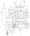
- Fig. 4 einen Horizontalschnitt durch den Faltrevolver gemäß Fig. 3.
- 1 is a folding turret in a side view in a simplified representation,
- 2 is a horizontal section along the section plane II-II of FIG. 1,
- 3 shows a side view of the folding turret according to FIG. 1 on a reduced scale with an actuating gear for partial turrets,
- 4 shows a horizontal section through the folding turret according to FIG. 3.
Der gezeigte Revolver 10 kommt in Verbindung mit bzw. als Teil einer Verpackungsmaschine zum Einsatz. Im vorliegenden Falle geht es als Beispiel um die Einhüllung von langgestreckten Packungen 11 in eine Außenumhüllung 12 aus Zellglas oder Kunststoff. Die Packung 11 aus (dünnem) Karton ist im Bereich anderer Aggregate der Verpackungsmaschine hergestellt und befüllt worden. Der Inhalt der Packung 11 ist bei diesem Beispiel ein fester, einzelner Gegenstand, nämlich eine Tube 13. Diese findet mit Spiel Aufnahme in der im Querschnitt rechteckigen Packung 11, so daß die Tube 13 innerhalb der Packung 11 Relativbewegungen ausführen kann.The
Im Bereich des Revolvers 10 werden Schlauchlappen 14 und 15 der Außenumhüllung 12 gegen die zugeordnete, radial nach außen weisende Seitenfläche 16 der Packung 11 nacheinander umgefaltet und schließlich durch Siegeln miteinander verbunden. Des weiteren können stirnseitige Faltungen durch Faltorgane ausgeführt werden, die in den Zeichnungen nicht dargestellt sind.In the area of the
Der Revolver 10 weist mehrere, im vorliegenden Falle sechs Taschen 17 auf. Diese werden in Umfangsrichtung des Revolvers 10 durch Seitenwände 18 und 19 begrenzt. Die radial außenliegende Seite der Taschen ist offen, so daß die Packungen 11 durch Radialverschiebung jeweils in eine (horizontal gerichtete) Tasche 17 eingeführt und aus dieser ausgeschoben werden können. Die Taschen 17 sind weiterhin durch in Axialrichtung wirkende Stirnwände 20 und 21 begrenzt. Der in Radialrichtung innenliegende Abschluß der Taschen 17 wird durch eine Bodenwand 22 gebildet.The
Mindestens die Seitenwände 18 und 19 sind relativ zueinander bewegbar, und zwar im Sinne einer Erweiterung oder Verringerung des freien Querschnitts der Taschen 17. Bei auseinanderbewegten Seitenwänden 18, 19 können die Packungen 11 störungsfrei im Bereich einer Einschubstation 23 in eine horizontal gerichtete Tasche 17 eingeführt werden, und zwar zusammen mit der sich U-förmig um die Packung 11 herumlegenden Außenumhüllung 12. Auf der gegenüberliegenden Seite werden die in bezug auf die Außenumhüllung 12 fertiggestellten Packungen 11 im Bereich einer Ausschubstation 24 aus einer ebenfalls horizontal gerichteten Tasche 17 in Radialrichtung wieder ausgeschoben. Die taktweise Bewegung des Revolvers 10 erfolgt bei dem gezeigten Beispiel im Gegenuhrzeigersinn, so daß die mit Packungen 11 befüllten (zwei) Taschen 17 im Bereich zwischen Einschubstation 23 und Ausschubstation 24 nach oben gerichtet sind. Eine Querschnittserweiterung der Taschen 17 durch Auseinanderbewegen der Seitenwände 18, 19 hat demnach nicht zur Folge, daß die Packungen 11 aus den nach oben gerichteten Taschen 17 herausgleiten können.At least the
Zur Durchführung der vorgenannten Veränderungen an den Taschen 17 besteht der Revolver 10 aus mehreren, nämlich hier aus zwei Teilrevolvern 25 und 26. Diesen ist je eine der Seitenwände 18 und 19 zugeordnet. Bei Relativ verstellung der Teilrevolver 25, 26 zueinander werden mithin auch die Seitenwände 18, 19 als Teil des einen oder anderen Teilrevolvers 25, 26 mit verstellt. Die Teilrevolver 25 und 26 bilden zusammen den Revolver 10 und sind als Einheit drehbar.To carry out the aforementioned changes to the
Die Teilrevolver 25 und 26 sind um eine gemeinsame Achse drehbar. Im vorliegenden Falle ist der Teilrevolver 26 fest mit einer Antriebswelle bzw. einem Wellenzapfen 27 verbunden. Der Teilrevolver 25 ist hingegen drehbar auf dem Wellenzapfen 27 gelagert.The
Die Teilrevolver 25 und 26 bestehen im vorliegenden Falle jeweils aus annähernd radial gerichteten Revolverarmen 28, 29 bzw. 30, 31. An den Enden dieser Arme 28, 29 bzw. 30, 31 sind die Seitenwände 18 bzw. 19 angeordnet, jedoch nicht über die volle Länge des Revolvers 10 durchgehend, sondern lediglich als kurze bzw. schmale Schenkel. Die Packungen 11 werden demnach nicht auf ihrer gesamten Länge innerhalb einer Tasche 17 durch Seitenwände 18, 19 und die Bodenwand 22 umfaßt, sondern lediglich an den Enden der langgestreckten Packungen 11. Jede Tasche 17 besteht demnach aus zwei Endtaschen zur Aufnahme der Endbereiche der Packung 11. Diese liegt im mittleren Bereich zwischen den Armen 28 bzw. 29 und 30 bzw. 31 frei. Auch die Bodenwand 22 ist im Bereich der Revolverarme 30 und 31 in Axialrichtung so bemessen wie die an denselben Revolverarmen 30, 31 angeordneten Seitenwände 19.The
Die den Seitenwänden 18 einer Tasche 17 zugeordneten Revolverarme 28 und 29 sind mit axialem Abstand voneinander jeweils an einem Bund 32, 33 auf dem Wellenzapfen 27 bzw. am Ende desselben befestigt. Zwischen den Bunden 32, 33 ist der Teilrevolver 25 auf dem Wellenzapfen 27 gelagert, und zwar mit einer durchgehenden Drehhülse 34.The
Die Teilrevolver 25, 26 sind durch ein Stellgetriebe 35 längs eines Winkels 36 gegeneinander verstellbar. Das Stellgetriebe 35 besteht aus Kniehebelanordnung mit den Laschen 37 und 38. Diese sind jeweils gelenkig bzw. schwenkbar mit den Seiten benachbarter Revolverarme 28 einerseits und 30 andererseits verbunden. Die beiden Laschen 37 und 38 werden in einem gemeinsamen Gelenk 39 zusammengeführt. In diesem ist eine Tastrolle 40 gelagert. Das aus den Laschen 37 und 38 bestehende Stellgetriebe 35 ist in Richtung auf ein Zusammenbewegen der Seitenwände 18 und 19 der Taschen 17 belastet, also in Richtung auf eine Verkleinerung des Taschenquerschnitts. Zu diesem Zweck greift an dem Kniegelenk, nämlich in dem gemeinsamen Gelenk 39, eine mit dem anderen Ende am Revolver 10 verankerte Zugfeder 41 an.The
Während der Drehbewegung des Revolvers 10 ist die Zugfeder 41 ausschließlich wirksam. Dies bedeutet, daß eine dem Querschnitt der Taschen 17 verringernde Kraft auf die Teilrevolver 25, 26 ausgeübt wird. Die Packungen 11 werden während dieser Phase in den Taschen unter Klemmwirkung gehalten.During the rotary movement of the
Während des Stillstands des Revolvers 10 erfolgt eine Relativbewegung der Teilrevolver 25, 26 zueinander im Sinne einer Auseinanderbewegung der Seitenwände 18, 19. Zu diesem Zweck wird gegen die Kraft der Zugfeder 41 das Kniegelenk im Sinne einer Verkleinerung der Winkelstellung zwischen den Laschen 37 und 38 beaufschlagt. Ein Stellorgan wirkt auf die Tastrolle 40 der Laschen 37 und 38 im Sinne einer radial nach außen gerichteten Bewegung. Bei dem gezeigten Ausführungsbeispiel wird die Verstellung durch eine Kurvenscheibe 42 bzw. 43 bewirkt. Bei der Ausführungsform nach Fig. 3 läuft die Tastrolle 40 bei der Verstellung der Laschen 37, 38 auf dem Außenumfang der Kurvenscheibe 42 ab. Diese ist jeweils im Bereich zwischen den Taschen 17 des Revolvers 10 mit einer Kurvennocke 44 versehen, die die Tastrolle 40 beaufschlagt und damit die Laschen 37, 38 verschwenkt, derart, daß die benachbarten Revolverarme 28 und 30 in Richtung zueinander bewegt werden. Bei der Alternativausführung der Kurvenscheibe 43 laut Fig. 4 ist eine analog ausgebildete Kurvennut 45 vorgesehen, in der die Tastrolle 40 bei der Stellbewegung abläuft.While the
Die Kurvenscheiben 42, 43 sind konzentrisch zum Revolver 10 angeordnet, so daß während der (taktweisen) Drehbewegung des Revolvers 10 die Tastrolle 40 außerhalb der Kurvennocken 44 auf der Kurvenscheibe 42 bzw. in der Kurvennut 45 der Kurvenscheibe 43 zu laufen vermag. Die Kurvenscheibe 42 bzw. 43 ist zu diesem Zweck drehbar mit einer Führungshülse 46 auf einem feststehenden Hohlzapfen 47 gelagert. Dieser wiederum ist an einem tragenden Element der Verpackungsmaschine gelagert, bei dem Ausführungsbeispiel der Fig. 4 an einem Getriebegehäuse 48. Durch den Hohlzapfen 46 tritt der Wellenzapfen 27 hindurch, dessen Antrieb sich in dem Getriebegehäuse 48 befindet. Die Kurbenscheibe 42 bzw. 43 führt lediglich während der Stillstandsphase des Revolvers 10, nämlich zur Verstellung der Revolverarme 28..31 zueinander, eine Drehbewegung längs des Winkels 36 aus. Diese hin- und hergehende Drehbewegung wird durch eine Schubstange 49 erzeugt, die gelenkig mit der Kurvenscheibe 42 bzw. 43 verbunden ist. Die Schubstange 49 wird in geeigneter Weise angetrieben, z.B. durch einen Druckmittelzylinder (nicht dargestellt).The
Bei dem in Fig 3 und 4 gezeigten Anwendungsbeispiel werden die Packungen 11 über eine horizontale Packungsbahn 50 in die dieser zugekehrten Tasche 17 samt Außenumhüllung 12 eingeführt. Nach Zurückgehen eines Schiebers 51 wird der untere bzw. in Drehrichtung rückwärtige Schlauchlappen 15 durch einen Faltfinger 52 gegen die äußere Seitenfläche 16 der Packung 11 umgefaltet. Bei der nachfolgenden Weiterbewegung des Revolvers 10 wird der obere bzw. vordere Schlauchlappen 14 ebenfalls gegen die Seitenfläche 16 umgefaltet, und zwar durch eine ortsfeste, gebogene Führungswand 53, die sich längs eines Teilkreises außerhalb des Bewegungsbereichs des Revolvers 10 erstreckt.In the application example shown in FIGS. 3 and 4, the
Während der nächsten Stillstandsphase werden die einander überdeckenden Schlauchlappen 14, 15 durch ein erstes Siegelorgan 54 gesiegelt bzw. vorgesiegelt. Bei der nächsten Stillstandsphase erfolgt ein weiteres Versiegeln (Endsiegeln) der Schlauchlappen 14, 15 durch ein weiteres, zweites Siegelorgan 55. Bei der danach folgenden Stillstandsphase wird die fertige Packung 11 aus der horizontal liegenden Tasche 17 in eine ebenfalls horizontal gerichtete Abförderbahn 56 eingeschoben. Hierfür kommt ein Ausschieber 57 zur Wirkung, der hin- und herbewegbar zwischen den Revolverarmen 28...31 angeordnet ist.During the next standstill phase, the overlapping
Durch die beschriebene Ausbildung des Revolvers 10 kann dieser verhältnismäßig schnelle Drehbewegungen bzw. Schalttakte ausführen. Dies wiederum ermöglicht größere Stillstandsphasen zum Ein- und Ausschieben der Packungen. Vorzugsweise beträgt die Bewegungsphase des Faltrevolvers 120° eines Arbeitstaktes. Die gesamte Stillstandsphase beträgt 240°. Die Stillstandsphase wird dabei zweckmäßigerweise in zwei Teilphasen von je 120° aufgeteilt. Während einer ersten Stillstandsphase von 120° erfolgt die Siegelung der Schlauchlappen 14 und 15 durch die Siegelorgane 54 und 55. Während dieser ersten Stillstandsphase bleiben die Seitenwänden 18, 19 der Taschen 17 in der Schließ- bzw. Klemmstellung, also in der engen Position. Während einer weiteren Stillstands-Teilphase von 120° werden die Seitenwände 18, 19 auseinanderbewegt, die Taschen 17 also geöffnet. Es kann nun das Ein- und Ausschieben der Packungen 11 erfolgen.Due to the described design of the
Claims (14)
Applications Claiming Priority (2)
| Application Number | Priority Date | Filing Date | Title |
|---|---|---|---|
| DE19863627912 DE3627912A1 (en) | 1986-08-16 | 1986-08-16 | REVOLVER FOR PACKAGING MACHINES |
| DE3627912 | 1986-08-16 |
Publications (3)
| Publication Number | Publication Date |
|---|---|
| EP0256332A2 true EP0256332A2 (en) | 1988-02-24 |
| EP0256332A3 EP0256332A3 (en) | 1989-01-25 |
| EP0256332B1 EP0256332B1 (en) | 1992-06-03 |
Family
ID=6307591
Family Applications (1)
| Application Number | Title | Priority Date | Filing Date |
|---|---|---|---|
| EP87110517A Expired - Lifetime EP0256332B1 (en) | 1986-08-16 | 1987-07-21 | Revolver for packing machines |
Country Status (7)
| Country | Link |
|---|---|
| US (1) | US4790115A (en) |
| EP (1) | EP0256332B1 (en) |
| JP (1) | JPH0780562B2 (en) |
| CN (1) | CN1007340B (en) |
| BR (1) | BR8704218A (en) |
| CA (1) | CA1325376C (en) |
| DE (2) | DE3627912A1 (en) |
Cited By (3)
| Publication number | Priority date | Publication date | Assignee | Title |
|---|---|---|---|---|
| GB2228914A (en) * | 1989-03-01 | 1990-09-12 | Zentrag Rationalisierung | Wrapping apparatus |
| WO2017045906A1 (en) * | 2015-09-17 | 2017-03-23 | Khs Gmbh | Container handling machine |
| EP4316997A3 (en) * | 2022-08-03 | 2024-04-17 | Sacmi Packaging & Chocolate S.P.A. | Packaging assembly for substantially flat products |
Families Citing this family (20)
| Publication number | Priority date | Publication date | Assignee | Title |
|---|---|---|---|---|
| IT1233785B (en) * | 1989-05-09 | 1992-04-17 | Gd Spa | WRAPPING MACHINE OF SUBSTANTIALLY PARALLELEPIPED PRODUCTS |
| IT1234736B (en) * | 1989-08-02 | 1992-05-26 | Sarcmi Spa | ADJUSTABLE GUIDE STAR AND TRANSFER FOR CONTAINERS HAVING A CIRCULAR SECTION AND NOT. |
| US5179817A (en) * | 1990-08-15 | 1993-01-19 | Philip Morris Incorporated | Method where exposed foil on top of cigarette bundle is flat with no apparent folds |
| EP0473320A1 (en) * | 1990-08-15 | 1992-03-04 | Philip Morris Products Inc. | Apparatus and method for forming hinged top cigarette box |
| IT1242615B (en) * | 1990-12-12 | 1994-05-16 | Gd Spa | WRAPPING AND WELDING METHOD IN A WRAPPING MACHINE. |
| IT1246011B (en) * | 1991-06-21 | 1994-11-07 | Gd Spa | METHOD AND DEVICE FOR THE REALIZATION OF COSTA JOINTS FOR CLOSURE OF PRODUCT WRAPS. |
| US5657855A (en) * | 1993-06-23 | 1997-08-19 | The Meyercord Co. | Indicia applicator for cigarette packages |
| DE19528200A1 (en) * | 1995-08-01 | 1997-02-06 | Topack Verpacktech Gmbh | Device for transferring pack blocks from rod-shaped articles of the tobacco processing industry |
| DE19706215A1 (en) * | 1997-02-18 | 1998-08-20 | Focke & Co | Packaging machine, in particular for the manufacture of cigarette packs |
| JP2002145444A (en) * | 2000-11-09 | 2002-05-22 | Okamura Corp | Reversal device for thin plate-like object to be conveyed in conveying device |
| US6865862B2 (en) * | 2000-11-20 | 2005-03-15 | C.G. Bretting Mfg. Co., Inc. | Log bander apparatus and method |
| WO2011042155A1 (en) * | 2009-10-09 | 2011-04-14 | Tetra Laval Holdings & Finance S.A. | Turning wheel |
| CN101823570A (en) * | 2010-05-20 | 2010-09-08 | 云南烟草科学研究院 | Novel octagonal wheel of cigarette transparent paper packaging machine |
| CN102689708B (en) * | 2012-06-01 | 2014-02-26 | 郭宇斌 | Stacking packer |
| EP2840046B1 (en) * | 2013-08-23 | 2017-02-01 | HINTERKOPF GmbH | Conveying device, machining system and method for conveying and machining a workpiece |
| US10597180B2 (en) * | 2014-10-31 | 2020-03-24 | Cps Company S.R.L. | Packaging machine with a horizontal-axis carousel, particularly for packaging rolls of paper or packs of paper serviettes or other solid products of variable size |
| CN106428798A (en) * | 2016-12-09 | 2017-02-22 | 重庆明杰塑胶有限公司 | Rotating stand for plastic particle discharging system |
| CN106742282B (en) * | 2017-01-24 | 2023-03-21 | 昕迪精密机械(东莞)有限公司 | Stacking and packaging machine |
| CN111634462B (en) * | 2020-05-06 | 2022-07-26 | 湖北中烟工业有限责任公司 | Be applicable to cellophane folding shaping gas circuit optimizing apparatus |
| CN113697192A (en) * | 2021-08-25 | 2021-11-26 | 温州安创机械科技有限公司 | Novel rotating disc type paper-plastic packaging machine |
Citations (2)
| Publication number | Priority date | Publication date | Assignee | Title |
|---|---|---|---|---|
| US2633279A (en) * | 1940-07-03 | 1953-03-31 | Redington Co F B | Packaging machine transfer mechanism |
| FR1480546A (en) * | 1966-05-18 | 1967-05-12 | Focke Pfuhl Verpack Automat | Device for wrapping and sealing completely, continuously, in sheets, in particular cigarette packs |
Family Cites Families (12)
| Publication number | Priority date | Publication date | Assignee | Title |
|---|---|---|---|---|
| US1309935A (en) * | 1919-07-15 | calleson | ||
| US1758929A (en) * | 1928-06-27 | 1930-05-20 | John J Cain | Method of making metal barrels and the like |
| US2324312A (en) * | 1941-02-20 | 1943-07-13 | Meyer Geo J Mfg Co | Bottle feeding mechanism |
| US3310149A (en) * | 1966-06-20 | 1967-03-21 | Fmc Corp | Carton transfer apparatus |
| US3396506A (en) * | 1966-07-22 | 1968-08-13 | Tabak & Ind Masch | Article-packing machines |
| GB1322707A (en) * | 1969-08-25 | 1973-07-11 | Molins Machine Co Ltd | Packing or wrapping machines the mould wheel type |
| JPS572594B2 (en) * | 1974-01-31 | 1982-01-18 | ||
| US3957154A (en) * | 1974-01-29 | 1976-05-18 | Hitachi Shipbuilding And Engineering Co., Ltd. | Apparatus for rotating bottles |
| US4352265A (en) * | 1979-10-15 | 1982-10-05 | Otto Hansel Gmbh | Apparatus for producing bar packages of preferably individually wrapped sweets or similar pieces of confectionery |
| SE436272B (en) * | 1981-03-27 | 1984-11-26 | Tetra Pak Int | MACHINE FOR WORKING OF PACKAGING CONTAINERS |
| DD204072A1 (en) * | 1982-03-09 | 1983-11-16 | Rolf Schwanitz | DEVICE FOR MAKING A NOTICE ON SOFT CARAMELS |
| JPS6023109A (en) * | 1983-07-12 | 1985-02-05 | 日本たばこ産業株式会社 | Hold-down device for packing paper in arbor turret packer |
-
1986
- 1986-08-16 DE DE19863627912 patent/DE3627912A1/en not_active Withdrawn
-
1987
- 1987-07-21 EP EP87110517A patent/EP0256332B1/en not_active Expired - Lifetime
- 1987-07-21 DE DE8787110517T patent/DE3779514D1/en not_active Expired - Lifetime
- 1987-08-07 US US07/082,611 patent/US4790115A/en not_active Expired - Lifetime
- 1987-08-10 CA CA000544112A patent/CA1325376C/en not_active Expired - Fee Related
- 1987-08-13 JP JP62201046A patent/JPH0780562B2/en not_active Expired - Fee Related
- 1987-08-14 BR BR8704218A patent/BR8704218A/en not_active IP Right Cessation
- 1987-08-15 CN CN87105662A patent/CN1007340B/en not_active Expired
Patent Citations (2)
| Publication number | Priority date | Publication date | Assignee | Title |
|---|---|---|---|---|
| US2633279A (en) * | 1940-07-03 | 1953-03-31 | Redington Co F B | Packaging machine transfer mechanism |
| FR1480546A (en) * | 1966-05-18 | 1967-05-12 | Focke Pfuhl Verpack Automat | Device for wrapping and sealing completely, continuously, in sheets, in particular cigarette packs |
Cited By (3)
| Publication number | Priority date | Publication date | Assignee | Title |
|---|---|---|---|---|
| GB2228914A (en) * | 1989-03-01 | 1990-09-12 | Zentrag Rationalisierung | Wrapping apparatus |
| WO2017045906A1 (en) * | 2015-09-17 | 2017-03-23 | Khs Gmbh | Container handling machine |
| EP4316997A3 (en) * | 2022-08-03 | 2024-04-17 | Sacmi Packaging & Chocolate S.P.A. | Packaging assembly for substantially flat products |
Also Published As
| Publication number | Publication date |
|---|---|
| JPS6351215A (en) | 1988-03-04 |
| CN87105662A (en) | 1988-03-09 |
| CA1325376C (en) | 1993-12-21 |
| CN1007340B (en) | 1990-03-28 |
| JPH0780562B2 (en) | 1995-08-30 |
| DE3627912A1 (en) | 1988-02-18 |
| US4790115A (en) | 1988-12-13 |
| EP0256332A3 (en) | 1989-01-25 |
| DE3779514D1 (en) | 1992-07-09 |
| EP0256332B1 (en) | 1992-06-03 |
| BR8704218A (en) | 1988-04-12 |
Similar Documents
| Publication | Publication Date | Title |
|---|---|---|
| EP0256332B1 (en) | Revolver for packing machines | |
| EP0197368B1 (en) | Method and apparatus for packaging cigarettes in particular | |
| DE1511713C3 (en) | Machine for packing cigarettes | |
| DE2440006A1 (en) | PROCESS AND DEVICE FOR MANUFACTURING AND FILLING FOLDABLE BOXES FROM FOLDABLE MATERIAL, PREFERABLY FOR CIGARETTES | |
| EP0078066A2 (en) | Apparatus for packaging cigarettes or similar articles | |
| EP0372314B1 (en) | Device for turning over a package | |
| DE2755071A1 (en) | LABELING MACHINE | |
| EP0433657B1 (en) | Method and device for making (cigarette) packs | |
| WO2003045783A1 (en) | Method and device for producing hard packs for cigarettes | |
| DE3824316A1 (en) | METHOD AND DEVICE FOR PRODUCING A SQUARE PACK | |
| DE2545256C2 (en) | Device for producing or closing packs, in particular cuboid cigarette packs | |
| DE1980633U (en) | CIGARETTE PACKAGING MACHINE. | |
| EP0304736A2 (en) | Method and device for enveloping, especially cigarette packages | |
| DE2718953C2 (en) | ||
| DE3939559C2 (en) | Cigarette packaging machine | |
| EP0850837B1 (en) | Packaging machine for the production of cigarette packs | |
| DE1586046B1 (en) | Device for packing cigarettes in soft packs | |
| DE934150C (en) | Folding devices on packing machines, in particular for wrapping cigarettes | |
| EP1960269A1 (en) | Method and device for wrapping packs | |
| DE4224566C2 (en) | Discharge conveyor unit for packaging machines | |
| DE2354785A1 (en) | REVOLVER FOR A FAST-RUNNING BOTTOM FOLDING PACKER | |
| DE4001587C1 (en) | Feed magazine for cigarette packing machine - gathers cigarettes in pockets on conveyor belt | |
| DE2462974C2 (en) | Device for producing (cuboid) packs | |
| DE3417154C2 (en) | ||
| DE4006955B4 (en) | Device for wrapping cuboid objects |
Legal Events
| Date | Code | Title | Description |
|---|---|---|---|
| PUAI | Public reference made under article 153(3) epc to a published international application that has entered the european phase |
Free format text: ORIGINAL CODE: 0009012 |
|
| AK | Designated contracting states |
Kind code of ref document: A2 Designated state(s): DE FR GB IT |
|
| PUAL | Search report despatched |
Free format text: ORIGINAL CODE: 0009013 |
|
| AK | Designated contracting states |
Kind code of ref document: A3 Designated state(s): DE FR GB IT |
|
| 17P | Request for examination filed |
Effective date: 19890711 |
|
| 17Q | First examination report despatched |
Effective date: 19901031 |
|
| GRAA | (expected) grant |
Free format text: ORIGINAL CODE: 0009210 |
|
| AK | Designated contracting states |
Kind code of ref document: B1 Designated state(s): DE FR GB IT |
|
| GBT | Gb: translation of ep patent filed (gb section 77(6)(a)/1977) | ||
| REF | Corresponds to: |
Ref document number: 3779514 Country of ref document: DE Date of ref document: 19920709 |
|
| ITF | It: translation for a ep patent filed |
Owner name: STUDIO JAUMANN |
|
| ET | Fr: translation filed | ||
| PLBE | No opposition filed within time limit |
Free format text: ORIGINAL CODE: 0009261 |
|
| STAA | Information on the status of an ep patent application or granted ep patent |
Free format text: STATUS: NO OPPOSITION FILED WITHIN TIME LIMIT |
|
| 26N | No opposition filed | ||
| PGFP | Annual fee paid to national office [announced via postgrant information from national office to epo] |
Ref country code: FR Payment date: 20010712 Year of fee payment: 15 |
|
| REG | Reference to a national code |
Ref country code: GB Ref legal event code: IF02 |
|
| PGFP | Annual fee paid to national office [announced via postgrant information from national office to epo] |
Ref country code: DE Payment date: 20020731 Year of fee payment: 16 |
|
| PG25 | Lapsed in a contracting state [announced via postgrant information from national office to epo] |
Ref country code: FR Free format text: LAPSE BECAUSE OF NON-PAYMENT OF DUE FEES Effective date: 20030331 |
|
| REG | Reference to a national code |
Ref country code: FR Ref legal event code: ST |
|
| PGFP | Annual fee paid to national office [announced via postgrant information from national office to epo] |
Ref country code: GB Payment date: 20030716 Year of fee payment: 17 |
|
| PG25 | Lapsed in a contracting state [announced via postgrant information from national office to epo] |
Ref country code: DE Free format text: LAPSE BECAUSE OF NON-PAYMENT OF DUE FEES Effective date: 20040203 |
|
| PG25 | Lapsed in a contracting state [announced via postgrant information from national office to epo] |
Ref country code: GB Free format text: LAPSE BECAUSE OF NON-PAYMENT OF DUE FEES Effective date: 20040721 |
|
| GBPC | Gb: european patent ceased through non-payment of renewal fee |
Effective date: 20040721 |
|
| PG25 | Lapsed in a contracting state [announced via postgrant information from national office to epo] |
Ref country code: IT Free format text: LAPSE BECAUSE OF NON-PAYMENT OF DUE FEES;WARNING: LAPSES OF ITALIAN PATENTS WITH EFFECTIVE DATE BEFORE 2007 MAY HAVE OCCURRED AT ANY TIME BEFORE 2007. THE CORRECT EFFECTIVE DATE MAY BE DIFFERENT FROM THE ONE RECORDED. Effective date: 20050721 |