EP0255647A1 - Magnetbandcassette - Google Patents
Magnetbandcassette Download PDFInfo
- Publication number
- EP0255647A1 EP0255647A1 EP87110512A EP87110512A EP0255647A1 EP 0255647 A1 EP0255647 A1 EP 0255647A1 EP 87110512 A EP87110512 A EP 87110512A EP 87110512 A EP87110512 A EP 87110512A EP 0255647 A1 EP0255647 A1 EP 0255647A1
- Authority
- EP
- European Patent Office
- Prior art keywords
- posts
- magnetic tape
- leaf spring
- cassette
- guide pins
- Prior art date
- Legal status (The legal status is an assumption and is not a legal conclusion. Google has not performed a legal analysis and makes no representation as to the accuracy of the status listed.)
- Granted
Links
- 238000002347 injection Methods 0.000 claims description 3
- 239000007924 injection Substances 0.000 claims description 3
- 238000004519 manufacturing process Methods 0.000 description 5
- 238000010276 construction Methods 0.000 description 4
- 238000003780 insertion Methods 0.000 description 3
- 230000037431 insertion Effects 0.000 description 3
- 238000005516 engineering process Methods 0.000 description 1
- 238000007654 immersion Methods 0.000 description 1
- 239000000463 material Substances 0.000 description 1
- 238000000034 method Methods 0.000 description 1
- 239000000203 mixture Substances 0.000 description 1
- 238000003825 pressing Methods 0.000 description 1
- 239000000243 solution Substances 0.000 description 1
Images

Classifications
-
- G—PHYSICS
- G11—INFORMATION STORAGE
- G11B—INFORMATION STORAGE BASED ON RELATIVE MOVEMENT BETWEEN RECORD CARRIER AND TRANSDUCER
- G11B23/00—Record carriers not specific to the method of recording or reproducing; Accessories, e.g. containers, specially adapted for co-operation with the recording or reproducing apparatus ; Intermediate mediums; Apparatus or processes specially adapted for their manufacture
- G11B23/02—Containers; Storing means both adapted to cooperate with the recording or reproducing means
- G11B23/04—Magazines; Cassettes for webs or filaments
- G11B23/08—Magazines; Cassettes for webs or filaments for housing webs or filaments having two distinct ends
- G11B23/087—Magazines; Cassettes for webs or filaments for housing webs or filaments having two distinct ends using two different reels or cores
- G11B23/08707—Details
- G11B23/08757—Guiding means
- G11B23/08771—Pressure pads
Definitions
- the invention relates to a magnetic tape cassette, in particular a compact cassette of the Philips type, which has a front opening for the device-side sound head and a device for pressing the magnetic tape onto the sound head.
- the sound head (not shown) reaches through the opening (2) on the magnetic tape (3) for sound recording and reproduction, which is pressed from the other side by a pressure spring (4 ), which carries a cushion (5) on its front, is pressed against the head.
- a pressure spring (4 ) which carries a cushion (5) on its front, is pressed against the head.
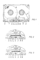
- the tape head is swung out, so that the magnetic tape itself is only on the tape guide elements on the front of the cassette, namely the rollers (6, 6 ⁇ ) and the webs (7, 7 ⁇ ) and the pins (8, 8 ⁇ ) is guided and should run freely past the central opening.
- unwanted contact of the magnetic tape with the pressure pad still occurs during rewinding, as a result of which the rewinding torque is increased and annoying noises can also occur.
- the reasons can be:
- the pressure spring is mounted on both sides of the front central opening between the tape guide pins (8, 8 ⁇ ) and the abutments (9, 9 ⁇ ).
- These abutments can be webs extending from the head chamber (FIG. 1) or, in other constructions, the bent ends of the shielding plate (FIG. 2) or molded pins (FIG. 3).
- the distance between tape guide pin and abutment must now have a minimum value of approximately 0.5 mm, as a result of which the pressure spring has a certain bearing play and can thus touch the magnetic tape via the pressure pad.
- the pressure pad which generally consists of a felt, must have a certain thickness due to the cassette specifications. Because of production tolerances in the thickness of the felt and the fact that hair can protrude from the felt, there are possibilities of contact with the tape when rewinding.
- the problem described is to be solved in that the magnetic tape is held in the passage openings for the sound head or the sound heads at a distance by spring arms, which are firmly connected to one another and held in the cassette housing by means of a joint which can be tilted are.
- the magnetic tape is placed on the spring arms by inserting the audio heads into the through-openings and held permanently by the magnetic heads, whereby different immersion depths of the audio heads are compensated for by swiveling the spring arms, while, for example, if there are no effective connections between the magnetic tape and the audio heads when rewinding the magnetic tape runs smoothly above the spring arms.
- the construction described is relatively complicated and therefore expensive to manufacture, so that it seems too expensive for a mass article like a compact cassette.
- the present invention had for its object to provide a magnetic tape cassette of the type mentioned, which avoids the disadvantage mentioned and is also easy to manufacture.
- the inventive idea consisted of pretensioning the pressure spring (4) in such a way that the bearing play mentioned above ceases to exist and the pressure cushion is shifted slightly towards the inside of the cassette, so that, as can be seen from FIG. 2, no tape contact with the cushion can occur during the rewinding process.
- This is achieved by directly adjacent to the tape guide pins (8, 8 ⁇ ) and the abutments (9, 9 ⁇ ), preferably in the direction of the central opening (2) of the front cassette part, two posts (11, 11 ⁇ ) so that the pressure spring (4) with the pillow (5) between the posts either lies flat or is slightly bent towards the shielding plate (10).
- the posts are molded onto the webs (12, 12 ⁇ ) of the base part (1), which cause the height of the pressure spring.
- the bearing elements (8, 8 ⁇ ), (9, 9 ⁇ ) and (11, 11 ⁇ ) can have an insertion bevel from above for easier insertion of the pressure spring, in that they are chamfered in the upper part.
- the front, the magnetic tape facing surfaces (13, 13 ⁇ ) of the post do not run parallel to the plane of the magnetic tape, but beveled trapezoidal towards the interior of the cassette, so that when the head is swung in there is no danger that the magnetic tape will rub against an edge of the post.
- the solution according to the invention has, in addition to the simple construction, the additional advantage that when the compact cassette is assembled, the pressure spring, since it is pretensioned, is firmly inserted in the base part after insertion and can therefore not fall out during the transport operations associated with the individual manufacturing steps.
Landscapes
- Packaging Of Annular Or Rod-Shaped Articles, Wearing Apparel, Cassettes, Or The Like (AREA)
Abstract
Description
- Die Erfindung betrifft eine Magnetbandcassette, insbesondere eine Compact-Cassette vom Philips-Typ, welche eine frontseitige Öffnung für den geräteseitigen Tonkopf sowie eine Einrichtung zum Andrücken des Magnetbandes an den Tonkopf besitzt.
- Bei einer Cassette dieses Typs, welche in Figur 1 dargestellt ist, greift zur Tonaufnahme und -wiedergabe der (nicht gezeichnete) Tonkopf durch die Öffnung (2) auf des Magnetband (3) hindurch, welches von der anderen Seite her durch eine Andruckfeder (4), die auf ihrer Vorderseite ein Kissen (5) trägt, an den Tonkopf gedrückt wird. Auf diese Weise wird ein enger Kontakt zwischen Tonkopf und Magnetband bewirkt. Zum Umspulen des Magnetbandes wird der Tonkopf ausgeschwenkt, so daß an sich das Magnetband lediglich über die an der Vorderseite der Cassette vorhandenen Bandführungselemente, nämlich die Röllchen (6, 6ʹ) und die Stege (7, 7ʹ) sowie die Stifte (8, 8ʹ) geführt wird und frei an der mittleren Öffnung vorbeilaufen sollte. Jedoch tritt in vielen Fällen beim Umspulen noch ein unerwünschter Kontakt des Magnetbandes mit dem Andruckkissen auf, wodurch das Umspuldrehmoment erhöht wird und außerdem lästige Geräusche auftreten können. Die Gründe können folgende sein:
- - Die Andruckfeder ist bei den meisten Compact-Cassetten beiderseits der frontseitigen mittleren Öffnung zwischen den Bandführungsstiften (8, 8ʹ) und den Widerlagern (9, 9ʹ) gelagert. Diese Widerlager können von der Kopfkammer ausgehende Stege (Figur 1) oder bei anderen Konstruktionen die umgebogenen Enden des Abschirmbleches sein (Figur 2) oder angespritzte Stifte (Figur 3) sein. Aus spritztechnischen Gründen muß nun der Abstand Bandführungsstifte-Widerlager einen Mindestwert von etwa 0,5 mm besitzen, wodurch die Andruckfeder ein gewisses Lagerspiel hat und auf diese Weise über das Andruckkissen das Magnetband berühren kann.
- - Das Andruckkissen, welches im allgemeinen aus einem Filz besteht, muß aufgrund der Cassettenspezifikationen eine bestimmte Dicke besitzen. Wegen Produktionstoleranzen in der Dicke des Filzes und wegen der Tatsache, daß aus dem Filz Haare herausragen können, sind beim Umspulen Berührungsmöglichkeiten mit dem Band vorhanden.
- Nach der Lehre der DE-OS 22 16 769 soll das geschilderte Problem dadurch gelöst werden, indem das Magnetband in den Durchgriffsöffnungen für den Tonkopf oder die Tonköpfe durch Federarme im Abstand hinterfaßt ist, die miteinander fest verbunden und mittels eines gemeinsamen Gelenks kippbeweglich im Cassettengehäuse gehalten sind. Bei der so gebildeten Cassette wird durch Einschieben der Tonköpfe in die Durchgriffsöffnungen das Magnetband an die Federarme angelegt und durch diese permanent an den Tonköpfen gehalten, wobei unterschiedliche Eintauchtiefen der Tonköpfe durch Abschwenken der Federarme ausgeglichen werden, während bei fehlenden Wirkverbindungen zwischen Magnetband und Tonköpfen zum Beispiel beim Umspulen das Magnetband reibungsfrei oberhalb der Federarme läuft. Die geschilderte Konstruktion ist relativ kompliziert und daher kostspielig herzustellen, so daß sie für einen Massenartikel wie eine Compact-Cassette als zu aufwendig erscheint.
- Aus der DE-OS 28 35 459 ist ein federndes Abschirmelement für Magnetbandcassetten bekannt, das im entspannten Zustand bereits gekrümmt ist, jedoch besteht bei dieser Konstruktion der bereits oben genannte Nachteil des Lagerspiels und außerdem hat das federnde Element eine relativ komplizierte Materialzusammensetzung beziehungsweise einen komlizierten Aufbau.
- Der vorliegenden Erfindung lag die Aufgabe zugrunde, eine Magnetband-Cassette des eingangs genannten Typs zu schaffen, welche den genannten Nachteil vermeidet und zudem einfach herzustellen ist.
- Die Aufgabe wurde erfindungsgemäß gelöst mit einer Magnetband-Cassette mit den im kennzeichnenden Teil des Anspruchs 1 genannten Merkmalen. Nähere Einzelheiten gehen aus den Unteransprüchen, der Beschreibung und den Zeichnungen hervor.
- Die Erfindung wird nun anhand der Zeichnungen näher erläutert und zwar zeigt:
- Figur 1 eine Draufsicht auf eine dem Stand der Technik entsprechende Cassette
- Figur 2 und 3 vergrößerte Ausschnitte aus Figur 1 mit herkömmlichen Lagerungen der Andruckeinrichtung
- Figur 4 einen vergrößerten Ausschnitt der Vorderseite der Cassette mit einer besonders bevorzugten Ausführung der Erfindung.
- Die erfinderische Idee bestand darin, die Andruckfeder (4) so vorzuspannen, daß das oben erwähnte Lagerspiel wegfällt und das Andruckkissen geringfügig in Richtung Cassetteninneres verschoben wird, so daß, wie aus Figur 2 zu erkennen, beim Umspulvorgang keine Bandberührung mit dem Kissen vorkommen kann. Dies wird dadurch erreicht, indem unmittelbar benachbart zu den Bandführungsstiften (8, 8ʹ) und den Widerlagern (9, 9ʹ) vorzugsweise in Richtung der mittleren Öffnung (2) des vorderen Cassettenteils zwei Pfosten (11, 11ʹ) so angebracht sind, daß die Andruckfeder (4) mit dem Kissen (5) zwischen den Pfosten entweder plan liegt oder in Richtung zum Abschirmblech (10) geringfügig durchgebogen ist. In einer bevorzugten Ausführung sind die Pfosten auf den Stegen (12, 12ʹ) des Bodenteils (1), welche die Höhenführung der Andruckfeder bewirken, angespritzt. Dadurch ist nur eine unerhebliche Änderung des Spritzwerkzeugs für die Herstellung des Cassettenbodenteils notwendig.
- Die Lagerelemente (8, 8ʹ), (9, 9ʹ) und (11, 11ʹ) können zum leichteren Einsetzen der Andruckfeder von oben eine Einführschräge besitzen, indem sie im oberen Teil abgeschrägt sind.
- Bevorzugt verlaufen die vorderen, dem Magnetband zugekehrten Flächen (13, 13ʹ) der Pfosten nicht parallel zur Ebene des Magnetbandes, sondern trapezförmig nach dem Cassetteninnenraum hin abgeschrägt, so daß bei eingeschwenktem Tonkopf keine Gefahr besteht, daß das Magnetband an einer Kante der Pfosten scheuert.
- Die erfindungsgemäße Lösung hat außer der einfachen Konstruktion noch den zusätzlichen Vorteil, daß bei der Konfektionierung der Compact-Cassette die Andruckfeder, da sie vorgespannt ist, nach dem Einsetzen fest im Bodenteil steckt und dadurch nicht während der mit den einzelnen Fabrikationsschritten verbundenen Transportvorgänge herausfallen kann.
Claims (4)
Applications Claiming Priority (2)
| Application Number | Priority Date | Filing Date | Title |
|---|---|---|---|
| DE3626286 | 1986-08-02 | ||
| DE19863626286 DE3626286A1 (de) | 1986-08-02 | 1986-08-02 | Magnetbandcassette |
Publications (2)
| Publication Number | Publication Date |
|---|---|
| EP0255647A1 true EP0255647A1 (de) | 1988-02-10 |
| EP0255647B1 EP0255647B1 (de) | 1990-03-28 |
Family
ID=6306610
Family Applications (1)
| Application Number | Title | Priority Date | Filing Date |
|---|---|---|---|
| EP87110512A Expired - Lifetime EP0255647B1 (de) | 1986-08-02 | 1987-07-21 | Magnetbandcassette |
Country Status (3)
| Country | Link |
|---|---|
| EP (1) | EP0255647B1 (de) |
| JP (1) | JP2512487B2 (de) |
| DE (2) | DE3626286A1 (de) |
Cited By (2)
| Publication number | Priority date | Publication date | Assignee | Title |
|---|---|---|---|---|
| EP0613138A2 (de) * | 1993-02-17 | 1994-08-31 | Koninklijke Philips Electronics N.V. | Träger für Druck- und Bandführungselement einer Magnetbandkassette und Magnetbandkassette für solche Elemente |
| AT401833B (de) * | 1993-02-06 | 1996-12-27 | Basf Magnetics Gmbh | Andruckeinrichtung für bandförmige aufzeichnungsträger und kassette damit |
Families Citing this family (2)
| Publication number | Priority date | Publication date | Assignee | Title |
|---|---|---|---|---|
| JPH01162180U (de) * | 1988-05-02 | 1989-11-10 | ||
| AT398251B (de) * | 1992-10-27 | 1994-11-25 | Philips Nv | Kassette zum aufnehmen eines magnetbandes, die einen andruckteilträger enthält, und andruckteilträger für eine solche kassette |
Citations (5)
| Publication number | Priority date | Publication date | Assignee | Title |
|---|---|---|---|---|
| DE2148594A1 (de) * | 1970-10-08 | 1972-04-13 | Alan Beaumont | Magnetbandbehaelter,der eine direkte Betrachtung von Anzeigemarken ermoeglicht |
| DE2216769A1 (de) * | 1972-04-07 | 1973-10-18 | Leo Dr Steipe | Tonbandkassette |
| DE2835459A1 (de) * | 1978-08-12 | 1980-02-28 | Vacuumschmelze Gmbh | Federndes abschirmelement, insbesondere fuer magnetbandkassetten |
| DE3148352A1 (de) * | 1980-12-09 | 1982-10-21 | Sony Corp., Tokyo | "magnetbandkassette" |
| EP0096983A2 (de) * | 1982-06-15 | 1983-12-28 | Dictaphone Corporation | Bandkassette |
Family Cites Families (1)
| Publication number | Priority date | Publication date | Assignee | Title |
|---|---|---|---|---|
| JPS60142876U (ja) * | 1984-02-29 | 1985-09-21 | 日立マクセル株式会社 | テ−プカ−トリツジ |
-
1986
- 1986-08-02 DE DE19863626286 patent/DE3626286A1/de not_active Withdrawn
-
1987
- 1987-07-21 EP EP87110512A patent/EP0255647B1/de not_active Expired - Lifetime
- 1987-07-21 DE DE8787110512T patent/DE3762074D1/de not_active Expired - Lifetime
- 1987-07-31 JP JP62190521A patent/JP2512487B2/ja not_active Expired - Lifetime
Patent Citations (5)
| Publication number | Priority date | Publication date | Assignee | Title |
|---|---|---|---|---|
| DE2148594A1 (de) * | 1970-10-08 | 1972-04-13 | Alan Beaumont | Magnetbandbehaelter,der eine direkte Betrachtung von Anzeigemarken ermoeglicht |
| DE2216769A1 (de) * | 1972-04-07 | 1973-10-18 | Leo Dr Steipe | Tonbandkassette |
| DE2835459A1 (de) * | 1978-08-12 | 1980-02-28 | Vacuumschmelze Gmbh | Federndes abschirmelement, insbesondere fuer magnetbandkassetten |
| DE3148352A1 (de) * | 1980-12-09 | 1982-10-21 | Sony Corp., Tokyo | "magnetbandkassette" |
| EP0096983A2 (de) * | 1982-06-15 | 1983-12-28 | Dictaphone Corporation | Bandkassette |
Cited By (3)
| Publication number | Priority date | Publication date | Assignee | Title |
|---|---|---|---|---|
| AT401833B (de) * | 1993-02-06 | 1996-12-27 | Basf Magnetics Gmbh | Andruckeinrichtung für bandförmige aufzeichnungsträger und kassette damit |
| EP0613138A2 (de) * | 1993-02-17 | 1994-08-31 | Koninklijke Philips Electronics N.V. | Träger für Druck- und Bandführungselement einer Magnetbandkassette und Magnetbandkassette für solche Elemente |
| EP0613138A3 (en) * | 1993-02-17 | 1994-09-14 | Philips Nv | Magnetic-tape cassette comprising a pressure-member support and tape-guide-member support, and pressure-member support for such a cassette and tape-guide-member support for such a cassette. |
Also Published As
| Publication number | Publication date |
|---|---|
| DE3626286A1 (de) | 1988-02-11 |
| DE3762074D1 (de) | 1990-05-03 |
| EP0255647B1 (de) | 1990-03-28 |
| JPS6337875A (ja) | 1988-02-18 |
| JP2512487B2 (ja) | 1996-07-03 |
Similar Documents
| Publication | Publication Date | Title |
|---|---|---|
| DE3222712A1 (de) | Magnetplattenkassette, bestehend aus einem gehaeuse und einer drehbaren magnetischen platte | |
| DE3433705A1 (de) | Magnetbandcassette | |
| DE2636169C3 (de) | Magnetbandkassette | |
| DE3142831A1 (de) | Magnetbandkassette | |
| DE2730381A1 (de) | Bandkassette | |
| DE2930072C2 (de) | Führungsvorrichtung für ein Magnetband in einer Magnetbandkassette | |
| EP0255647B1 (de) | Magnetbandcassette | |
| DE2633287C2 (de) | Bandkassette mit zwei parallel zueinander verlaufenden Kassettenhälften | |
| DE2937556A1 (de) | Magnetbandkassette | |
| DE2837890C2 (de) | Videobandkassette | |
| DE2721460A1 (de) | Magnetbandkassette | |
| DE3532530A1 (de) | Bandkassette | |
| DE3633163A1 (de) | Magnetbandkassette sowie bandfuehrungsblock dafuer | |
| EP0272537B1 (de) | Magnetbandcassette | |
| EP0243877B1 (de) | Magnetbandkassette | |
| EP0312891B1 (de) | Magnetbandcassette | |
| DE3213621A1 (de) | Bandkassette und kassettenrecorder | |
| DE2930646C2 (de) | Magnetbandkassette | |
| DE3330038A1 (de) | Magnetbandkassette | |
| EP0347670B1 (de) | Magnetbandcassette | |
| DE3327487A1 (de) | Druckkissen-vorrichtung fuer eine magnetbandkassette | |
| DE3408366A1 (de) | Magnetbandkassette | |
| EP0255646B1 (de) | Magnetbandcassette | |
| DE69915856T2 (de) | Spulenfeder für magnetbandkassette und magnetbandkassette | |
| EP0215965A1 (de) | Magazin für Tonbandkassetten |
Legal Events
| Date | Code | Title | Description |
|---|---|---|---|
| PUAI | Public reference made under article 153(3) epc to a published international application that has entered the european phase |
Free format text: ORIGINAL CODE: 0009012 |
|
| 17P | Request for examination filed |
Effective date: 19870721 |
|
| AK | Designated contracting states |
Kind code of ref document: A1 Designated state(s): BE DE FR GB IT NL |
|
| 17Q | First examination report despatched |
Effective date: 19890904 |
|
| GRAA | (expected) grant |
Free format text: ORIGINAL CODE: 0009210 |
|
| AK | Designated contracting states |
Kind code of ref document: B1 Designated state(s): BE DE FR GB IT NL |
|
| ITF | It: translation for a ep patent filed |
Owner name: ING. C. GREGORJ S.P.A. |
|
| GBT | Gb: translation of ep patent filed (gb section 77(6)(a)/1977) | ||
| REF | Corresponds to: |
Ref document number: 3762074 Country of ref document: DE Date of ref document: 19900503 |
|
| ET | Fr: translation filed | ||
| PLBE | No opposition filed within time limit |
Free format text: ORIGINAL CODE: 0009261 |
|
| STAA | Information on the status of an ep patent application or granted ep patent |
Free format text: STATUS: NO OPPOSITION FILED WITHIN TIME LIMIT |
|
| 26N | No opposition filed | ||
| ITTA | It: last paid annual fee | ||
| ITPR | It: changes in ownership of a european patent |
Owner name: CESSIONE;BASF MAGNETICS GMBH |
|
| NLS | Nl: assignments of ep-patents |
Owner name: BASF MAGNETICS GMBH TE MANNHEIM, BONDSREPUBLIEK DU |
|
| REG | Reference to a national code |
Ref country code: FR Ref legal event code: TP |
|
| REG | Reference to a national code |
Ref country code: GB Ref legal event code: 732 |
|
| PGFP | Annual fee paid to national office [announced via postgrant information from national office to epo] |
Ref country code: FR Payment date: 19940624 Year of fee payment: 8 |
|
| PGFP | Annual fee paid to national office [announced via postgrant information from national office to epo] |
Ref country code: BE Payment date: 19940713 Year of fee payment: 8 |
|
| PGFP | Annual fee paid to national office [announced via postgrant information from national office to epo] |
Ref country code: GB Payment date: 19940715 Year of fee payment: 8 |
|
| PGFP | Annual fee paid to national office [announced via postgrant information from national office to epo] |
Ref country code: NL Payment date: 19940731 Year of fee payment: 8 |
|
| PG25 | Lapsed in a contracting state [announced via postgrant information from national office to epo] |
Ref country code: GB Effective date: 19950721 |
|
| PG25 | Lapsed in a contracting state [announced via postgrant information from national office to epo] |
Ref country code: BE Effective date: 19950731 |
|
| BERE | Be: lapsed |
Owner name: BASF MAGNETICS G.M.B.H. Effective date: 19950731 |
|
| PG25 | Lapsed in a contracting state [announced via postgrant information from national office to epo] |
Ref country code: NL Effective date: 19960201 |
|
| GBPC | Gb: european patent ceased through non-payment of renewal fee |
Effective date: 19950721 |
|
| NLV4 | Nl: lapsed or anulled due to non-payment of the annual fee |
Effective date: 19960201 |
|
| PG25 | Lapsed in a contracting state [announced via postgrant information from national office to epo] |
Ref country code: FR Effective date: 19960430 |
|
| REG | Reference to a national code |
Ref country code: FR Ref legal event code: ST |
|
| REG | Reference to a national code |
Ref country code: FR Ref legal event code: ST |
|
| REG | Reference to a national code |
Ref country code: FR Ref legal event code: ST |
|
| PGFP | Annual fee paid to national office [announced via postgrant information from national office to epo] |
Ref country code: DE Payment date: 20020711 Year of fee payment: 16 |
|
| PG25 | Lapsed in a contracting state [announced via postgrant information from national office to epo] |
Ref country code: DE Free format text: LAPSE BECAUSE OF NON-PAYMENT OF DUE FEES Effective date: 20040203 |
|
| PG25 | Lapsed in a contracting state [announced via postgrant information from national office to epo] |
Ref country code: IT Free format text: LAPSE BECAUSE OF NON-PAYMENT OF DUE FEES;WARNING: LAPSES OF ITALIAN PATENTS WITH EFFECTIVE DATE BEFORE 2007 MAY HAVE OCCURRED AT ANY TIME BEFORE 2007. THE CORRECT EFFECTIVE DATE MAY BE DIFFERENT FROM THE ONE RECORDED. Effective date: 20050721 |