EP0254173B2 - Rost für Zerkleinerungsmaschinen - Google Patents
Rost für Zerkleinerungsmaschinen Download PDFInfo
- Publication number
- EP0254173B2 EP0254173B2 EP87110072A EP87110072A EP0254173B2 EP 0254173 B2 EP0254173 B2 EP 0254173B2 EP 87110072 A EP87110072 A EP 87110072A EP 87110072 A EP87110072 A EP 87110072A EP 0254173 B2 EP0254173 B2 EP 0254173B2
- Authority
- EP
- European Patent Office
- Prior art keywords
- comminuting
- machine according
- grate
- die
- operating elements
- Prior art date
- Legal status (The legal status is an assumption and is not a legal conclusion. Google has not performed a legal analysis and makes no representation as to the accuracy of the status listed.)
- Expired - Lifetime
Links
- 239000000463 material Substances 0.000 claims description 25
- 239000002699 waste material Substances 0.000 claims description 4
- 230000000875 corresponding effect Effects 0.000 description 9
- 238000013461 design Methods 0.000 description 8
- 230000000694 effects Effects 0.000 description 8
- 239000010410 layer Substances 0.000 description 8
- 238000006073 displacement reaction Methods 0.000 description 6
- 238000012545 processing Methods 0.000 description 5
- 125000006850 spacer group Chemical group 0.000 description 4
- 238000011161 development Methods 0.000 description 3
- 229910000831 Steel Inorganic materials 0.000 description 2
- 230000008878 coupling Effects 0.000 description 2
- 238000010168 coupling process Methods 0.000 description 2
- 238000005859 coupling reaction Methods 0.000 description 2
- JEIPFZHSYJVQDO-UHFFFAOYSA-N iron(III) oxide Inorganic materials O=[Fe]O[Fe]=O JEIPFZHSYJVQDO-UHFFFAOYSA-N 0.000 description 2
- 239000002184 metal Substances 0.000 description 2
- 239000010959 steel Substances 0.000 description 2
- 230000006978 adaptation Effects 0.000 description 1
- 230000002730 additional effect Effects 0.000 description 1
- 238000005275 alloying Methods 0.000 description 1
- 238000007664 blowing Methods 0.000 description 1
- 238000006243 chemical reaction Methods 0.000 description 1
- 239000007795 chemical reaction product Substances 0.000 description 1
- 238000010276 construction Methods 0.000 description 1
- 238000001816 cooling Methods 0.000 description 1
- 238000005520 cutting process Methods 0.000 description 1
- 238000000227 grinding Methods 0.000 description 1
- 229910001338 liquidmetal Inorganic materials 0.000 description 1
- 238000012423 maintenance Methods 0.000 description 1
- 238000004519 manufacturing process Methods 0.000 description 1
- 238000003913 materials processing Methods 0.000 description 1
- 238000010309 melting process Methods 0.000 description 1
- 238000002156 mixing Methods 0.000 description 1
- 230000000149 penetrating effect Effects 0.000 description 1
- 238000002360 preparation method Methods 0.000 description 1
- 239000000047 product Substances 0.000 description 1
- 230000001850 reproductive effect Effects 0.000 description 1
- 239000003923 scrap metal Substances 0.000 description 1
- 239000002356 single layer Substances 0.000 description 1
- 239000002893 slag Substances 0.000 description 1
- 239000002916 wood waste Substances 0.000 description 1
Images


Classifications
-
- B—PERFORMING OPERATIONS; TRANSPORTING
- B02—CRUSHING, PULVERISING, OR DISINTEGRATING; PREPARATORY TREATMENT OF GRAIN FOR MILLING
- B02C—CRUSHING, PULVERISING, OR DISINTEGRATING IN GENERAL; MILLING GRAIN
- B02C13/00—Disintegrating by mills having rotary beater elements ; Hammer mills
- B02C13/26—Details
- B02C13/282—Shape or inner surface of mill-housings
- B02C13/284—Built-in screens
Definitions
- the invention relates to a comminution machine according to the preamble of patent claim 1.
- a crushing machine of the above type, but which is only intended for metal scrap, is described in DE-A-22 25 916.
- this known shredding machine the design in the area of the grate or the grate arranged in the outlet area exerts an indirect or direct influence on the shredding result.
- such machines are less well suited for the waste and valuable materials processing industries, because the specific requirements that are placed on the quality of the end product, for example with regard to different piece sizes or fineness levels and / or densities, can only be achieved by using different types of outlet grates with varying ones Grate openings are met, which would have to be exchanged for one another in accordance with the desired final reduction result.
- the invention has for its object to mechanize the conversion of the machine in a comminution machine of the type described above, for which the feed material is not intended to be limited to scrap metal, however, in order to avoid the disadvantages described above.
- FR-A-2 527 477 discloses a shredding machine which has only a single-layer grate.
- the active elements can also consist of adjustable layers with holes of different sizes, a different hole geometry also being possible.
- different hole geometries are understood in particular to mean both different geometrical configurations of the holes, such as round or square holes, and various hole arrangements.
- the relative setting of the active elements to one another is preferably achieved in that the layers forming the active elements are either pivotally or displaceably mounted relative to one another. This measure ensures particularly practical handling and time-saving control of the adjustment of the active elements with respect to one another without machine downtime and disassembly, it being advisable to provide a step-by-step adjustment with impact.
- the invention and the device according to the invention offer the possibility, in the view of the operating personnel, of inserting or removing the comminution element required for the preparation of the particular material being driven during operation of the machine.
- easily crushable bark is fed to the device according to the invention, which does not require any special measures for shredding; in the meantime, stronger branches and roots can be abandoned that cannot be easily shredded.
- the operating personnel can immediately switch the machine according to the invention to the changed operating situation during operation by showing the patrix, which then protrudes through the die openings, so that the branches or roots given an additional crushing effect, whereby the Processing is significantly intensified.
- scrap processing industry is another possible area of application.
- refrigerated scrap high-density scrap, which is added towards the end of the melting process to calm and / or cool batches
- refrigerated scrap high-density scrap, which is added towards the end of the melting process to calm and / or cool batches
- Refrigerated scrap for the converter in blowing steel plants This scrap should have a density of at least 1.0 to 1.3 t / m 3 .
- Refrigerated scrap for the ladle which is fed in during the metallurgical finishing of the steel. This scrap must meet certain alloying requirements and be capable of being bunkered because it is fed in automatically operating metering and charging systems.
- the density should be 1.6 to 1.7 t / m 3 .
- Cooling scrap for the ladle This scrap must have a density of approx. 7.0 t / m 3 in order to be able to penetrate the liquid metal through the slag layer when the bath is calm.
- the dimensions should be approximately 15 to 20 mm in diameter and 100 mm in length.
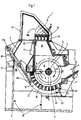
- the crushing machine generally designated 1, has a housing 2, which stands on a base plate 3.
- a zerklei runs in the housing 2 n réellesrotor 4 in the direction of rotation R, the shaft 5 is mounted on both sides in bearings, not shown, mounted on pedestals.
- the rotor 4 consists of several rotor disks 6 lined up at a distance from one another on the shaft 5, between which, in the exemplary embodiment shown in FIG. 1, only indicated cutting tools 7 are rotatably mounted on axes 8, which parallel the rotor disks 6 at a radial distance from the shaft 5 to enforce the latter.
- the shaft 5 is connected to a drive via a clutch disc (not shown).
- a good inlet 9 and good exits 10a and 10b are provided in the housing 2, a good inlet 9 and good exits 10a and 10b are provided.
- the material inlet 9 is arranged on the downward rotating side of the comminution rotor 4 at the level of the horizontal plane HH containing the rotor axis
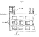
- the part of the housing 2 above the comminution rotor 4 is designed as an impact chute 12 open at the top and bottom, the height of which is approximately the diameter, for example the crushing rotor 4 corresponds to the top of the baffle 12 is covered with a grating or outlet grate 13 which is provided with grate openings 14 and extends perpendicular to the axis of the baffle 12.
- the classification or Outlet grate 13 can be closed by a cover plate 15 which is pivotably mounted about an axis 16 by means of hydraulic cylinders (not shown). By appropriately opening or closing the cover plate 15, it is also possible to influence the desired comminution result and the final density.
- a hood 17 is arranged above the classifying grate 13, on which the material thrown out of the grate openings when the flap 15 is open is deflected downward and then passes through an opening 18 to the outside. Any coarse parts which can be shredded and rotated in the housing 2 can be ejected through a flap 19 which can be pivoted about an axis 20 into the impact shaft 12.
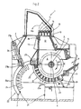
- the second outlet 10a which is also rust-like and is arranged downstream of the material inlet 9 in the direction of rotation R of the rotor 4, is designed according to the invention as follows:
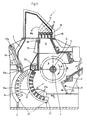
- the circular-shaped housing part (s) 21 containing the grate (s) 21 is or are in the exemplary embodiment shown in constructed in the radial direction from a plurality of layers forming active elements 22, the active elements 22 in the exemplary embodiment shown being designed as interlocking dies 23 and dies 24 and being displaceable or pivotable relative to one another.
- Preferred shapes or designs of matrices or patrices according to the invention are described in more detail below.
- gratings designed according to the invention can be arranged and provided at all points on the machine housing, e.g. in the housing base (as shown) as a cover for an outlet grate lying above the rotor or as a side outlet grate, for example in all spatial positions.
- the die 23 and the patrix 24 are mounted so as to be pivotable about a common pivot axis 25.
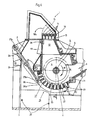
- Two hydraulic cylinders 26 - which are fastened on the one hand to the male part 24 and on the other hand to the housing 2 of the comminution machine 1 via articulated connections 27a and 27b - are used for opening, closing and / or blending, i.e. Penetrating or reaching through and pivoting the male 24 and / or female 23 into the various desired positions, each of which is required to adapt to the required piece size or fineness and / or density.
- corresponding coupling elements 28 for example a screw connection shown in FIGS.
- FIG. 1 the housing base 30 or the die 23 forms the housing part 21 of the comminution machine 1 which contains the grate.
- the male part 24 is in the pivoted-in state and engages in the die 23. In this way, a closed housing base 30 is created.
- the active elements 22, here die 23 and / or male 24, can be exchanged relatively easily with other active elements 22.
- the fastening elements 31 securing the swivel axis 25 and screwed to the die 23 and the fastening elements 32 by means of which the head 33 of the swivel axis 25 is fastened to the housing 2 are loosened. Then the pivot axis 25 can be pulled axially outwards to the recess 34 in the housing 2, so that the die 23 can be freely replaced downwards.
- the male part 24 is screwed onto a frame 24a, so that it can also be exchanged for any other male part at any time without great effort, for example only by loosening the fastening elements or the screws 35 shown in FIG. 11.
- FIG. 4 shows, for example, a position of the active elements 22 in which maintenance work on the comminution machine can be carried out particularly well and any material blockages can also be removed.
- the male part 36 is designed such that, as shown in FIG. 6, its protrusions extend or are pushed through the female part 37 and protrude beyond the inner surface 30 of the male part, then, for example, a grinding or tear tear occurs with certain materials, or in the case of scrap, for example, a so-called "mattress effect", which protects the housing base 30 against wear.
- the protrusions of the male part 36 are briefly pierced by the female part 37, the female part holes 37a could be cleaned and / or blockages removed from easily clogged materials.
- FIG. 7 shows an alternative die 39, in which the die holes 39a act as a stop due to a corresponding design - preferably an essentially L-shaped longitudinal section.
- a spacer 42 is arranged on a threaded bolt 40 which is guided through the male part 39 and is provided with a rotary lock 41.
- the spacer 42 is, as can be seen from Fig. 8, in the male frame 38a, arranged crosswise (see Fig.
- the spacer is countersunk in the lower elongated hole 43 by correspondingly rotating the screw cap 41 and thus the spacer 42, as a result of which the die 39 is lowered accordingly and the die 38 is pushed through through the die holes 39a, as shown in FIG. 9 .
- the die and patrix shown in the exemplary embodiments need not be made in one piece, but can be used within the scope of the invention e.g. can also be divided radially, that is to say formed in two parts, in order to enable the manipulation possibilities previously described in the one-piece construction with the arrangement of corresponding additional adjustment drives.
Landscapes
- Engineering & Computer Science (AREA)
- Food Science & Technology (AREA)
- Crushing And Pulverization Processes (AREA)
- Crushing And Grinding (AREA)
Applications Claiming Priority (2)
| Application Number | Priority Date | Filing Date | Title |
|---|---|---|---|
| DE19863624826 DE3624826A1 (de) | 1986-07-23 | 1986-07-23 | Rost fuer zerkleinerungsmaschinen |
| DE3624826 | 1986-07-23 |
Publications (4)
| Publication Number | Publication Date |
|---|---|
| EP0254173A2 EP0254173A2 (de) | 1988-01-27 |
| EP0254173A3 EP0254173A3 (en) | 1989-02-01 |
| EP0254173B1 EP0254173B1 (de) | 1991-04-03 |
| EP0254173B2 true EP0254173B2 (de) | 1994-08-10 |
Family
ID=6305750
Family Applications (1)
| Application Number | Title | Priority Date | Filing Date |
|---|---|---|---|
| EP87110072A Expired - Lifetime EP0254173B2 (de) | 1986-07-23 | 1987-07-13 | Rost für Zerkleinerungsmaschinen |
Country Status (6)
| Country | Link |
|---|---|
| US (2) | US4836457A (cg-RX-API-DMAC10.html) |
| EP (1) | EP0254173B2 (cg-RX-API-DMAC10.html) |
| JP (1) | JPS6336846A (cg-RX-API-DMAC10.html) |
| BR (1) | BR8703828A (cg-RX-API-DMAC10.html) |
| DE (2) | DE3624826A1 (cg-RX-API-DMAC10.html) |
| ES (2) | ES2013587T5 (cg-RX-API-DMAC10.html) |
Families Citing this family (70)
| Publication number | Priority date | Publication date | Assignee | Title |
|---|---|---|---|---|
| GB8722260D0 (en) * | 1987-09-22 | 1987-10-28 | Metpro Machinery | Hammermills |
| US5215269A (en) * | 1988-04-14 | 1993-06-01 | Alberto Pozzato | Armor plate for use in a hammer mill |
| FR2648057B1 (fr) * | 1989-06-13 | 1994-06-03 | Becker Arnaud | Procede de regulation de la densite de dechets metalliques broyes et dispositif pour la mise en oeuvre de ce procede |
| US5213273A (en) * | 1990-05-21 | 1993-05-25 | Lindemann Maschinenfabrik Gmbh | Hammer mill |
| DE4016295A1 (de) * | 1990-05-21 | 1991-11-28 | Lindemann Maschfab Gmbh | Hammerbrecher |
| US5178604A (en) * | 1990-05-31 | 1993-01-12 | Iovision, Inc. | Glaucoma implant |
| US5199653A (en) * | 1990-07-17 | 1993-04-06 | Garden Way Incorporated | Discharge assembly for chipper/shredder |
| US5244158A (en) * | 1990-08-02 | 1993-09-14 | Popovich Paul D | Scrap processor |
| DE4311435B4 (de) * | 1993-04-07 | 2005-10-06 | Werner Doppstadt | Zerkleinerungsmaschine mit Nachzerkleinerungskorb |
| DE4317287C2 (de) * | 1993-05-25 | 1997-02-27 | Thyssen Industrie | Zerkleinerungsvorrichtung für insbesondere Schrott |
| US5350120A (en) * | 1993-08-10 | 1994-09-27 | New England Redemption Of Connecticut, Inc. | Method of crushing a bottle and a glass crushing apparatus |
| DE19514951C2 (de) * | 1995-04-24 | 1998-02-19 | Willibald Gmbh Maschinenfabrik | Mobiler Abfall-Zerkleinerer |
| US5881959A (en) | 1995-05-04 | 1999-03-16 | Cmi Corporation | Materials grinder with infeed conveyor and anvil |
| US5863003A (en) | 1995-07-26 | 1999-01-26 | Smith; Leward M. | Waste processing machine |
| DE19547828A1 (de) * | 1995-12-21 | 1997-06-26 | Krupp Foerdertechnik Gmbh | Verfahren und Vorrichtung zur Einstellung der maximalen Körnung von gebrochenem oder gemahlenem Stückgut |
| DE19712587C2 (de) * | 1997-03-26 | 2001-11-15 | Svedala Lindemann Gmbh | Gehäuse für eine Zerkleinerungsmaschine |
| DE19715945A1 (de) * | 1997-04-16 | 1998-10-22 | Peter Wiedemann | Verfahren zum Entlacken von lackierten Substratteilen und Einrichtung zur Durchführung dieses Verfahrens |
| US5927622A (en) * | 1997-11-07 | 1999-07-27 | Eurohansa, Inc. | Waste grinder and bit therefore |
| US6047912A (en) * | 1998-05-01 | 2000-04-11 | Smith; Leward N. | Break-away processing tool for a waste processing machine |
| DE19835796C2 (de) * | 1998-08-07 | 2001-12-06 | Svedala Lindemann Gmbh | Verfahren zum Betreiben des Luftkreislaufes und Fördern des Gutstromes im Gehäuse eines Hammerbrechers und Gehäuse eines Hammerbrechers zur Durchführung des Verfahrens |
| US6032707A (en) * | 1998-12-22 | 2000-03-07 | Tramor, Inc. | Drum assembly for a wood chipper |
| US6036125A (en) * | 1998-12-22 | 2000-03-14 | Tramor, Inc. | Wood chipper |
| US6059210A (en) * | 1999-01-20 | 2000-05-09 | Smith; Leward N. | Rotor assembly for a waste processing machine |
| US6016855A (en) * | 1999-03-04 | 2000-01-25 | Tramor, Inc. | Hood assembly for a wood chipper |
| DE19925500A1 (de) * | 1999-06-04 | 2000-12-14 | Schaefer Elektrotechnik Sonder | Vorrichtung zum Verarbeiten von Bauteilen aus Mischstoffen |
| US6517020B1 (en) | 2000-09-08 | 2003-02-11 | Leward N. Smith | Replaceable raker assembly for processing tool of waste processing machine |
| US6357684B1 (en) | 2000-10-31 | 2002-03-19 | Tramor, Inc. | Adjustable tension feed wheel assembly for a wood chipper |
| US6591973B2 (en) | 2001-06-04 | 2003-07-15 | Leward N. Smith | Sideboard assembly for waste processing machine |
| US6729567B1 (en) | 2001-07-31 | 2004-05-04 | Tramor, Inc. | Side feed wheel assembly for wood chipper |
| US7384011B1 (en) | 2001-10-03 | 2008-06-10 | Leward Nile Smith | Multi-functional tool assembly for processing tool of waste processing machine |
| US7726594B2 (en) * | 2001-10-03 | 2010-06-01 | Leward Nile Smith | Multi-functional tool assembly for processing tool of material processing machine |
| US6845931B1 (en) | 2001-10-03 | 2005-01-25 | Leward Nile Smith | Multi-functional tool assembly for processing tool of waste processing machine |
| US6830204B1 (en) | 2001-12-10 | 2004-12-14 | Tramor, Inc. | Reversing automatic feed wheel assembly for wood chipper |
| US7007874B1 (en) | 2002-01-08 | 2006-03-07 | Leward Nile Smith | Shroud assembly for waste processing machine |
| US6804871B1 (en) | 2002-05-03 | 2004-10-19 | Leward Nile Smith | Method for aligning clutch assembly |
| US6955310B1 (en) | 2002-05-21 | 2005-10-18 | Tramor, Inc. | Remote control assembly for wood chipper |
| US6827304B2 (en) * | 2002-08-23 | 2004-12-07 | Victor Rousseau | Hay chopper for animal feed |
| US6843435B2 (en) * | 2002-11-18 | 2005-01-18 | Vermeer Manufacturing Company | Mill box for materials grinder |
| CA2507126A1 (en) * | 2002-11-26 | 2004-06-10 | Ambient Corporation | Arrangement of an inductive coupler for power line communications |
| US6955312B2 (en) * | 2002-12-20 | 2005-10-18 | Equipments Lan-Ro Inc. | Apparatus and method for comminuting rock |
| US7222805B1 (en) * | 2003-04-08 | 2007-05-29 | Williams Jr Robert M | Shredder with cage relief |
| US7090157B2 (en) * | 2004-03-19 | 2006-08-15 | Peterson Pacific Corp. | Material reducing apparatus |
| US7832670B2 (en) * | 2004-03-19 | 2010-11-16 | Astec Industries, Inc. | Material reducing apparatus |
| US7163166B1 (en) | 2004-03-31 | 2007-01-16 | Leward Nile Smith | Rotatable assembly for machines |
| US20070063080A1 (en) * | 2005-09-21 | 2007-03-22 | Evans Michael E | Adjustable screen for loose fill fibrous insulation machine |
| US8109303B1 (en) | 2006-04-27 | 2012-02-07 | Tramor, Inc. | Stump grinder having an automatic depth control system |
| US7942353B2 (en) * | 2006-10-26 | 2011-05-17 | Allegheny Paper Shredders Corporation | Adjustable screen for material destruction apparatus |
| US8092286B2 (en) * | 2007-05-23 | 2012-01-10 | Cnh America Llc | Concave pan portion of an integral chopper assembly of a combine harvester |
| WO2009143615A1 (en) * | 2008-05-27 | 2009-12-03 | Polycorp Ltd. | Discharge end liner |
| CA2732083C (en) * | 2008-08-01 | 2017-01-10 | Polycorp Ltd. | Unidirectional discharge grate assembly |
| US8353856B2 (en) | 2008-11-05 | 2013-01-15 | Abbott Medical Optics Inc. | Glaucoma drainage shunts and methods of use |
| USD651624S1 (en) * | 2009-02-20 | 2012-01-03 | Satake Corporation | Perforated hexagonal screen |
| EP2410959B1 (en) * | 2009-03-26 | 2014-06-11 | Abbott Medical Optics Inc. | Glaucoma shunts with flow management and improved surgical performance |
| CN102233290A (zh) * | 2011-05-01 | 2011-11-09 | 浙江黑白矿山机械有限公司 | 一种低进位全周角反击式破碎机 |
| CA2842482A1 (en) | 2011-07-21 | 2013-01-24 | Michael Boyd Morey | Safety device, backflow reduction device, conformable wood processing device, and methods thereof for a waste processing system |
| FI123525B (fi) * | 2012-01-30 | 2013-06-14 | Bmh Technology Oy | Murskain |
| JP2014073463A (ja) * | 2012-10-04 | 2014-04-24 | Miken:Kk | ハンマークラッシャー |
| CA2833700C (en) | 2012-11-22 | 2020-11-24 | Polycorp Ltd. | Discharge grate assembly |
| US9764329B2 (en) * | 2013-01-15 | 2017-09-19 | Aaron Engineered Process Equipment, Inc. | Rotary mill |
| WO2016010931A1 (en) | 2014-07-14 | 2016-01-21 | Esco Corporation | Discharge grates for reduction mills |
| DE202015003527U1 (de) * | 2014-12-19 | 2016-03-22 | Doppstadt Familienholding Gmbh | Zerkleinerungsvorrichtung mit einem Kammsystem |
| DE202018000803U1 (de) * | 2017-05-08 | 2018-08-09 | Doppstadt Familienholding Gmbh | Zerkleinerungsvorrichtung mit einem Kammsystem |
| DE102017006098B3 (de) * | 2017-06-28 | 2018-12-27 | Doppstadt Familienholding Gmbh | Zerkleinerungsvorrichtung |
| US10010028B1 (en) * | 2017-07-06 | 2018-07-03 | Cnh Industrial America Llc | Chopper assembly for a harvester with an automatic blade reset mechanism |
| US11672701B2 (en) | 2018-10-25 | 2023-06-13 | Amo Groningen B.V. | Bleb control glaucoma shunts |
| CN109909043A (zh) * | 2019-02-20 | 2019-06-21 | 北京昊华能源股份有限公司 | 一种高效的煤炭加工粉碎装置 |
| DE102019007192A1 (de) * | 2019-10-16 | 2021-04-22 | Siempelkamp Maschinen- Und Anlagenbau Gmbh | Vorrichtung zum Zerkleinern von schüttfähigem Aufgabegut sowie Verfahren zum Öffnen einer solchen Vorrichtung |
| DE102020102607A1 (de) * | 2020-02-03 | 2021-08-05 | Albert Hoffmann Gmbh | Hammermühle |
| DE102021118108B4 (de) | 2021-07-13 | 2024-09-05 | TSR Recycling GmbH & Co. KG | Verbessertes Verfahren zur Herstellung von Schrottprodukten mit hohem Reinheitsgrad aus inhomogenem Inputmaterial |
| EP4173716A1 (de) * | 2021-10-29 | 2023-05-03 | Comes Maschinen- und Apparatebau GmbH | Zerkleinerungsmaschine |
Family Cites Families (13)
| Publication number | Priority date | Publication date | Assignee | Title |
|---|---|---|---|---|
| US28368A (en) * | 1860-05-22 | Improvement in spade-plows | ||
| US1182575A (en) * | 1915-09-07 | 1916-05-09 | Saco Lowell Shops | Grid for pickers, openers, and allied machines. |
| US1523614A (en) * | 1922-07-14 | 1925-01-20 | Harry J Shelton | Grinder and shredder |
| US1634026A (en) * | 1926-10-12 | 1927-06-28 | Williem E Fritz | Feed cutter and grinder |
| US2440927A (en) * | 1945-03-23 | 1948-05-04 | Boss Floris | Adjustable two layered screen for hammer mills and remote control therefor |
| USRE28368E (en) | 1969-10-03 | 1975-03-18 | Grate bar assembly for a rock crusher | |
| DE2225916A1 (de) * | 1972-05-27 | 1973-12-13 | Lindemann Maschfab Gmbh | Verfahren zur gewinnung von metallschrott |
| US4226375A (en) * | 1978-12-21 | 1980-10-07 | Copper Alloys Corp. | Reduction mill |
| DE3147634C2 (de) * | 1981-12-02 | 1984-12-13 | Lindemann Maschinenfabrik Gmbh, 4000 Duesseldorf | Papierzerkleinerer und Verfahren zum Betrieb |
| FR2527477B1 (fr) | 1982-05-25 | 1988-05-20 | Mach Applic Environnement | Broyeur a marteaux a dispositif d'ejection perfectionne |
| DE3234298C2 (de) * | 1982-09-16 | 1985-12-19 | Lindemann Maschinenfabrik GmbH, 4000 Düsseldorf | Hammerbrecher |
| JPS59183836A (ja) * | 1983-04-05 | 1984-10-19 | 三菱重工業株式会社 | ハンマミル |
| DE3517579A1 (de) * | 1985-05-15 | 1986-11-20 | Thyssen Industrie Ag, 4300 Essen | Ausbildung des gehaeusebodens von zerkleinerungsmaschinen |
-
1986
- 1986-07-23 DE DE19863624826 patent/DE3624826A1/de active Granted
-
1987
- 1987-07-13 DE DE8787110072T patent/DE3769026D1/de not_active Expired - Lifetime
- 1987-07-13 ES ES87110072T patent/ES2013587T5/es not_active Expired - Lifetime
- 1987-07-13 EP EP87110072A patent/EP0254173B2/de not_active Expired - Lifetime
- 1987-07-13 ES ES87110072D patent/ES2013587A4/es active Pending
- 1987-07-22 US US07/076,278 patent/US4836457A/en not_active Expired - Fee Related
- 1987-07-22 JP JP62181264A patent/JPS6336846A/ja active Granted
- 1987-07-22 BR BR8703828A patent/BR8703828A/pt not_active IP Right Cessation
-
1989
- 1989-01-18 US US07/298,568 patent/US4982904A/en not_active Expired - Fee Related
Also Published As
| Publication number | Publication date |
|---|---|
| DE3624826C2 (cg-RX-API-DMAC10.html) | 1990-02-08 |
| BR8703828A (pt) | 1988-03-29 |
| EP0254173A2 (de) | 1988-01-27 |
| EP0254173A3 (en) | 1989-02-01 |
| ES2013587A4 (es) | 1990-05-16 |
| US4982904A (en) | 1991-01-08 |
| DE3624826A1 (de) | 1988-02-04 |
| JPH0464745B2 (cg-RX-API-DMAC10.html) | 1992-10-15 |
| DE3769026D1 (de) | 1991-05-08 |
| JPS6336846A (ja) | 1988-02-17 |
| EP0254173B1 (de) | 1991-04-03 |
| US4836457A (en) | 1989-06-06 |
| ES2013587T5 (es) | 1995-08-16 |
| ES2013587B3 (es) | 1991-08-01 |
Similar Documents
| Publication | Publication Date | Title |
|---|---|---|
| EP0254173B2 (de) | Rost für Zerkleinerungsmaschinen | |
| EP0376011B1 (de) | Gehäuse für eine Schrott-Zerkleinerungsmaschine | |
| DE3234298C2 (de) | Hammerbrecher | |
| DE2516014B2 (de) | Zerkleinerungsmaschine fur Abfälle | |
| DE202006006802U1 (de) | Zerkleinerungsvorrichtung | |
| DE3821360C2 (cg-RX-API-DMAC10.html) | ||
| EP0203272B1 (de) | Zerkleinerungsmaschine mit umlaufendem Rotor | |
| DE69512122T2 (de) | Vertikale Prallmühle | |
| WO1998042443A1 (de) | Gehäuse für eine zerkleinerungsmaschine | |
| EP0717663A1 (de) | Vorrichtung zum zerkleinern von stahl- oder metallspänen | |
| DE2353907B2 (de) | Prallmuehle | |
| DE102007043687A1 (de) | Werkzeug für eine Zerkleinerungsvorrichtung für kompostierbares Abfallmaterial | |
| EP3791961B1 (de) | Prallmühle zur zerkleinerung von feststoffen | |
| DE29616319U1 (de) | Walzenbrecher | |
| DE3905682C2 (cg-RX-API-DMAC10.html) | ||
| EP4173716A1 (de) | Zerkleinerungsmaschine | |
| DE3232030A1 (de) | Zerkleinerungsvorrichtung, insbesondere glockenmuehle oder kegelbrecher | |
| DE2814778C3 (de) | Zerkleinerungsmaschine für Schüttgüter | |
| DE19718614C1 (de) | Zerkleinerungsmaschine für sperrige Gegenstände | |
| DE959701C (de) | Vorrichtung zum Zerkleinern und Verfeinern von Papierstoff | |
| DE3442133A1 (de) | Zentrifugalschlagbrecheinrichtung | |
| DE1931250C3 (de) | Vorrichtung an Mühlen zur Zerkleinerung von Müll und ähnlichem Abfall | |
| DE8813467U1 (de) | Prallbrecher | |
| CH634235A5 (en) | Comminution machine for bulk materials | |
| AT770U1 (de) | Gartenhäcksler |
Legal Events
| Date | Code | Title | Description |
|---|---|---|---|
| PUAI | Public reference made under article 153(3) epc to a published international application that has entered the european phase |
Free format text: ORIGINAL CODE: 0009012 |
|
| AK | Designated contracting states |
Kind code of ref document: A2 Designated state(s): BE CH DE ES FR GB LI NL |
|
| PUAL | Search report despatched |
Free format text: ORIGINAL CODE: 0009013 |
|
| AK | Designated contracting states |
Kind code of ref document: A3 Designated state(s): BE CH DE ES FR GB LI NL |
|
| 17P | Request for examination filed |
Effective date: 19890412 |
|
| 17Q | First examination report despatched |
Effective date: 19891026 |
|
| GBC | Gb: translation of claims filed (gb section 78(7)/1977) | ||
| TCNL | Nl: translation of patent claims filed | ||
| EL | Fr: translation of claims filed | ||
| GRAA | (expected) grant |
Free format text: ORIGINAL CODE: 0009210 |
|
| AK | Designated contracting states |
Kind code of ref document: B1 Designated state(s): BE CH DE ES FR GB LI NL |
|
| GBT | Gb: translation of ep patent filed (gb section 77(6)(a)/1977) | ||
| REF | Corresponds to: |
Ref document number: 3769026 Country of ref document: DE Date of ref document: 19910508 |
|
| ET | Fr: translation filed | ||
| PLBI | Opposition filed |
Free format text: ORIGINAL CODE: 0009260 |
|
| 26 | Opposition filed |
Opponent name: METPRO MACHINERY LIMITED Effective date: 19920102 |
|
| NLR1 | Nl: opposition has been filed with the epo |
Opponent name: METPRO MACHINERY LIMITED |
|
| PUAA | Information related to the publication of a b2 document modified |
Free format text: ORIGINAL CODE: 0009299PMAP |
|
| PUAH | Patent maintained in amended form |
Free format text: ORIGINAL CODE: 0009272 |
|
| STAA | Information on the status of an ep patent application or granted ep patent |
Free format text: STATUS: PATENT MAINTAINED AS AMENDED |
|
| PGFP | Annual fee paid to national office [announced via postgrant information from national office to epo] |
Ref country code: ES Payment date: 19940729 Year of fee payment: 8 |
|
| 27A | Patent maintained in amended form |
Effective date: 19940810 |
|
| AK | Designated contracting states |
Kind code of ref document: B2 Designated state(s): NL |
|
| REG | Reference to a national code |
Ref country code: CH Ref legal event code: AEN |
|
| GBTA | Gb: translation of amended ep patent filed (gb section 77(6)(b)/1977) |
Effective date: 19940817 |
|
| NLR2 | Nl: decision of opposition | ||
| R27A | Patent maintained in amended form (corrected) |
Effective date: 19940810 |
|
| ET3 | Fr: translation filed ** decision concerning opposition | ||
| NLR3 | Nl: receipt of modified translations in the netherlands language after an opposition procedure | ||
| PGFP | Annual fee paid to national office [announced via postgrant information from national office to epo] |
Ref country code: GB Payment date: 19950622 Year of fee payment: 9 |
|
| PGFP | Annual fee paid to national office [announced via postgrant information from national office to epo] |
Ref country code: FR Payment date: 19950717 Year of fee payment: 9 |
|
| PGFP | Annual fee paid to national office [announced via postgrant information from national office to epo] |
Ref country code: CH Payment date: 19950719 Year of fee payment: 9 |
|
| PGFP | Annual fee paid to national office [announced via postgrant information from national office to epo] |
Ref country code: NL Payment date: 19950721 Year of fee payment: 9 |
|
| PGFP | Annual fee paid to national office [announced via postgrant information from national office to epo] |
Ref country code: BE Payment date: 19950809 Year of fee payment: 9 |
|
| REG | Reference to a national code |
Ref country code: ES Ref legal event code: DC2A Kind code of ref document: T5 Effective date: 19950816 |
|
| PGFP | Annual fee paid to national office [announced via postgrant information from national office to epo] |
Ref country code: DE Payment date: 19950925 Year of fee payment: 9 |
|
| PG25 | Lapsed in a contracting state [announced via postgrant information from national office to epo] |
Ref country code: GB Effective date: 19960713 |
|
| PG25 | Lapsed in a contracting state [announced via postgrant information from national office to epo] |
Ref country code: ES Free format text: LAPSE BECAUSE OF EXPIRATION OF PROTECTION Effective date: 19960715 |
|
| PG25 | Lapsed in a contracting state [announced via postgrant information from national office to epo] |
Ref country code: LI Effective date: 19960731 Ref country code: CH Effective date: 19960731 Ref country code: BE Effective date: 19960731 |
|
| BERE | Be: lapsed |
Owner name: LINDEMANN MASCHINENFABRIK G.M.B.H. Effective date: 19960731 |
|
| PG25 | Lapsed in a contracting state [announced via postgrant information from national office to epo] |
Ref country code: NL Effective date: 19970201 |
|
| GBPC | Gb: european patent ceased through non-payment of renewal fee |
Effective date: 19960713 |
|
| REG | Reference to a national code |
Ref country code: CH Ref legal event code: PL |
|
| PG25 | Lapsed in a contracting state [announced via postgrant information from national office to epo] |
Ref country code: FR Effective date: 19970328 |
|
| NLV4 | Nl: lapsed or anulled due to non-payment of the annual fee |
Effective date: 19970201 |
|
| PG25 | Lapsed in a contracting state [announced via postgrant information from national office to epo] |
Ref country code: DE Effective date: 19970501 |
|
| REG | Reference to a national code |
Ref country code: FR Ref legal event code: ST |
|
| REG | Reference to a national code |
Ref country code: ES Ref legal event code: FD2A Effective date: 19990601 |