EP0248700B1 - Verpackungsmaschine für "amerikanische" Schachteln - Google Patents
Verpackungsmaschine für "amerikanische" Schachteln Download PDFInfo
- Publication number
- EP0248700B1 EP0248700B1 EP87401109A EP87401109A EP0248700B1 EP 0248700 B1 EP0248700 B1 EP 0248700B1 EP 87401109 A EP87401109 A EP 87401109A EP 87401109 A EP87401109 A EP 87401109A EP 0248700 B1 EP0248700 B1 EP 0248700B1
- Authority
- EP
- European Patent Office
- Prior art keywords
- boxes
- borne
- machine according
- flaps
- box
- Prior art date
- Legal status (The legal status is an assumption and is not a legal conclusion. Google has not performed a legal analysis and makes no representation as to the accuracy of the status listed.)
- Expired - Lifetime
Links
Images


Classifications
-
- B—PERFORMING OPERATIONS; TRANSPORTING
- B65—CONVEYING; PACKING; STORING; HANDLING THIN OR FILAMENTARY MATERIAL
- B65B—MACHINES, APPARATUS OR DEVICES FOR, OR METHODS OF, PACKAGING ARTICLES OR MATERIALS; UNPACKING
- B65B59/00—Arrangements to enable machines to handle articles of different sizes, to produce packages of different sizes, to vary the contents of packages, to handle different types of packaging material, or to give access for cleaning or maintenance purposes
-
- B—PERFORMING OPERATIONS; TRANSPORTING
- B65—CONVEYING; PACKING; STORING; HANDLING THIN OR FILAMENTARY MATERIAL
- B65B—MACHINES, APPARATUS OR DEVICES FOR, OR METHODS OF, PACKAGING ARTICLES OR MATERIALS; UNPACKING
- B65B5/00—Packaging individual articles in containers or receptacles, e.g. bags, sacks, boxes, cartons, cans, jars
- B65B5/02—Machines characterised by incorporation of means for making the containers or receptacles
- B65B5/024—Machines characterised by incorporation of means for making the containers or receptacles for making containers from preformed blanks
-
- B—PERFORMING OPERATIONS; TRANSPORTING
- B65—CONVEYING; PACKING; STORING; HANDLING THIN OR FILAMENTARY MATERIAL
- B65B—MACHINES, APPARATUS OR DEVICES FOR, OR METHODS OF, PACKAGING ARTICLES OR MATERIALS; UNPACKING
- B65B5/00—Packaging individual articles in containers or receptacles, e.g. bags, sacks, boxes, cartons, cans, jars
- B65B5/06—Packaging groups of articles, the groups being treated as single articles
-
- B—PERFORMING OPERATIONS; TRANSPORTING
- B65—CONVEYING; PACKING; STORING; HANDLING THIN OR FILAMENTARY MATERIAL
- B65B—MACHINES, APPARATUS OR DEVICES FOR, OR METHODS OF, PACKAGING ARTICLES OR MATERIALS; UNPACKING
- B65B59/00—Arrangements to enable machines to handle articles of different sizes, to produce packages of different sizes, to vary the contents of packages, to handle different types of packaging material, or to give access for cleaning or maintenance purposes
- B65B59/003—Arrangements to enable adjustments related to the packaging material
-
- B—PERFORMING OPERATIONS; TRANSPORTING
- B65—CONVEYING; PACKING; STORING; HANDLING THIN OR FILAMENTARY MATERIAL
- B65B—MACHINES, APPARATUS OR DEVICES FOR, OR METHODS OF, PACKAGING ARTICLES OR MATERIALS; UNPACKING
- B65B7/00—Closing containers or receptacles after filling
- B65B7/16—Closing semi-rigid or rigid containers or receptacles not deformed by, or not taking-up shape of, contents, e.g. boxes or cartons
- B65B7/20—Closing semi-rigid or rigid containers or receptacles not deformed by, or not taking-up shape of, contents, e.g. boxes or cartons by folding-down preformed flaps
Definitions
- the invention relates to a case packing machine for American cases as defined in the first part of claim 1.
- components of a packaging machine be movable by means of adjustment screws coupled, one after the other, to mobile, portable drive means.
- Each component is successively brought back by the drive means to a reference position and then moved therefrom to the desired final position.
- the drive means are of the type constituted by a manually controlled engine block such as those used for electric hand tools (drill, sander, etc.).
- the structure of the envisaged adjustment means limits their use to a small number of means and to short strokes.
- This device requires effective access to the adjustment screws for coupling the drive means.
- the successive adjustment of the components lengthens the total adjustment time. In such a device, the settings are made independently of each other for the different components. Consequently, such a machine has crippling drawbacks if the format changes become more frequent and within a wider range and if the users seek to improve the productivity of the machine, by reducing downtime.
- the invention therefore aims to solve the problem of the flexibility of operation of American case packing machines according to the different formats of cases used and this without requiring on the part of the user a particular know-how or a waste of time. important.
- case packing machine for American cases is defined by the characteristics of claim 1.
- the case packing machine according to the invention has, over those of the state of the art, more particularly illustrated by documents US 2 280 773 and EP 0 142 007, the characteristic that the very structure of the machine is designed to allow the adjustment for the change of format, the adjustments of the various components of the machine being combined with each other and occurring essentially at least partially simultaneously with drive means forming an integral part of the machine, fixed as a whole and acting on the different organs simultaneously.
- the machine according to document EP 0 142 007 does not have a general structure specially adapted to an adjustment as contemplated by the invention and is satisfied, from a conventional machine structure, to make certain of its constituent parts, without combining the various adjustments between them, without incorporating the drive means into the machine.
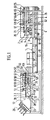
- the invention relates to a casing machine 1 for American boxes 2.
- An American box 2 is known per se and has four lateral faces 3, a bottom 4 and a cover 5.
- the bottom 4 and the cover 5 each consist of two first flaps 6, 7 respectively and two second flaps 8, 9 respectively .
- Two first flaps 6, 7 and two second flaps 8, 9 are contiguous to two opposite lateral faces 3 respectively
- the body 2 forms a flattened blank, the lateral faces 3 being folded one against the other and the flaps 6 , 7, 8, 9 free and located in the same plane as the side faces 3.
- the casing machine 1 is also intended for content 10 grouped in separate lots so as to be able to be cased in the various successive American cases placed in volume and opened.
- the casing machine 1 comprises, in the first place, means 11 for supplying empty boxes on which are placed from upstream to downstream on the one hand a store 12 of blanks of folded boxes stacked and on the other hand, means 13 for opening, for volume of the body 2 and for forming its bottom 4 by folding and securing the flaps 6, 8.
- the casing machine 1 comprises, secondly, means 14 for supplying the content 10 in batches suitable for being cased.
- the casing machine 1 comprises, thirdly, means 15 for transferring the batches of content 10 with a view to placing them in the open boxes 2 prepared for this purpose, interposed between the end portions downstream of the supply means 11 and supply means 14.
- the casing machine 1 comprises fourthly, means 16 for evacuating the boxes on which the transfer means 15 already mentioned are placed from upstream to downstream and means 17 for forming the cover 5 by folding and securing the flaps 7, 9 which constitute it.
- the upstream and downstream qualifiers are understood in relation to the direction of movement of the means of transport (supply or evacuation), namely the empty boxes for the supply means 11, the content packages 10 for the supply means 14 and the boxes 2 with the content lots 10 for the means of evacuation 16.
- the machine 1 is carried by a frame 18 resting on a generally horizontal support plane 19 (the ground), the supply means 11, 14 and discharge 16 extending generally horizontally.
- the discharge means 16 are placed substantially as an extension of the supply means 11 for empty boxes and the content supply means 14 are placed next to the discharge means 16, their direction of operation being opposite.
- the means 13 for opening, for volume of the body 2 and for constituting its bottom 4 as well as the means 17 for constituting the cover 5 are mounted sliding but lockable on axes and moved along these axes by means drive associated with digital control means not shown. These digital control means also control the other means of the machine.
- the machine 1 is generally designed, as a whole, to be adjustable, the axes on which are slidably but lockable mounted the members of the machine being integrated into the machine itself, rather than added to a known basic structure. These axes are arranged for the movements and the combined and at least partially simultaneous adjustments of the various members.
- the drive means are also integrated into the machine 1, fixed as a whole and at least partially common to the different axes or members. The axes and / or the drive means and / or the components of the machine are accessible or not, accessibility being not a determining condition for the adjustment.
- the drive means are preferably constituted by threaded rods driven in rotation by one or more motors.
- Other equivalent embodiments of the drive means can be envisaged (linear motors, jacks).
- at least some of the threaded rods extend transversely, right through the machine 1, carried by the frame 18, and comprise, at least for some of them, threads in opposite directions .
- the control means comprise manual means for displaying the format of the boxes 2 to be produced and filled and a programmable automaton associated with the manual display means and the drive means so that, depending on the setting of the manual means of display, the programmable controller controls the movement of the drive means until the means 13, 17 are brought into the positions corresponding to the chosen format.
- the various constituent bodies are thus adjusted automatically, in combination and at least partially simultaneously.
- the manual display means may consist of one or more mobile buttons in front of one or more dials on which the different possible formats are mentioned.
- the dials give the length, the width and the height of the boxes which can vary in particular and respectively between 150 and 450 mm, 100 and 300 mm, 190 and 500 mm.
- the adjustment of the machine by the display means can be continuous or discrete.
- the programmable controller can include the appropriate electronic elements such as memory, microprocessor, etc ...
- the means 15 for transferring the batches of content 10 are constituted by a robot with three degrees of freedom (one vertical axis and two horizontal axes) of so as to allow the boxes 2 to be filled with the content batches 10 either vertically or laterally. Consequently, the case-packing machine 1 according to the invention is versatile and, depending on the control of the transfer means 15, may be of the vertical cartoning or lateral cartoning type.
- the transfer means 15 (not shown in FIG. 1) comprise fixed support means 20 associated with the frame 18 and a plurality of arms 21 carried by the support means 20, moved by means of drive means such as jacks or motors, and terminated by gripping means 22 capable of gripping a batch of content 10.
- the gripping means 22 can be mechanical or pneumatic, in particular consisting of suction cups associated with a suction device.
- the gripping means 22 are constituted, for example, by a removable suction die head, comprising one or more lines and one or more rows of suction cups.
- the supply means 11 comprise support and guiding means associated with the frame 18 intended for movable cleats for driving the boxes 2 moved by means of drive means such as endless chains movable by one or more motors (not shown).
- the supply means 11, in particular the movable lugs for driving the boxes 2, define, for each box 2, a reference axis, in this case the lower horizontal edge upstream of the box 2.
- this reference axis can occupy several fixed reference positions along the supply means 11, namely a first initial upstream position 23, a second intermediate opening position 24, and a third final position for forming the bottom. 25.
- These positions 23, 24, 25 are preferably equidistant from each other.
- the adjustment of the means 13 for opening, setting in volume and constituting the bottom 4 is carried out with respect to the fixed positions 23, 24, 25.
- the magazine 12 is located to the right of the first position 23. It has several guide rails 26 suitable for keeping the blanks of folded boxes, superposed inclined, for example at approximately 45 ° relative to the supply means 11.
- the magazine 12 is, if necessary, adjustable to be adapted to the different formats of boxes or it is removable to be replaced by another magazine corresponding to another format or else there are several magazines placed side by side, each adapted to a format, these different magazines being mounted on drive means (such as threaded rod and motor) associated with the digital control means already mentioned.
- the magazine means 12 are preferably adjustable automatically by means of one or more axes controlled digitally.
- Means have the function of transferring the blanks from the magazine 12 to the supply means 11. They can be of the type with movable arm and suction cup driven by one or more motors, and by system crank or cam connecting rod.
- a horizontal and transverse axis 27 on which is pivotally mounted an arm 28 terminated by one or more suction cups 29 which can be applied to the side face 3 from above adjoining the reference axis, so as to allow the opening of the body 2.
- another movable suction cup is provided to be applied to the lateral face from below adjoining the reference axis.
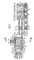
- the casing machine 1 also comprises at least two threaded rods 32, horizontal and transverse, comprising at their two end portions threads in opposite directions, cooperating with the threaded bearings 31 coaxial with the two longitudinal members 30. These threaded rods 32 are placed in below supply means 11 so as not to interfere with the boxes 2.
- Horizontal and transverse rolling bearings 33 of the threaded rods 32 are provided in the frame 18.
- At least one drive motor allows the drive in rotation and in synchronism of the threaded rods 32 by means of chains or the like 34 and therefore the displacement and the adjustment of the position of the side members 30.
- the longitudinal members 30 have, for example, in cross section, a square shape on a vertical branch of which are the bearings 31 and on the horizontal branch of which rest the members described below.
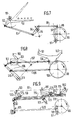
- the first spar (right spar in Figure 2 relative to the direction of advancement of the boxes 2) supports, from upstream to downstream, firstly, two arms 35, 36 extending in a horizontal plane pivoting around vertical axes 37, 38, having the function of folding the first two flaps 6 of the bottom 4 from the outside of the body 2.
- the first spar 30 supports, secondly, gluing means 39 placed horizontally and directed towards the vertical median plane of the machine 1. These sizing means 39 cooperate with the first flaps 6, folded, thanks to the arms 35, 36.
- the first spar 30 supports, thirdly, a vertical and longitudinal plate 40 by means of a cylinder 41, transverse. The plate 40 slides in transverse and horizontal direction and has the function of folding the second flaps 8 of the bottom 4, from the outside of the box 2.
- the second spar 30 (left spar in FIG. 2) supports, opposite the plate 40, mobile means 42 forming a counterpart on the first flaps 6 inside the body 2.
- the arms 35, 36 are movable between a retracted position (not shown) in which they are directed towards the outside of the machine and away from the supply means 11 and the boxes 2 and a working position where their respective support planes 43, 44 are coplanar in the plane of the bottom 4 ( Figure 2).
- This plane is also that in which the nozzle of the gluing means 35 and the plate 40 are located in a previous external position.
- the plate 40 is movable between two extreme positions, namely an anterior extreme working position already mentioned and an extreme posterior position, retracted, spaced from the bottom 4 and further away from the supply means 11.
- the upstream end portion of the support plane 43 of the upstream arm is located in or near the second reference position 24.
- the upstream end edge of the plate 40 is located, in turn, place or near the third reference position 25.
- the gluing means 39 are located slightly upstream of the plate 40, so as not to interfere with it.
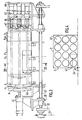
- the counterpart means 42 are constituted by a plurality of juxtaposed jacks 45 arranged in the form of a matrix comprising one or generally rows (FIG. 2) and one or generally columns (FIG. 3), the jacks 45 being carried by a vertical and longitudinal plate 46 spaced from the supply means 11 and rigidly associated with the second spar 30.
- Each of the jacks 45 has at the end of its rod an elementary counterpart plate 47.
- the jacks 45 are controlled by the control means already mentioned so that only part of the cylinders are active, namely those whose elementary counterpart plates 47 can penetrate into the body 2 concerned.
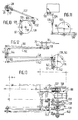
- the means 42 may comprise three rows and four columns of jacks 45 (FIG. 4).
- the number of rows and / or columns of cylinders 45 may be different and adapted to obtain the desired precision in the production of the different dimensions of different counterparts corresponding to the different formats of boxes envisaged.
- FIGS. 3 and 4 illustrate two possible extreme variants of box formats, the first, the largest, shown in plain lines and the second, the smallest, shown in broken lines. All of the jacks 45 are used for the first format while only one jack is used for the second format. The two beams 30 are respectively at their maximum spacing and at their minimum spacing for these two formats (the first and the second). The operation of the jacks 45 and the stroke of the jacks are controlled from the control means of the machine 1.
- a counterpart 42 in the form of a selectively controlled matrix allows the machine to be adapted to all box formats with particularly effective retention of the flaps from the inside, which ensures good attachment of the first and second flaps 4, 6 from the bottom 5.
- the jack matrix 45 is defined in dimensions by the largest box format to be treated.
- the cylinders 45 made active allow the displacement of the corresponding plates 47 between two extreme positions, namely a retracted position (FIG. 2 and solid lines in FIG. 3) away from the supply means 11 so as not to interfere with the body 2 and an active working position (dashed lines in FIG. 2 for the first variant of boxes) or the plates 47 are placed inside the box 2 bearing on the first flaps 6 and therefore practically in the same plane as the plate 40 .
- the simultaneous movement, over the same distance, but in the opposite direction, of the two beams 30 has the effect that the boxes 2 moving along the feed means 11 keep the same plane of reference namely the vertical median plane (of symmetry) of the machine.
- the reference plane would be, for example, the plane of the bottom 4.
- the feed means 11 with movable cleats comprise two sections in extension, namely a first upstream section extending between the first and second reference positions 23, 24 and a second downstream section extending between the second and third position 24, 25 to ensure the passage of the boxes 2 from the magazine 12 successively to each of these positions.
- the downstream section extends downstream to allow the exit of the boxes located on the supply means 11.
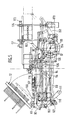
- the machine comprises at least two gantries 50, fixed, vertical and transverse, spanning the supply means 11, placed for example respectively between the second and third reference positions 24, 25 and downstream of the third position 25 respectively.
- the horizontal and transverse upper crosspieces 51 of the gantries 50 comprise vertical, median bearings 52 for guiding threaded rods 53.
- Drive bearings 54 are supported by the crosspieces 51 so as to be able to pivot around their vertical axes and include d on the one hand internal threads cooperating with the threaded rods 53 to ensure their sliding drive and on the other hand the teeth external training or similar.
- a chain or the like 55 drives the bearings 54 in synchronism through the teeth.
- a motor (not shown) drives the chains 55.
- the threaded rods 53 are placed vertically and in the middle.
- At the lower ends of the threaded rods 53 is fixed at least one spar (and preferably two spars slightly spaced from one another) 56, horizontal and upper, for example median, vertically movable but lockable in position adjustable by means control extending above the supply means 11, in particular between the second reference position 24 and the downstream end of the supply means 11.
- the beam 56 can be applied to the upper horizontal face of the open body 2 without preventing its sliding.
- Squaring means 57 of the body 2 are carried by the beam 56 in line with the vertical folding plate 40 and plates 47 forming a counterpart 42. This structure is therefore such that the plane of the feeding means 11 also constitutes a reference plane of the boxes 2, the squaring means 37 being moved to ensure their adjustment as a function of the format of the box 2 considered.
- the squaring means 57 comprise, on the one hand, an upstream pawl stop 58 for blocking the vertical transverse face upstream of the body 2 from above, being in the same plane as the third reference position 25 and, d 'other hand, a movable cleat 59 for biasing the vertical transverse face downstream of the body 2 from above and, upstream, carried by a chain 60 driven by a jack or the like 61 to an adjustable locking position thanks to automatic mechanical control means - such as a friction pinion - in which the body is kept perfectly square between the lower upstream cleat of the supply means 11 and the two upper cleats 58, 59.
- automatic mechanical control means - such as a friction pinion - in which the body is kept perfectly square between the lower upstream cleat of the supply means 11 and the two upper cleats 58, 59.
- the use of a friction pinion to the advantage of an automatic adjustment of the position of the cleat 59.
- the chain 60 and the jack 61 are placed above the beam 56 so as not to interfere with the open body 2.
- the cleat 58 forms a ratchet to allow the passage of the boxes 2 from upstream to downstream.
- the cleat 59 can be in a retracted rest position above the beam 56.
- the casing machine 1 may comprise, downstream of the supply means 11, means 48 for sliding and / or pivoting the box previously volume-set and opened by the means 13 in order to transfer it to the discharge means 16 so that the opening of the box is placed either laterally or on top, depending on whether the casing machine is of the side casing or vertical casing type.
- the supply means 14 for the content 10 can be in the form of a conveyor belt comprising transverse blocking bars 49 making it possible to drive and group the contents 10 into successive organized batches.
- the discharge means 16 also include one or more conveyor belts for driving the boxes 2, in particular filled, downstream.
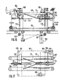
- the machine 1 comprises at least two gantries 62, fixed, vertical and transverse, spanning the evacuation means 16 and whose upper transverse 63 horizontal and transverse comprise guide bearings 64 for threaded rods 65 vertical.
- Drive bearings 66 are carried so as to be able to pivot about their vertical axes by the bearings 64 and comprise, on the one hand, threads cooperating with the threaded rods 65 to ensure their drive and, on the other hand, external drive teeth or the like.
- a chain or the like 67 driven by a motor (not shown) drives the bearings so that the threaded rods 65 are slidably synchronized.
- a spar 68 At the lower ends of the threaded rods 65 is fixed a spar 68, upper, median, movable vertically but lockable in position in an adjustable manner thanks to the digital control means, extending above the discharge means 16.
- This spar 68 supports d 'upstream downstream, firstly, an arm 69 pivoting about a horizontal and transverse axis 70 and driven by a jack 71 having the function of folding two first flaps 7 of the cover 5; secondly, gluing means 72 of the first flaps 7 previously folded; thirdly and in a fixed manner, two ramps 73, inclined up and down, and from upstream to downstream and from the outside to the inside, that is to say approaching one of the 'other while approaching the evacuation means 16 in the direction of advancement of the boxes 2 and having the function of folding the two second flaps 8 of the cover 5 during the advancement of the case 2 on the evacuation means 16; and, finally, fourthly, an endless belt 74 placed horizontally and longitudinally, applied to the second flaps 8 thus folded, that is to
- the arm 69 is movable between two extreme positions, namely, an inactive retracted position where it is placed horizontally in the upper part and away from the body 2 placed below and a working position where it is placed in the general direction vertical descending with its horizontal support plane 76. In this same horizontal plane are located the end of the gluing means 72 and the endless belt 74.
- the gluing means 72 are generally placed vertically and downwards. Between the arm 69 and the gluing means 72 is provided a support plate 77 inclined upstream and horizontal downstream under which the first flaps 7 can slide and whose function is to prevent these flaps 7 do not unfold after having escaped from the arm 69. This plate 77 is located immediately between the arm 69 and the gluing means 72.
- the endless strip 74 extends over a certain appropriate length, as a function of the speed of the strip and of the time required for bonding.
- the machine 1 also comprises two endless lateral belts 78 placed on either side of the discharge means 16, applied to the longitudinal lateral faces 3 of the boxes 2 and carried by mobile and adjustable longitudinal beams 79 and threaded rods 80 horizontal transverse and placed below the discharge means 16, these threaded rods 80 being driven in rotation by a motor and chains, so as to allow the endless belts 78 to move towards or away as a function of the body 2 considered.
- the supply means 12 are adjustable.
- the rails 26 are carried perpendicularly by two arms 81 inclined at approximately 45 ° on the horizontal, from upstream to downstream and from bottom to top, themselves carried by two support pieces 82 extending longitudinally. and laterally, with adjustable spacing, having, in vertical elevation a generally angular shape comprising a horizontal section and a vertical section, carried by two horizontal and transverse threaded rods respectively upstream and downstream 83 and 84 each with two opposite threads, cooperating respectively with tapped bearings of the support parts 82, respectively at the upstream end of the horizontal sections close to the association zone with the arms 81 and at the lower end of the vertical sections.
- the rails 26 of the magazine 12 are of adjustable spacing equally and concomitantly with the spacing of two longitudinal, lateral and horizontal slides 90 extending along the part of the machine 1 on which the body 2 is set in volume with its bottom 4 formed rigidly (before the means 48).
- These slides 90 have, in cross section, a square shape and they have the double function of constituting a support plane and a lateral guide of the boxes 2 or of blanks which constitute them.
- the means for transferring the blanks successively and to the unit of the magazine 12 up to the feeding means 11 are constituted, in this embodiment, by an arm 91, longitudinal, median placed between the slides 90 ( or alternatively several arms side by side), axially wedged and freely rotating on the upstream threaded rod 83 forming a pivot axis.
- the arm 91 comprises, integrally, a link 92 at about 120 ° directed towards the rear and upstream when the arm 91 is at rest horizontally.
- the connecting rod 92 is articulated the end of a rod 93 itself articulated, at its other end at the end of a lever 94 mounted articulated in its central part, freely around the downstream threaded rod 84 and at l other end of which is articulated the end of a lever 96 pivotally mounted at its other end about a horizontal, transverse, fixed axis 97, placed at the bottom of the machine 1 substantially between the opening means of the body 2 and the means of final production of the bottom 4, that is to say between the positions 24, 25.
- the lever 96 comprises a lug or the like cooperating with a cam 98 mounted on an axis 99, horizontal transverse and fixed, also placed at the lower part of the machine 1, in particular downstream of the axis 97.
- the arm 91 comprises a plurality of suction cups. Where appropriate, means are provided for selectively actuating the suction cups close to the threaded rod 83 and, on the contrary, not actuating those distant from it depending on the format of the blank to be transferred.
- the arm 91 is movable between two positions: a horizontal position directed downstream and an inclined extraction position in correspondence with the magazine 12 in particular from upstream to downstream and from bottom to top at about 60 °.
- the supply means are, as indicated above, preferably of the movable cleat drive type. More specifically, three or three series of tabs are provided, namely a first cleat 100 between the upstream position 23 and the intermediate position 24, a second cleat 101 between the intermediate position 24 and the final position 25 and a third cleat 102 between the final position 25 and the area of the means 48, that is to say when the body 2 is constituted. Preferably, pairs of tabs 100, 101, 102 are provided close to the slides 90.
- the tab 100 is carried by a first carriage 103 and the tabs 101 and 102 by a second carriage 104.
- the carriages 103 and 104 are mounted to slide horizontal longitudinal by means of one or more generally of two running rails 105, horizontal and longitudinal on which roll and are guides of the rollers 106 of the carriages.
- a link 107 connects the two carriages 103,104 spaced from each other by a fixed distance to ensure their displacement in synchronism.
- the reciprocating sliding movement of the carriages 103, 104 upstream and downstream is ensured in particular by means of the link 107 and from a cam 108 mounted on the axis 99 driving a link 109 articulated, at its other end at the middle part of a lever 110 articulated, at its first end lower than a horizontal, transverse, lower fixed axis 111 of the machine 1, located approximately plumb with the magazine 12 and articulated, at its second end higher than a connecting rod reference 112 itself articulated to the carriage 103.
- the lever 110 is moved between two extreme positions each at about 45 ° on the horizontal, upstream and downstream respectively.
- the tabs 100, 101, 102 are themselves carried by bodies mounted articulated on the respective carriages 103 and 104 around axes 113, 114 and 115 respectively.
- a horizontal and longitudinal rail 116 below the axes 113, 114, 115 is a horizontal and longitudinal rail 116.
- the rail 116 is arranged sliding vertically by means of a suitable device such as a deformable parallelogram with links 117 driven by drive means such as a cam 118 wedged on the axis 99 driving, via a crank pin 119 articulated on axis 97, a rod 120 generally horizontal and longitudinal, articulated at its opposite end to several rods designated as a whole by 121 articulated between them and finally to the deformable parallelogram with rod 117.
- rollers 122 and 123 doors by links 124 and 125 respectively, articulated on the axes 113 and 114 respectively and rigidly associated with the bodies of the lugs 100 and 101 respectively.
- a return link 126 articulated to the two bodies of the lugs 101 and 102 so as to ensure their synchronous rotation and in opposite directions, the lugs 100 and 101 pivoting synchronously and in the same direction.
- the rail 116 is movable between two upper and lower extreme positions in which, respectively, the tabs 100, 101 and 102 are in the protruding active position and in the retracted inactive position, this with respect to the reference plane constituted by the slides 90. This arrangement allows the forward movement of the tabs 100, 101 and 102 downstream in the active position upon their return upstream in the inactive position.
- the tabs 100, 101, 102 are preferably in pairs and located laterally in order to better take the box 2 and are adjustable in transverse spacing so as to take the box rather towards its lateral edges, which improves the guidance.
- the cleats are mounted sliding axially along fluted shafts such as 195, by means of complementary fluted sleeves 196 cooperating with the shafts 195.
- With the sleeve 196 is rigidly associated a grooved roller 197 also mounted on and around the splined shaft 195.
- a longitudinal projection 198 forming a rail cooperates with the groove of the roller 197.
- This longitudinal projection 198 forming a rail is joined integrally and kinematically to the spar of one of the spars 30.
- the fluted shafts 195 are carried so as to be pivoting. They are movable with transverse (relative to their axis) and longitudinal (relative to the machine) sliding.
- the projections forming the rails cause the axial sliding of the sleeves 196 and therefore the transverse adjustment of the cleats.
- the arm 28 carrying the suction cup 29 for opening the box 2 is driven by a link 127 which is articulated thereto and which is controlled by a cam 128 fixed on the axis 99.
- the cam 128 drives via a lug or similar a crank pin 129 articulated on the axis 97 at its lower end and to which is articulated, at its upper end a rod 130 generally horizontal and longitudinal around an axis 132 and to which is articulated the rod 127.
- This arrangement is such that the arm 28 can pivot 90 ° between two extreme positions respectively horizontal directed downstream and vertical upward.
- suction cups 133 intended to be applied to and maintain the lower horizontal lateral face of the body 2 when it is opened for the volume setting.
- This or these suction cups 133 are with vertical axis and carried, directly or not, by an arm 134 generally vertical and guided by guide means such as a sheath 135, controlled by vertical sliding by a rod 136 itself controlled by a cam 137 fixed on the axis 99, the connecting rod 136 being moreover articulated around a transverse, lower, fixed horizontal axis 138 located approximately below and vertically in line with the third final position 25.
- This structure allows the or the suction cups 133 are movable between an active upper working position and a retracted inactive lower position.
- the arms 35, 36 are also driven around their axes 37, 38 from two cams 139, 140 respectively fixed on the axis 99, by means of an appropriate linkage, it being emphasized that the axes 37 and 38 are vertical and the transverse horizontal axis 99.
- the cam 139 controls a crank pin 141 mounted articulated on the axis 97, on which is articulated a connecting rod 142, at one end, which generally horizontal connecting rod 142 is articulated, at its other end at the end of a lever 143 articulated in its median part around a horizontal and transverse axis 144 located at least substantially in line with the magazine 12, the lever 143 is articulated at its other end to a connecting rod 145 articulated to a connecting rod 146 of a single part with the arm 35 and therefore pivotally mounted around the axis 37.
- the connecting rod 145 is articulated with the lever 143 around a horizontal axis and with the connecting rod 146 around a vertical axis.
- crankpin 147 crankpin 147
- connecting rod 148 lever 149
- connecting rod 150 connecting rod 150
- connecting rod 151 connecting rod 151
- connecting rod 151 connecting rod 151
- a single motor 153 with geared motor and angle gear, placed in the lower part of the jaw, carried by the frame 18, in particular substantially perpendicular to the final position 25 drives the axis 99 and therefore the cams 98, 108, 118, 128, 137, 139 and 140, the axis 99 is carried by bearings 154.
- the machine 1 comprises, instead of the plate 40 two bars 155 extending horizontally and longitudinally carried by two arms 156 (or pairs of arms) articulated around horizontal and longitudinal axes 157 in the same vertical plane and close to one another, the assembly 155, 156, 157 forming a sort of axially extended clamp opening and closing.
- the axes 157 are carried by a carriage 158 carried and mounted to slide vertically by means of two vertical threaded columns 159 cooperating with threads of the carriage 158, placed in the same longitudinal vertical plane.
- These two threaded columns 159 are themselves carried, at their lower parts by the corresponding spar 30 and, at their upper parts by a longitudinal and upper horizontal spacer 160 maintained at a fixed spacing by means of rods or the like 161, horizontal and transverse of another spacer 162 horizontal, longitudinal, upper, coplanar with the spacer 162 but on the opposite lateral side of the machine, which spacer 162 supports two vertical columns 163 placed opposite the threaded columns 159 but on the other lateral side of the machine.
- the columns 163 are, in turn, carried by one or more carriages 164, driven, rolling in the horizontal transverse direction, sliding and by means of rollers 165 on horizontal and transverse slides 166 fixedly carried by the frame 18.
- Two other threaded columns 167 near the columns 163 extend vertically carried between and by the carriage (s) 164 and the spacer 162. Toothed gears 168 wedged at the projecting upper ends of the threaded columns 159 and 167, connected by a chain without end 169 or any equivalent means associated with a motor 170, to which we will return later, allows synchronous drive and in the same direction of the threaded columns 159 and 167.
- On the threaded columns 167 is mounted a carriage 171 by suitable tappings, this carriage 171 being placed horizontally in the same plane but opposite the carriage 158.
- the carriage 171 supports the counterpart means 42.
- the two carriages 158, 171 are therefore moved synchronously and are horizontally and transversely at a constant distance from each other.
- one or more lower transverse horizontal rods 172 are provided to maintain this distance.
- Means such as jacks have the function of opening and closing the clamp 155, 156, 157.
- the counterpart means 42 are, in this embodiment constituted by a single line of jacks 45 arranged in a horizontal plane intended to come to be applied to the bottom of the body 2, from the inside, in its median zone, opposite and against the two arms 156 brought close to each other, the corresponding clamp being closed.
- the change in shape of the body 2 is taken into account for the jacks 45, only in the event of a change in horizontal length, the number of active jacks being adapted accordingly.
- the structure described above with the rods 161 and 172 has the consequence that the stroke of the jacks 45 is constant whatever the body format 2 (in transverse direction).
- the spar 56 of the machine is, in this embodiment, carried by an upper horizontal frame 173 mounted to slide vertically by means of four vertical threaded columns 174 of fixed axes carried by the frame 18 of the machine.
- These threaded columns 174 are arranged, in particular connected by sprockets, chains or the like to rotate in synchronism in the same direction.
- the threaded columns 174 are driven by the same motor 170 as the threaded columns 159 and 167, with, however, a reduction gear so that the sliding stroke of the frame 173 is twice that of the carriages 158 and 171 or that the stroke of the carriages 158 and 171 is half that of the frame 173.
- the motor 170 can be of vertical axis and housed at the lower part of the machine, fixed as a whole on its lateral edge and driving the threaded columns 159 and 167 via a toothed wheel 175 double that 176 driving the threaded columns 174, the toothed wheel 175 has a vertical fixed axis carried by the frame 18. Given the displacement of the threaded columns 159, there is provided between these and the shaft of the toothed wheel 175 a universal joint 177. As follows from the above description, concerning the principle embodiment, the side members 30 are mounted to slide horizontally ement and transversely, in opposite directions and in synchronism thanks to threaded rods 32 and a motor 178 and support the slides 90.
- the threaded columns 159 and 167 not only rotate half as fast as the threaded columns 174 but also the vertical axes of the threaded columns 159 and 167 are movable horizontally and transversely while the axes of the threaded columns 174 are fixed, hence the frame structure 173 of dimensions larger than that of the threaded columns 159 and 167 in their different positions.
- the clamp 155, 156, 157 occupies, in turn, a fixed transverse relative position relative to the corresponding spar 30 so as to be permanently in the same relative position relative to the bottom 4 of the body 2 whatever its format.
- the beam 68 is carried directly by four threaded columns 179 with vertical axes carried in the lower part by the frame 18.
- the threaded columns 179 are driven from a gear motor 180 by a chain 181 and toothed pigs 182.
- the arm 69 is driven by a geared motor 183 and a crank rod 184, instead of a jack.
- the support plate 77 extends downstream beyond the gluing means 72, as far as the middle part of the ramps 73.
- a single geared motor 185 carried by the frame of the machine, in a fixed position causes on the one hand, the endless belt 74 by means of a drum 186 of horizontal axis and, on the other hand by identical drums 187 of vertical axes, the endless side bands 78.
- the moto- reduction gear 185 is associated with the drum 186 by a sliding angle box 188 on a keyed shaft 189 and with the drums 187 by sliding cardan drives 190.
- rollers 191 are provided for lateral retention of the body at its upper part , of vertical axes carried by two longitudinal and horizontal supports themselves carried by transverse threaded rods 192 by bearings 193 carried by the beam 68.
- a gear motor 194 also carried by the beam 68 allows the driving of the threaded rods so the reg rollers 191.
Landscapes
- Engineering & Computer Science (AREA)
- Mechanical Engineering (AREA)
- Making Paper Articles (AREA)
- Supplying Of Containers To The Packaging Station (AREA)
- Separation By Low-Temperature Treatments (AREA)
- Refrigerator Housings (AREA)
- Light Sources And Details Of Projection-Printing Devices (AREA)
- Auxiliary Devices For And Details Of Packaging Control (AREA)
Claims (28)
Priority Applications (1)
| Application Number | Priority Date | Filing Date | Title |
|---|---|---|---|
| AT87401109T ATE60295T1 (de) | 1986-05-16 | 1987-05-15 | Verpackungsmaschine fuer ''amerikanische'' schachteln. |
Applications Claiming Priority (2)
| Application Number | Priority Date | Filing Date | Title |
|---|---|---|---|
| FR8607096A FR2598680B1 (fr) | 1986-05-16 | 1986-05-16 | Machine d'encaissage pour caisses americaines |
| FR8607096 | 1986-05-16 |
Publications (2)
| Publication Number | Publication Date |
|---|---|
| EP0248700A1 EP0248700A1 (de) | 1987-12-09 |
| EP0248700B1 true EP0248700B1 (de) | 1991-01-23 |
Family
ID=9335340
Family Applications (1)
| Application Number | Title | Priority Date | Filing Date |
|---|---|---|---|
| EP87401109A Expired - Lifetime EP0248700B1 (de) | 1986-05-16 | 1987-05-15 | Verpackungsmaschine für "amerikanische" Schachteln |
Country Status (6)
| Country | Link |
|---|---|
| US (1) | US4807428A (de) |
| EP (1) | EP0248700B1 (de) |
| AT (1) | ATE60295T1 (de) |
| CA (1) | CA1288678C (de) |
| DE (1) | DE3767569D1 (de) |
| FR (1) | FR2598680B1 (de) |
Families Citing this family (21)
| Publication number | Priority date | Publication date | Assignee | Title |
|---|---|---|---|---|
| IT1228719B (it) * | 1989-03-15 | 1991-07-03 | Augusto Marchetti | Macchina nastratrice per scatole parallelepipede di cartone con chiusura sui fianchi. |
| FR2652561B1 (fr) * | 1989-10-02 | 1992-04-10 | Vega Automation | Procede et dispositif pour constituer, fermer et solidariser reciproquement les rabats d'une caisse telle qu'une caisse americaine en carton. |
| US5704196A (en) * | 1995-09-21 | 1998-01-06 | Douglas Machine Limited Liability Company | High speed blank set-up apparatus and methods |
| US5700998A (en) * | 1995-10-31 | 1997-12-23 | Palti; Yoram | Drug coding and delivery system |
| IT1292804B1 (it) * | 1997-03-18 | 1999-02-11 | Ima Spa | Apparecchiatura per la timbratura, l'incisione, la scontornatura di confezioni blister ottenute da un nastro alveolato. |
| US7146784B1 (en) | 1998-01-16 | 2006-12-12 | Meadwestvaco Packaging Systems, Llc | Machine for packaging a plurality of articles in a carton, and method of forming a carton |
| US6080095A (en) * | 1999-03-31 | 2000-06-27 | Tien Heng Machinery Co., Ltd. | Carton-shaping machine |
| US6309335B1 (en) * | 1999-11-10 | 2001-10-30 | Delaware Capital Formation | Vertically displaced hopper for bliss machines |
| ITBO20050584A1 (it) * | 2005-09-28 | 2007-03-29 | Marchesini Group Spa | Metodo per il confezionamento di articoli in contenitori scatolari e macchina che attua tale metodo |
| US20070204567A1 (en) * | 2006-03-03 | 2007-09-06 | R.A. Jones & Co. Inc. | Top load cartoner |
| FR2907101B1 (fr) * | 2006-10-11 | 2009-01-16 | Sidel Participations | Dispositif de transfert d'ebauches de caisses en carton. |
| EP1980494A1 (de) * | 2007-04-13 | 2008-10-15 | Diseños Integrales del Embalaje, s.a. | Vorrichtung für die Anpassung der Höhe von Faltschachteln und Faltschachtel dafür |
| US8323165B2 (en) * | 2009-09-14 | 2012-12-04 | Thiele Technologies, Inc. | Method for forming a container |
| ES2795664T3 (es) | 2010-06-29 | 2020-11-24 | Packsize Llc | Optimización de producción de productos de embalaje |
| JP5351946B2 (ja) * | 2011-08-10 | 2013-11-27 | 株式会社安川電機 | 梱包装置 |
| AU343832S (en) * | 2012-06-26 | 2012-08-10 | Adelaide Control Eng Pty Ltd | A containerised automated drum packing module |
| CN103144788B (zh) * | 2013-03-19 | 2015-08-26 | 苏州雪诺机械制造有限公司 | 具有压箱机构的封箱机 |
| WO2016001057A1 (en) * | 2014-07-03 | 2016-01-07 | Gea Food Solutions Germany Gmbh | Packaging machine for packages with an l-board |
| US11505341B1 (en) * | 2018-10-05 | 2022-11-22 | Douglas Machine Inc. | Robotic case packer platform and packing method |
| WO2020169098A1 (zh) * | 2019-02-22 | 2020-08-27 | 青岛萨沃特机器人有限公司 | 封盒装置及包装机 |
| CN118418517B (zh) * | 2024-07-01 | 2024-10-18 | 厦门安妮企业有限公司 | 一种折盒设备 |
Family Cites Families (18)
| Publication number | Priority date | Publication date | Assignee | Title |
|---|---|---|---|---|
| BE505317A (de) * | ||||
| GB535347A (en) * | 1939-11-29 | 1941-04-07 | Alfred German Rose | Improvements in packaging apparatus |
| US2280773A (en) * | 1940-08-03 | 1942-04-28 | Jl Ferguson Co | Carton opening, folding, and positioning machine |
| DE871420C (de) * | 1941-06-22 | 1953-03-23 | Jagenberg Werke Ag | Verfahren und Maschine zum Herstellen, Fuellen und Verschliessen von Behaeltern |
| US3164938A (en) * | 1962-03-16 | 1965-01-12 | American Mach & Foundry | Wrapping machine |
| CH418956A (de) * | 1962-11-23 | 1966-08-15 | Kirsten Rolf | Maschine zum Kartonieren von Füllgut aller Art |
| FR2029300A5 (de) * | 1969-01-24 | 1970-10-16 | Savoye | |
| US3611884A (en) * | 1970-01-26 | 1971-10-12 | William J Hottendorf | Box making machine |
| US3885372A (en) * | 1974-06-07 | 1975-05-27 | Peres Electronic Machines Inc | Automatic random case sealer |
| DE2702481A1 (de) * | 1977-01-21 | 1978-07-27 | Ferrero Ohg | Vorrichtung zum einsetzen von pralinen oder dergleichen |
| DD129767B1 (de) * | 1977-02-07 | 1982-03-31 | Erhard Blechschmidt | Vorrichtung zum stapeln prismatischer packungen |
| US4163414A (en) * | 1977-02-23 | 1979-08-07 | Wayne Automation Corp. | Method of erecting flat folded cases |
| US4150523A (en) * | 1977-11-15 | 1979-04-24 | Wrapmatic S.P.A. | Automatic machine for packing products of parallelepiped shape, particularly reams of paper |
| US4233798A (en) * | 1979-07-30 | 1980-11-18 | Helding James R | Box closing machine |
| SE433590B (sv) * | 1980-06-25 | 1984-06-04 | Sundpacma Ab | Metod och anordning for hantering och uppresning av slitslador av stort format |
| CH650722A5 (fr) * | 1983-02-21 | 1985-08-15 | Bobst Sa | Machine pour confectionner des boites pliantes. |
| DE3339924A1 (de) * | 1983-11-04 | 1985-05-15 | Robert Bosch Gmbh, 7000 Stuttgart | Verpackungsmaschine |
| DE3417508A1 (de) * | 1984-05-11 | 1985-11-14 | Uwe 7024 Filderstadt Knuth | Kartoniervorrichtung |
-
1986
- 1986-05-16 FR FR8607096A patent/FR2598680B1/fr not_active Expired
-
1987
- 1987-05-14 US US07/049,472 patent/US4807428A/en not_active Expired - Fee Related
- 1987-05-15 EP EP87401109A patent/EP0248700B1/de not_active Expired - Lifetime
- 1987-05-15 AT AT87401109T patent/ATE60295T1/de not_active IP Right Cessation
- 1987-05-15 DE DE8787401109T patent/DE3767569D1/de not_active Expired - Lifetime
- 1987-05-15 CA CA000537280A patent/CA1288678C/fr not_active Expired - Lifetime
Also Published As
| Publication number | Publication date |
|---|---|
| FR2598680B1 (fr) | 1989-04-21 |
| CA1288678C (fr) | 1991-09-10 |
| US4807428A (en) | 1989-02-28 |
| EP0248700A1 (de) | 1987-12-09 |
| FR2598680A1 (fr) | 1987-11-20 |
| DE3767569D1 (de) | 1991-02-28 |
| ATE60295T1 (de) | 1991-02-15 |
Similar Documents
| Publication | Publication Date | Title |
|---|---|---|
| EP0248700B1 (de) | Verpackungsmaschine für "amerikanische" Schachteln | |
| EP0411981B1 (de) | Verfahren und Maschine zum Banderolieren einer palettisierten Ladung | |
| EP0666234B1 (de) | Stapel-, Trennungs- und Abführungsstation für blattförmiges Gut, das von einer Verarbeitungsmaschine abgegeben wird | |
| CA2004409C (fr) | Machine, notamment encartonneuse, pour mettre automatiquement un article, en particulier un flacon, dans un etui | |
| FR2490602A1 (fr) | Systeme convoyeur rassemblant | |
| EP0354873A1 (de) | Entpalettierer für Etikettenbündel | |
| WO2008047008A1 (fr) | Machine de façonnage d'ebauches de caisses en carton | |
| EP0092093B1 (de) | Verfahren und Vorrichtung zur Beförderung von ineinanderfügbaren Gusseisernen Rohren um diese Kopf bei Fuss zu drehen | |
| CH633761A5 (fr) | Dispositif pour empiler des objets plats, notamment des decoupes de boites pliantes. | |
| FR2907369A1 (fr) | Procede et installation pour la confection d'une caisse composite | |
| EP0983951A2 (de) | Korrigierende Vorrichtung mit Rollen oder Riemen zur seitlichen Ausrichtung, während der Verarbeitung, von Gegenständen, wie in einer Falt-Leimmaschine teilweise gefalteten Blättern oder Zuschnitten | |
| FR2544658A1 (fr) | Intallation pour produire des caisses en carton sous forme pliee | |
| FR2980463A1 (fr) | Machine d'emballage. | |
| FR2484979A1 (fr) | Procede et appareil d'assemblage de matiere en feuille, notamment pour alimenter en continu des imprimantes rapides | |
| FR2563494A1 (fr) | Machine d'emballage a files multiples | |
| CH429560A (fr) | Machine à emballer | |
| FR2597290A1 (fr) | Procede et appareil de fabrication de faisceaux de conducteurs | |
| EP0411982A1 (de) | Verfahren und Maschine zum schraubenförmigen Anlegen eines Filmbandes auf den vertikalen Seiten einer Palettenladung | |
| FR2511341A1 (fr) | Machine a fermer les rabats de caisses d'emballage | |
| FR2493805A1 (fr) | Procede et machine pour constituer, remplir, fermer un contenant de forme generale parallelepipedique a partir d'une forme aplatie | |
| FR2463080A1 (fr) | Dispositif de transport de profiles extrudes | |
| FR2550513A1 (fr) | Dispositif de transfert pour une machine a envelopper | |
| FR2765554A1 (fr) | Machine permettant d'ouvrir des boites en carton de maniere automatisee | |
| FR2696674A1 (fr) | Procédé pour réaliser et usiner des onglets parallèles sur les deux surfaces frontales de pièces de bois allongées et machine à profiler à deux bouts pour la mise en Óoeuvre de ce procédé. | |
| EP0359616B1 (de) | Maschine zum Verschliessen von Behältern |
Legal Events
| Date | Code | Title | Description |
|---|---|---|---|
| PUAI | Public reference made under article 153(3) epc to a published international application that has entered the european phase |
Free format text: ORIGINAL CODE: 0009012 |
|
| AK | Designated contracting states |
Kind code of ref document: A1 Designated state(s): AT BE CH DE ES FR GB GR IT LI LU NL SE |
|
| 17P | Request for examination filed |
Effective date: 19880411 |
|
| 17Q | First examination report despatched |
Effective date: 19890913 |
|
| GRAA | (expected) grant |
Free format text: ORIGINAL CODE: 0009210 |
|
| AK | Designated contracting states |
Kind code of ref document: B1 Designated state(s): AT BE CH DE ES FR GB GR IT LI LU NL SE |
|
| PG25 | Lapsed in a contracting state [announced via postgrant information from national office to epo] |
Ref country code: SE Effective date: 19910123 Ref country code: NL Effective date: 19910123 Ref country code: GR Free format text: LAPSE BECAUSE OF FAILURE TO SUBMIT A TRANSLATION OF THE DESCRIPTION OR TO PAY THE FEE WITHIN THE PRESCRIBED TIME-LIMIT Effective date: 19910123 Ref country code: AT Effective date: 19910123 |
|
| REF | Corresponds to: |
Ref document number: 60295 Country of ref document: AT Date of ref document: 19910215 Kind code of ref document: T |
|
| REF | Corresponds to: |
Ref document number: 3767569 Country of ref document: DE Date of ref document: 19910228 |
|
| ITF | It: translation for a ep patent filed | ||
| PG25 | Lapsed in a contracting state [announced via postgrant information from national office to epo] |
Ref country code: ES Free format text: LAPSE BECAUSE OF FAILURE TO SUBMIT A TRANSLATION OF THE DESCRIPTION OR TO PAY THE FEE WITHIN THE PRESCRIBED TIME-LIMIT Effective date: 19910504 |
|
| GBT | Gb: translation of ep patent filed (gb section 77(6)(a)/1977) | ||
| PG25 | Lapsed in a contracting state [announced via postgrant information from national office to epo] |
Ref country code: LU Free format text: LAPSE BECAUSE OF NON-PAYMENT OF DUE FEES Effective date: 19910531 Ref country code: LI Effective date: 19910531 Ref country code: CH Effective date: 19910531 |
|
| NLV1 | Nl: lapsed or annulled due to failure to fulfill the requirements of art. 29p and 29m of the patents act | ||
| PLBE | No opposition filed within time limit |
Free format text: ORIGINAL CODE: 0009261 |
|
| STAA | Information on the status of an ep patent application or granted ep patent |
Free format text: STATUS: NO OPPOSITION FILED WITHIN TIME LIMIT |
|
| 26N | No opposition filed | ||
| REG | Reference to a national code |
Ref country code: CH Ref legal event code: PL |
|
| PGFP | Annual fee paid to national office [announced via postgrant information from national office to epo] |
Ref country code: GB Payment date: 19920513 Year of fee payment: 6 |
|
| PGFP | Annual fee paid to national office [announced via postgrant information from national office to epo] |
Ref country code: FR Payment date: 19920526 Year of fee payment: 6 |
|
| PGFP | Annual fee paid to national office [announced via postgrant information from national office to epo] |
Ref country code: DE Payment date: 19920610 Year of fee payment: 6 |
|
| PGFP | Annual fee paid to national office [announced via postgrant information from national office to epo] |
Ref country code: BE Payment date: 19920626 Year of fee payment: 6 |
|
| PG25 | Lapsed in a contracting state [announced via postgrant information from national office to epo] |
Ref country code: GB Effective date: 19930515 |
|
| PG25 | Lapsed in a contracting state [announced via postgrant information from national office to epo] |
Ref country code: BE Effective date: 19930531 |
|
| BERE | Be: lapsed |
Owner name: VEGA AUTOMATION Effective date: 19930531 |
|
| GBPC | Gb: european patent ceased through non-payment of renewal fee |
Effective date: 19930515 |
|
| PG25 | Lapsed in a contracting state [announced via postgrant information from national office to epo] |
Ref country code: FR Effective date: 19940131 |
|
| PG25 | Lapsed in a contracting state [announced via postgrant information from national office to epo] |
Ref country code: DE Effective date: 19940201 |
|
| REG | Reference to a national code |
Ref country code: FR Ref legal event code: ST |
|
| PG25 | Lapsed in a contracting state [announced via postgrant information from national office to epo] |
Ref country code: IT Free format text: LAPSE BECAUSE OF NON-PAYMENT OF DUE FEES Effective date: 20050515 |