EP0248700B1 - Packaging machine for "american" boxes - Google Patents
Packaging machine for "american" boxes Download PDFInfo
- Publication number
- EP0248700B1 EP0248700B1 EP87401109A EP87401109A EP0248700B1 EP 0248700 B1 EP0248700 B1 EP 0248700B1 EP 87401109 A EP87401109 A EP 87401109A EP 87401109 A EP87401109 A EP 87401109A EP 0248700 B1 EP0248700 B1 EP 0248700B1
- Authority
- EP
- European Patent Office
- Prior art keywords
- boxes
- borne
- machine according
- flaps
- box
- Prior art date
- Legal status (The legal status is an assumption and is not a legal conclusion. Google has not performed a legal analysis and makes no representation as to the accuracy of the status listed.)
- Expired - Lifetime
Links
Images


Classifications
-
- B—PERFORMING OPERATIONS; TRANSPORTING
- B65—CONVEYING; PACKING; STORING; HANDLING THIN OR FILAMENTARY MATERIAL
- B65B—MACHINES, APPARATUS OR DEVICES FOR, OR METHODS OF, PACKAGING ARTICLES OR MATERIALS; UNPACKING
- B65B59/00—Arrangements to enable machines to handle articles of different sizes, to produce packages of different sizes, to vary the contents of packages, to handle different types of packaging material, or to give access for cleaning or maintenance purposes
-
- B—PERFORMING OPERATIONS; TRANSPORTING
- B65—CONVEYING; PACKING; STORING; HANDLING THIN OR FILAMENTARY MATERIAL
- B65B—MACHINES, APPARATUS OR DEVICES FOR, OR METHODS OF, PACKAGING ARTICLES OR MATERIALS; UNPACKING
- B65B5/00—Packaging individual articles in containers or receptacles, e.g. bags, sacks, boxes, cartons, cans, jars
- B65B5/02—Machines characterised by incorporation of means for making the containers or receptacles
- B65B5/024—Machines characterised by incorporation of means for making the containers or receptacles for making containers from preformed blanks
-
- B—PERFORMING OPERATIONS; TRANSPORTING
- B65—CONVEYING; PACKING; STORING; HANDLING THIN OR FILAMENTARY MATERIAL
- B65B—MACHINES, APPARATUS OR DEVICES FOR, OR METHODS OF, PACKAGING ARTICLES OR MATERIALS; UNPACKING
- B65B5/00—Packaging individual articles in containers or receptacles, e.g. bags, sacks, boxes, cartons, cans, jars
- B65B5/06—Packaging groups of articles, the groups being treated as single articles
-
- B—PERFORMING OPERATIONS; TRANSPORTING
- B65—CONVEYING; PACKING; STORING; HANDLING THIN OR FILAMENTARY MATERIAL
- B65B—MACHINES, APPARATUS OR DEVICES FOR, OR METHODS OF, PACKAGING ARTICLES OR MATERIALS; UNPACKING
- B65B59/00—Arrangements to enable machines to handle articles of different sizes, to produce packages of different sizes, to vary the contents of packages, to handle different types of packaging material, or to give access for cleaning or maintenance purposes
- B65B59/003—Arrangements to enable adjustments related to the packaging material
-
- B—PERFORMING OPERATIONS; TRANSPORTING
- B65—CONVEYING; PACKING; STORING; HANDLING THIN OR FILAMENTARY MATERIAL
- B65B—MACHINES, APPARATUS OR DEVICES FOR, OR METHODS OF, PACKAGING ARTICLES OR MATERIALS; UNPACKING
- B65B7/00—Closing containers or receptacles after filling
- B65B7/16—Closing semi-rigid or rigid containers or receptacles not deformed by, or not taking-up shape of, contents, e.g. boxes or cartons
- B65B7/20—Closing semi-rigid or rigid containers or receptacles not deformed by, or not taking-up shape of, contents, e.g. boxes or cartons by folding-down preformed flaps
Definitions
- the invention relates to a case packing machine for American cases as defined in the first part of claim 1.
- components of a packaging machine be movable by means of adjustment screws coupled, one after the other, to mobile, portable drive means.
- Each component is successively brought back by the drive means to a reference position and then moved therefrom to the desired final position.
- the drive means are of the type constituted by a manually controlled engine block such as those used for electric hand tools (drill, sander, etc.).
- the structure of the envisaged adjustment means limits their use to a small number of means and to short strokes.
- This device requires effective access to the adjustment screws for coupling the drive means.
- the successive adjustment of the components lengthens the total adjustment time. In such a device, the settings are made independently of each other for the different components. Consequently, such a machine has crippling drawbacks if the format changes become more frequent and within a wider range and if the users seek to improve the productivity of the machine, by reducing downtime.
- the invention therefore aims to solve the problem of the flexibility of operation of American case packing machines according to the different formats of cases used and this without requiring on the part of the user a particular know-how or a waste of time. important.
- case packing machine for American cases is defined by the characteristics of claim 1.
- the case packing machine according to the invention has, over those of the state of the art, more particularly illustrated by documents US 2 280 773 and EP 0 142 007, the characteristic that the very structure of the machine is designed to allow the adjustment for the change of format, the adjustments of the various components of the machine being combined with each other and occurring essentially at least partially simultaneously with drive means forming an integral part of the machine, fixed as a whole and acting on the different organs simultaneously.
- the machine according to document EP 0 142 007 does not have a general structure specially adapted to an adjustment as contemplated by the invention and is satisfied, from a conventional machine structure, to make certain of its constituent parts, without combining the various adjustments between them, without incorporating the drive means into the machine.
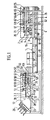
- the invention relates to a casing machine 1 for American boxes 2.
- An American box 2 is known per se and has four lateral faces 3, a bottom 4 and a cover 5.
- the bottom 4 and the cover 5 each consist of two first flaps 6, 7 respectively and two second flaps 8, 9 respectively .
- Two first flaps 6, 7 and two second flaps 8, 9 are contiguous to two opposite lateral faces 3 respectively
- the body 2 forms a flattened blank, the lateral faces 3 being folded one against the other and the flaps 6 , 7, 8, 9 free and located in the same plane as the side faces 3.
- the casing machine 1 is also intended for content 10 grouped in separate lots so as to be able to be cased in the various successive American cases placed in volume and opened.
- the casing machine 1 comprises, in the first place, means 11 for supplying empty boxes on which are placed from upstream to downstream on the one hand a store 12 of blanks of folded boxes stacked and on the other hand, means 13 for opening, for volume of the body 2 and for forming its bottom 4 by folding and securing the flaps 6, 8.
- the casing machine 1 comprises, secondly, means 14 for supplying the content 10 in batches suitable for being cased.
- the casing machine 1 comprises, thirdly, means 15 for transferring the batches of content 10 with a view to placing them in the open boxes 2 prepared for this purpose, interposed between the end portions downstream of the supply means 11 and supply means 14.
- the casing machine 1 comprises fourthly, means 16 for evacuating the boxes on which the transfer means 15 already mentioned are placed from upstream to downstream and means 17 for forming the cover 5 by folding and securing the flaps 7, 9 which constitute it.
- the upstream and downstream qualifiers are understood in relation to the direction of movement of the means of transport (supply or evacuation), namely the empty boxes for the supply means 11, the content packages 10 for the supply means 14 and the boxes 2 with the content lots 10 for the means of evacuation 16.
- the machine 1 is carried by a frame 18 resting on a generally horizontal support plane 19 (the ground), the supply means 11, 14 and discharge 16 extending generally horizontally.
- the discharge means 16 are placed substantially as an extension of the supply means 11 for empty boxes and the content supply means 14 are placed next to the discharge means 16, their direction of operation being opposite.
- the means 13 for opening, for volume of the body 2 and for constituting its bottom 4 as well as the means 17 for constituting the cover 5 are mounted sliding but lockable on axes and moved along these axes by means drive associated with digital control means not shown. These digital control means also control the other means of the machine.
- the machine 1 is generally designed, as a whole, to be adjustable, the axes on which are slidably but lockable mounted the members of the machine being integrated into the machine itself, rather than added to a known basic structure. These axes are arranged for the movements and the combined and at least partially simultaneous adjustments of the various members.
- the drive means are also integrated into the machine 1, fixed as a whole and at least partially common to the different axes or members. The axes and / or the drive means and / or the components of the machine are accessible or not, accessibility being not a determining condition for the adjustment.
- the drive means are preferably constituted by threaded rods driven in rotation by one or more motors.
- Other equivalent embodiments of the drive means can be envisaged (linear motors, jacks).
- at least some of the threaded rods extend transversely, right through the machine 1, carried by the frame 18, and comprise, at least for some of them, threads in opposite directions .
- the control means comprise manual means for displaying the format of the boxes 2 to be produced and filled and a programmable automaton associated with the manual display means and the drive means so that, depending on the setting of the manual means of display, the programmable controller controls the movement of the drive means until the means 13, 17 are brought into the positions corresponding to the chosen format.
- the various constituent bodies are thus adjusted automatically, in combination and at least partially simultaneously.
- the manual display means may consist of one or more mobile buttons in front of one or more dials on which the different possible formats are mentioned.
- the dials give the length, the width and the height of the boxes which can vary in particular and respectively between 150 and 450 mm, 100 and 300 mm, 190 and 500 mm.
- the adjustment of the machine by the display means can be continuous or discrete.
- the programmable controller can include the appropriate electronic elements such as memory, microprocessor, etc ...
- the means 15 for transferring the batches of content 10 are constituted by a robot with three degrees of freedom (one vertical axis and two horizontal axes) of so as to allow the boxes 2 to be filled with the content batches 10 either vertically or laterally. Consequently, the case-packing machine 1 according to the invention is versatile and, depending on the control of the transfer means 15, may be of the vertical cartoning or lateral cartoning type.
- the transfer means 15 (not shown in FIG. 1) comprise fixed support means 20 associated with the frame 18 and a plurality of arms 21 carried by the support means 20, moved by means of drive means such as jacks or motors, and terminated by gripping means 22 capable of gripping a batch of content 10.
- the gripping means 22 can be mechanical or pneumatic, in particular consisting of suction cups associated with a suction device.
- the gripping means 22 are constituted, for example, by a removable suction die head, comprising one or more lines and one or more rows of suction cups.
- the supply means 11 comprise support and guiding means associated with the frame 18 intended for movable cleats for driving the boxes 2 moved by means of drive means such as endless chains movable by one or more motors (not shown).
- the supply means 11, in particular the movable lugs for driving the boxes 2, define, for each box 2, a reference axis, in this case the lower horizontal edge upstream of the box 2.
- this reference axis can occupy several fixed reference positions along the supply means 11, namely a first initial upstream position 23, a second intermediate opening position 24, and a third final position for forming the bottom. 25.
- These positions 23, 24, 25 are preferably equidistant from each other.
- the adjustment of the means 13 for opening, setting in volume and constituting the bottom 4 is carried out with respect to the fixed positions 23, 24, 25.
- the magazine 12 is located to the right of the first position 23. It has several guide rails 26 suitable for keeping the blanks of folded boxes, superposed inclined, for example at approximately 45 ° relative to the supply means 11.
- the magazine 12 is, if necessary, adjustable to be adapted to the different formats of boxes or it is removable to be replaced by another magazine corresponding to another format or else there are several magazines placed side by side, each adapted to a format, these different magazines being mounted on drive means (such as threaded rod and motor) associated with the digital control means already mentioned.
- the magazine means 12 are preferably adjustable automatically by means of one or more axes controlled digitally.
- Means have the function of transferring the blanks from the magazine 12 to the supply means 11. They can be of the type with movable arm and suction cup driven by one or more motors, and by system crank or cam connecting rod.
- a horizontal and transverse axis 27 on which is pivotally mounted an arm 28 terminated by one or more suction cups 29 which can be applied to the side face 3 from above adjoining the reference axis, so as to allow the opening of the body 2.
- another movable suction cup is provided to be applied to the lateral face from below adjoining the reference axis.
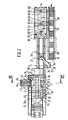
- the casing machine 1 also comprises at least two threaded rods 32, horizontal and transverse, comprising at their two end portions threads in opposite directions, cooperating with the threaded bearings 31 coaxial with the two longitudinal members 30. These threaded rods 32 are placed in below supply means 11 so as not to interfere with the boxes 2.
- Horizontal and transverse rolling bearings 33 of the threaded rods 32 are provided in the frame 18.
- At least one drive motor allows the drive in rotation and in synchronism of the threaded rods 32 by means of chains or the like 34 and therefore the displacement and the adjustment of the position of the side members 30.
- the longitudinal members 30 have, for example, in cross section, a square shape on a vertical branch of which are the bearings 31 and on the horizontal branch of which rest the members described below.
- the first spar (right spar in Figure 2 relative to the direction of advancement of the boxes 2) supports, from upstream to downstream, firstly, two arms 35, 36 extending in a horizontal plane pivoting around vertical axes 37, 38, having the function of folding the first two flaps 6 of the bottom 4 from the outside of the body 2.
- the first spar 30 supports, secondly, gluing means 39 placed horizontally and directed towards the vertical median plane of the machine 1. These sizing means 39 cooperate with the first flaps 6, folded, thanks to the arms 35, 36.
- the first spar 30 supports, thirdly, a vertical and longitudinal plate 40 by means of a cylinder 41, transverse. The plate 40 slides in transverse and horizontal direction and has the function of folding the second flaps 8 of the bottom 4, from the outside of the box 2.
- the second spar 30 (left spar in FIG. 2) supports, opposite the plate 40, mobile means 42 forming a counterpart on the first flaps 6 inside the body 2.
- the arms 35, 36 are movable between a retracted position (not shown) in which they are directed towards the outside of the machine and away from the supply means 11 and the boxes 2 and a working position where their respective support planes 43, 44 are coplanar in the plane of the bottom 4 ( Figure 2).
- This plane is also that in which the nozzle of the gluing means 35 and the plate 40 are located in a previous external position.
- the plate 40 is movable between two extreme positions, namely an anterior extreme working position already mentioned and an extreme posterior position, retracted, spaced from the bottom 4 and further away from the supply means 11.
- the upstream end portion of the support plane 43 of the upstream arm is located in or near the second reference position 24.
- the upstream end edge of the plate 40 is located, in turn, place or near the third reference position 25.
- the gluing means 39 are located slightly upstream of the plate 40, so as not to interfere with it.
- the counterpart means 42 are constituted by a plurality of juxtaposed jacks 45 arranged in the form of a matrix comprising one or generally rows (FIG. 2) and one or generally columns (FIG. 3), the jacks 45 being carried by a vertical and longitudinal plate 46 spaced from the supply means 11 and rigidly associated with the second spar 30.
- Each of the jacks 45 has at the end of its rod an elementary counterpart plate 47.
- the jacks 45 are controlled by the control means already mentioned so that only part of the cylinders are active, namely those whose elementary counterpart plates 47 can penetrate into the body 2 concerned.
- the means 42 may comprise three rows and four columns of jacks 45 (FIG. 4).
- the number of rows and / or columns of cylinders 45 may be different and adapted to obtain the desired precision in the production of the different dimensions of different counterparts corresponding to the different formats of boxes envisaged.
- FIGS. 3 and 4 illustrate two possible extreme variants of box formats, the first, the largest, shown in plain lines and the second, the smallest, shown in broken lines. All of the jacks 45 are used for the first format while only one jack is used for the second format. The two beams 30 are respectively at their maximum spacing and at their minimum spacing for these two formats (the first and the second). The operation of the jacks 45 and the stroke of the jacks are controlled from the control means of the machine 1.
- a counterpart 42 in the form of a selectively controlled matrix allows the machine to be adapted to all box formats with particularly effective retention of the flaps from the inside, which ensures good attachment of the first and second flaps 4, 6 from the bottom 5.
- the jack matrix 45 is defined in dimensions by the largest box format to be treated.
- the cylinders 45 made active allow the displacement of the corresponding plates 47 between two extreme positions, namely a retracted position (FIG. 2 and solid lines in FIG. 3) away from the supply means 11 so as not to interfere with the body 2 and an active working position (dashed lines in FIG. 2 for the first variant of boxes) or the plates 47 are placed inside the box 2 bearing on the first flaps 6 and therefore practically in the same plane as the plate 40 .
- the simultaneous movement, over the same distance, but in the opposite direction, of the two beams 30 has the effect that the boxes 2 moving along the feed means 11 keep the same plane of reference namely the vertical median plane (of symmetry) of the machine.
- the reference plane would be, for example, the plane of the bottom 4.
- the feed means 11 with movable cleats comprise two sections in extension, namely a first upstream section extending between the first and second reference positions 23, 24 and a second downstream section extending between the second and third position 24, 25 to ensure the passage of the boxes 2 from the magazine 12 successively to each of these positions.
- the downstream section extends downstream to allow the exit of the boxes located on the supply means 11.
- the machine comprises at least two gantries 50, fixed, vertical and transverse, spanning the supply means 11, placed for example respectively between the second and third reference positions 24, 25 and downstream of the third position 25 respectively.
- the horizontal and transverse upper crosspieces 51 of the gantries 50 comprise vertical, median bearings 52 for guiding threaded rods 53.
- Drive bearings 54 are supported by the crosspieces 51 so as to be able to pivot around their vertical axes and include d on the one hand internal threads cooperating with the threaded rods 53 to ensure their sliding drive and on the other hand the teeth external training or similar.
- a chain or the like 55 drives the bearings 54 in synchronism through the teeth.
- a motor (not shown) drives the chains 55.
- the threaded rods 53 are placed vertically and in the middle.
- At the lower ends of the threaded rods 53 is fixed at least one spar (and preferably two spars slightly spaced from one another) 56, horizontal and upper, for example median, vertically movable but lockable in position adjustable by means control extending above the supply means 11, in particular between the second reference position 24 and the downstream end of the supply means 11.
- the beam 56 can be applied to the upper horizontal face of the open body 2 without preventing its sliding.
- Squaring means 57 of the body 2 are carried by the beam 56 in line with the vertical folding plate 40 and plates 47 forming a counterpart 42. This structure is therefore such that the plane of the feeding means 11 also constitutes a reference plane of the boxes 2, the squaring means 37 being moved to ensure their adjustment as a function of the format of the box 2 considered.
- the squaring means 57 comprise, on the one hand, an upstream pawl stop 58 for blocking the vertical transverse face upstream of the body 2 from above, being in the same plane as the third reference position 25 and, d 'other hand, a movable cleat 59 for biasing the vertical transverse face downstream of the body 2 from above and, upstream, carried by a chain 60 driven by a jack or the like 61 to an adjustable locking position thanks to automatic mechanical control means - such as a friction pinion - in which the body is kept perfectly square between the lower upstream cleat of the supply means 11 and the two upper cleats 58, 59.
- automatic mechanical control means - such as a friction pinion - in which the body is kept perfectly square between the lower upstream cleat of the supply means 11 and the two upper cleats 58, 59.
- the use of a friction pinion to the advantage of an automatic adjustment of the position of the cleat 59.
- the chain 60 and the jack 61 are placed above the beam 56 so as not to interfere with the open body 2.
- the cleat 58 forms a ratchet to allow the passage of the boxes 2 from upstream to downstream.
- the cleat 59 can be in a retracted rest position above the beam 56.
- the casing machine 1 may comprise, downstream of the supply means 11, means 48 for sliding and / or pivoting the box previously volume-set and opened by the means 13 in order to transfer it to the discharge means 16 so that the opening of the box is placed either laterally or on top, depending on whether the casing machine is of the side casing or vertical casing type.
- the supply means 14 for the content 10 can be in the form of a conveyor belt comprising transverse blocking bars 49 making it possible to drive and group the contents 10 into successive organized batches.
- the discharge means 16 also include one or more conveyor belts for driving the boxes 2, in particular filled, downstream.
- the machine 1 comprises at least two gantries 62, fixed, vertical and transverse, spanning the evacuation means 16 and whose upper transverse 63 horizontal and transverse comprise guide bearings 64 for threaded rods 65 vertical.
- Drive bearings 66 are carried so as to be able to pivot about their vertical axes by the bearings 64 and comprise, on the one hand, threads cooperating with the threaded rods 65 to ensure their drive and, on the other hand, external drive teeth or the like.
- a chain or the like 67 driven by a motor (not shown) drives the bearings so that the threaded rods 65 are slidably synchronized.
- a spar 68 At the lower ends of the threaded rods 65 is fixed a spar 68, upper, median, movable vertically but lockable in position in an adjustable manner thanks to the digital control means, extending above the discharge means 16.
- This spar 68 supports d 'upstream downstream, firstly, an arm 69 pivoting about a horizontal and transverse axis 70 and driven by a jack 71 having the function of folding two first flaps 7 of the cover 5; secondly, gluing means 72 of the first flaps 7 previously folded; thirdly and in a fixed manner, two ramps 73, inclined up and down, and from upstream to downstream and from the outside to the inside, that is to say approaching one of the 'other while approaching the evacuation means 16 in the direction of advancement of the boxes 2 and having the function of folding the two second flaps 8 of the cover 5 during the advancement of the case 2 on the evacuation means 16; and, finally, fourthly, an endless belt 74 placed horizontally and longitudinally, applied to the second flaps 8 thus folded, that is to
- the arm 69 is movable between two extreme positions, namely, an inactive retracted position where it is placed horizontally in the upper part and away from the body 2 placed below and a working position where it is placed in the general direction vertical descending with its horizontal support plane 76. In this same horizontal plane are located the end of the gluing means 72 and the endless belt 74.
- the gluing means 72 are generally placed vertically and downwards. Between the arm 69 and the gluing means 72 is provided a support plate 77 inclined upstream and horizontal downstream under which the first flaps 7 can slide and whose function is to prevent these flaps 7 do not unfold after having escaped from the arm 69. This plate 77 is located immediately between the arm 69 and the gluing means 72.
- the endless strip 74 extends over a certain appropriate length, as a function of the speed of the strip and of the time required for bonding.
- the machine 1 also comprises two endless lateral belts 78 placed on either side of the discharge means 16, applied to the longitudinal lateral faces 3 of the boxes 2 and carried by mobile and adjustable longitudinal beams 79 and threaded rods 80 horizontal transverse and placed below the discharge means 16, these threaded rods 80 being driven in rotation by a motor and chains, so as to allow the endless belts 78 to move towards or away as a function of the body 2 considered.
- the supply means 12 are adjustable.
- the rails 26 are carried perpendicularly by two arms 81 inclined at approximately 45 ° on the horizontal, from upstream to downstream and from bottom to top, themselves carried by two support pieces 82 extending longitudinally. and laterally, with adjustable spacing, having, in vertical elevation a generally angular shape comprising a horizontal section and a vertical section, carried by two horizontal and transverse threaded rods respectively upstream and downstream 83 and 84 each with two opposite threads, cooperating respectively with tapped bearings of the support parts 82, respectively at the upstream end of the horizontal sections close to the association zone with the arms 81 and at the lower end of the vertical sections.
- the rails 26 of the magazine 12 are of adjustable spacing equally and concomitantly with the spacing of two longitudinal, lateral and horizontal slides 90 extending along the part of the machine 1 on which the body 2 is set in volume with its bottom 4 formed rigidly (before the means 48).
- These slides 90 have, in cross section, a square shape and they have the double function of constituting a support plane and a lateral guide of the boxes 2 or of blanks which constitute them.
- the means for transferring the blanks successively and to the unit of the magazine 12 up to the feeding means 11 are constituted, in this embodiment, by an arm 91, longitudinal, median placed between the slides 90 ( or alternatively several arms side by side), axially wedged and freely rotating on the upstream threaded rod 83 forming a pivot axis.
- the arm 91 comprises, integrally, a link 92 at about 120 ° directed towards the rear and upstream when the arm 91 is at rest horizontally.
- the connecting rod 92 is articulated the end of a rod 93 itself articulated, at its other end at the end of a lever 94 mounted articulated in its central part, freely around the downstream threaded rod 84 and at l other end of which is articulated the end of a lever 96 pivotally mounted at its other end about a horizontal, transverse, fixed axis 97, placed at the bottom of the machine 1 substantially between the opening means of the body 2 and the means of final production of the bottom 4, that is to say between the positions 24, 25.
- the lever 96 comprises a lug or the like cooperating with a cam 98 mounted on an axis 99, horizontal transverse and fixed, also placed at the lower part of the machine 1, in particular downstream of the axis 97.
- the arm 91 comprises a plurality of suction cups. Where appropriate, means are provided for selectively actuating the suction cups close to the threaded rod 83 and, on the contrary, not actuating those distant from it depending on the format of the blank to be transferred.
- the arm 91 is movable between two positions: a horizontal position directed downstream and an inclined extraction position in correspondence with the magazine 12 in particular from upstream to downstream and from bottom to top at about 60 °.
- the supply means are, as indicated above, preferably of the movable cleat drive type. More specifically, three or three series of tabs are provided, namely a first cleat 100 between the upstream position 23 and the intermediate position 24, a second cleat 101 between the intermediate position 24 and the final position 25 and a third cleat 102 between the final position 25 and the area of the means 48, that is to say when the body 2 is constituted. Preferably, pairs of tabs 100, 101, 102 are provided close to the slides 90.
- the tab 100 is carried by a first carriage 103 and the tabs 101 and 102 by a second carriage 104.
- the carriages 103 and 104 are mounted to slide horizontal longitudinal by means of one or more generally of two running rails 105, horizontal and longitudinal on which roll and are guides of the rollers 106 of the carriages.
- a link 107 connects the two carriages 103,104 spaced from each other by a fixed distance to ensure their displacement in synchronism.
- the reciprocating sliding movement of the carriages 103, 104 upstream and downstream is ensured in particular by means of the link 107 and from a cam 108 mounted on the axis 99 driving a link 109 articulated, at its other end at the middle part of a lever 110 articulated, at its first end lower than a horizontal, transverse, lower fixed axis 111 of the machine 1, located approximately plumb with the magazine 12 and articulated, at its second end higher than a connecting rod reference 112 itself articulated to the carriage 103.
- the lever 110 is moved between two extreme positions each at about 45 ° on the horizontal, upstream and downstream respectively.
- the tabs 100, 101, 102 are themselves carried by bodies mounted articulated on the respective carriages 103 and 104 around axes 113, 114 and 115 respectively.
- a horizontal and longitudinal rail 116 below the axes 113, 114, 115 is a horizontal and longitudinal rail 116.
- the rail 116 is arranged sliding vertically by means of a suitable device such as a deformable parallelogram with links 117 driven by drive means such as a cam 118 wedged on the axis 99 driving, via a crank pin 119 articulated on axis 97, a rod 120 generally horizontal and longitudinal, articulated at its opposite end to several rods designated as a whole by 121 articulated between them and finally to the deformable parallelogram with rod 117.
- rollers 122 and 123 doors by links 124 and 125 respectively, articulated on the axes 113 and 114 respectively and rigidly associated with the bodies of the lugs 100 and 101 respectively.
- a return link 126 articulated to the two bodies of the lugs 101 and 102 so as to ensure their synchronous rotation and in opposite directions, the lugs 100 and 101 pivoting synchronously and in the same direction.
- the rail 116 is movable between two upper and lower extreme positions in which, respectively, the tabs 100, 101 and 102 are in the protruding active position and in the retracted inactive position, this with respect to the reference plane constituted by the slides 90. This arrangement allows the forward movement of the tabs 100, 101 and 102 downstream in the active position upon their return upstream in the inactive position.
- the tabs 100, 101, 102 are preferably in pairs and located laterally in order to better take the box 2 and are adjustable in transverse spacing so as to take the box rather towards its lateral edges, which improves the guidance.
- the cleats are mounted sliding axially along fluted shafts such as 195, by means of complementary fluted sleeves 196 cooperating with the shafts 195.
- With the sleeve 196 is rigidly associated a grooved roller 197 also mounted on and around the splined shaft 195.
- a longitudinal projection 198 forming a rail cooperates with the groove of the roller 197.
- This longitudinal projection 198 forming a rail is joined integrally and kinematically to the spar of one of the spars 30.
- the fluted shafts 195 are carried so as to be pivoting. They are movable with transverse (relative to their axis) and longitudinal (relative to the machine) sliding.
- the projections forming the rails cause the axial sliding of the sleeves 196 and therefore the transverse adjustment of the cleats.
- the arm 28 carrying the suction cup 29 for opening the box 2 is driven by a link 127 which is articulated thereto and which is controlled by a cam 128 fixed on the axis 99.
- the cam 128 drives via a lug or similar a crank pin 129 articulated on the axis 97 at its lower end and to which is articulated, at its upper end a rod 130 generally horizontal and longitudinal around an axis 132 and to which is articulated the rod 127.
- This arrangement is such that the arm 28 can pivot 90 ° between two extreme positions respectively horizontal directed downstream and vertical upward.
- suction cups 133 intended to be applied to and maintain the lower horizontal lateral face of the body 2 when it is opened for the volume setting.
- This or these suction cups 133 are with vertical axis and carried, directly or not, by an arm 134 generally vertical and guided by guide means such as a sheath 135, controlled by vertical sliding by a rod 136 itself controlled by a cam 137 fixed on the axis 99, the connecting rod 136 being moreover articulated around a transverse, lower, fixed horizontal axis 138 located approximately below and vertically in line with the third final position 25.
- This structure allows the or the suction cups 133 are movable between an active upper working position and a retracted inactive lower position.
- the arms 35, 36 are also driven around their axes 37, 38 from two cams 139, 140 respectively fixed on the axis 99, by means of an appropriate linkage, it being emphasized that the axes 37 and 38 are vertical and the transverse horizontal axis 99.
- the cam 139 controls a crank pin 141 mounted articulated on the axis 97, on which is articulated a connecting rod 142, at one end, which generally horizontal connecting rod 142 is articulated, at its other end at the end of a lever 143 articulated in its median part around a horizontal and transverse axis 144 located at least substantially in line with the magazine 12, the lever 143 is articulated at its other end to a connecting rod 145 articulated to a connecting rod 146 of a single part with the arm 35 and therefore pivotally mounted around the axis 37.
- the connecting rod 145 is articulated with the lever 143 around a horizontal axis and with the connecting rod 146 around a vertical axis.
- crankpin 147 crankpin 147
- connecting rod 148 lever 149
- connecting rod 150 connecting rod 150
- connecting rod 151 connecting rod 151
- connecting rod 151 connecting rod 151
- a single motor 153 with geared motor and angle gear, placed in the lower part of the jaw, carried by the frame 18, in particular substantially perpendicular to the final position 25 drives the axis 99 and therefore the cams 98, 108, 118, 128, 137, 139 and 140, the axis 99 is carried by bearings 154.
- the machine 1 comprises, instead of the plate 40 two bars 155 extending horizontally and longitudinally carried by two arms 156 (or pairs of arms) articulated around horizontal and longitudinal axes 157 in the same vertical plane and close to one another, the assembly 155, 156, 157 forming a sort of axially extended clamp opening and closing.
- the axes 157 are carried by a carriage 158 carried and mounted to slide vertically by means of two vertical threaded columns 159 cooperating with threads of the carriage 158, placed in the same longitudinal vertical plane.
- These two threaded columns 159 are themselves carried, at their lower parts by the corresponding spar 30 and, at their upper parts by a longitudinal and upper horizontal spacer 160 maintained at a fixed spacing by means of rods or the like 161, horizontal and transverse of another spacer 162 horizontal, longitudinal, upper, coplanar with the spacer 162 but on the opposite lateral side of the machine, which spacer 162 supports two vertical columns 163 placed opposite the threaded columns 159 but on the other lateral side of the machine.
- the columns 163 are, in turn, carried by one or more carriages 164, driven, rolling in the horizontal transverse direction, sliding and by means of rollers 165 on horizontal and transverse slides 166 fixedly carried by the frame 18.
- Two other threaded columns 167 near the columns 163 extend vertically carried between and by the carriage (s) 164 and the spacer 162. Toothed gears 168 wedged at the projecting upper ends of the threaded columns 159 and 167, connected by a chain without end 169 or any equivalent means associated with a motor 170, to which we will return later, allows synchronous drive and in the same direction of the threaded columns 159 and 167.
- On the threaded columns 167 is mounted a carriage 171 by suitable tappings, this carriage 171 being placed horizontally in the same plane but opposite the carriage 158.
- the carriage 171 supports the counterpart means 42.
- the two carriages 158, 171 are therefore moved synchronously and are horizontally and transversely at a constant distance from each other.
- one or more lower transverse horizontal rods 172 are provided to maintain this distance.
- Means such as jacks have the function of opening and closing the clamp 155, 156, 157.
- the counterpart means 42 are, in this embodiment constituted by a single line of jacks 45 arranged in a horizontal plane intended to come to be applied to the bottom of the body 2, from the inside, in its median zone, opposite and against the two arms 156 brought close to each other, the corresponding clamp being closed.
- the change in shape of the body 2 is taken into account for the jacks 45, only in the event of a change in horizontal length, the number of active jacks being adapted accordingly.
- the structure described above with the rods 161 and 172 has the consequence that the stroke of the jacks 45 is constant whatever the body format 2 (in transverse direction).
- the spar 56 of the machine is, in this embodiment, carried by an upper horizontal frame 173 mounted to slide vertically by means of four vertical threaded columns 174 of fixed axes carried by the frame 18 of the machine.
- These threaded columns 174 are arranged, in particular connected by sprockets, chains or the like to rotate in synchronism in the same direction.
- the threaded columns 174 are driven by the same motor 170 as the threaded columns 159 and 167, with, however, a reduction gear so that the sliding stroke of the frame 173 is twice that of the carriages 158 and 171 or that the stroke of the carriages 158 and 171 is half that of the frame 173.
- the motor 170 can be of vertical axis and housed at the lower part of the machine, fixed as a whole on its lateral edge and driving the threaded columns 159 and 167 via a toothed wheel 175 double that 176 driving the threaded columns 174, the toothed wheel 175 has a vertical fixed axis carried by the frame 18. Given the displacement of the threaded columns 159, there is provided between these and the shaft of the toothed wheel 175 a universal joint 177. As follows from the above description, concerning the principle embodiment, the side members 30 are mounted to slide horizontally ement and transversely, in opposite directions and in synchronism thanks to threaded rods 32 and a motor 178 and support the slides 90.
- the threaded columns 159 and 167 not only rotate half as fast as the threaded columns 174 but also the vertical axes of the threaded columns 159 and 167 are movable horizontally and transversely while the axes of the threaded columns 174 are fixed, hence the frame structure 173 of dimensions larger than that of the threaded columns 159 and 167 in their different positions.
- the clamp 155, 156, 157 occupies, in turn, a fixed transverse relative position relative to the corresponding spar 30 so as to be permanently in the same relative position relative to the bottom 4 of the body 2 whatever its format.
- the beam 68 is carried directly by four threaded columns 179 with vertical axes carried in the lower part by the frame 18.
- the threaded columns 179 are driven from a gear motor 180 by a chain 181 and toothed pigs 182.
- the arm 69 is driven by a geared motor 183 and a crank rod 184, instead of a jack.
- the support plate 77 extends downstream beyond the gluing means 72, as far as the middle part of the ramps 73.
- a single geared motor 185 carried by the frame of the machine, in a fixed position causes on the one hand, the endless belt 74 by means of a drum 186 of horizontal axis and, on the other hand by identical drums 187 of vertical axes, the endless side bands 78.
- the moto- reduction gear 185 is associated with the drum 186 by a sliding angle box 188 on a keyed shaft 189 and with the drums 187 by sliding cardan drives 190.
- rollers 191 are provided for lateral retention of the body at its upper part , of vertical axes carried by two longitudinal and horizontal supports themselves carried by transverse threaded rods 192 by bearings 193 carried by the beam 68.
- a gear motor 194 also carried by the beam 68 allows the driving of the threaded rods so the reg rollers 191.
Landscapes
- Engineering & Computer Science (AREA)
- Mechanical Engineering (AREA)
- Making Paper Articles (AREA)
- Supplying Of Containers To The Packaging Station (AREA)
- Separation By Low-Temperature Treatments (AREA)
- Refrigerator Housings (AREA)
- Light Sources And Details Of Projection-Printing Devices (AREA)
- Auxiliary Devices For And Details Of Packaging Control (AREA)
Abstract
Description
L'invention concerne une machine d'encaissage pour caisses américaines comme définie dans la première partie de la revendication 1.The invention relates to a case packing machine for American cases as defined in the first part of claim 1.
On connaît déjà de nombreuses machines d'encaissage pour caisses américaines de ce type.Numerous casing machines for American cases of this type are already known.
Les perfectionnements apportés à ces machines connues ont surtout portés sur la recherche d'une plus grande fiabilité, d'une meilleure synchronisation des mouvements des différents organes mobiles qui la composent; de cadences plus élevées, de nouveaux dispositifs d'ouverture ou de pliage (voir notamment documents US 4 163 414, 2 280 773 et FR 2 029 300). On connaît par ailleurs l'usage de robots de manutention (document DE 2 702 481), et de nombreuses variantes de réalisation différentes des différents moyens constitutifs de telles machines en général (documents DE 2 754 057, BE 5 050 317, DE 871 420, GB 2 079 715, GB 535 347, DE 3 417 508, GB 1 033 743, US 4 233 798 et US 3 164 938).The improvements made to these known machines have above all focused on the search for greater reliability, better synchronization of the movements of the various mobile members which compose it; higher rates, new opening or folding devices (see in particular documents US 4,163,414, 2,280,773 and FR 2,029,300). We also know the use of handling robots (document DE 2 702 481), and many different embodiments of the different means constituting such machines in general (documents DE 2 754 057, BE 5 050 317, DE 871 420 , GB 2,079,715, GB 535,347, DE 3,417,508, GB 1,033,743, US 4,233,798 and US 3,164,938).
Les machines d'encaissage connues à ce jour permettaient l'utilisation de formats de caisses différents moyennant un réglage manuel des différents paramètres de réglage ou opératoires de la machine. Ce réglage non seulement nécessitait une dextérité certaine de la part de l'opérateur mais aussi un certain temps pendant lequel la machine était inemployée. Ces inconvénients étaient acceptés car les changements de formats étaient peu fréquents et le temps de réglage considéré comme indispensable compte tenu des moyens de réglage mécaniques employés.The casing machines known to date allowed the use of different box formats by means of manual adjustment of the various adjustment or operating parameters of the machine. This adjustment not only required a certain dexterity on the part of the operator but also a certain time during which the machine was idle. These drawbacks were accepted because the format changes were infrequent and the adjustment time considered essential given the mechanical adjustment means used.
On a proposé (document EP 0 142 007) que des composants d'une machine d'emballage soient déplaçables grâce à des vis de réglage couplées, l'une après l'autre, à des moyens d'entraînement mobiles, portatifs. Chaque composant, successivement, est ramené, par les moyens d'entraînement, à une position de référence puis déplacé, à partir de celle-ci, jusqu'à la position finale souhaitée. Les moyens d'entraînement sont du type constitué par un bloc-moteur à commande manuelle tel que ceux utilisés pour les outils à mains électriques (perceuse, ponceuse, etc...). La structure des moyens de réglage envisagés limite leur usage à un petit nombre de moyens et à de faibles courses. Ce dispositif implique un accès effectif aux vis de réglage pour le couplage des moyens d'entraînement. Enfin, le réglage successif des composants allonge la durée totale de réglage. Dans un tel dispositif, les réglages sont effectués indépendamment les uns des autres pour les différents composants. Par conséquent, une telle machine présente des inconvénients rédhibitoires si les changements de formats deviennent plus fréquents et dans une plage plus large et si les utilisateurs cherchent à améliorer la productivité de la machine, par diminution des temps morts.It has been proposed (document EP 0 142 007) that components of a packaging machine be movable by means of adjustment screws coupled, one after the other, to mobile, portable drive means. Each component is successively brought back by the drive means to a reference position and then moved therefrom to the desired final position. The drive means are of the type constituted by a manually controlled engine block such as those used for electric hand tools (drill, sander, etc.). The structure of the envisaged adjustment means limits their use to a small number of means and to short strokes. This device requires effective access to the adjustment screws for coupling the drive means. Finally, the successive adjustment of the components lengthens the total adjustment time. In such a device, the settings are made independently of each other for the different components. Consequently, such a machine has crippling drawbacks if the format changes become more frequent and within a wider range and if the users seek to improve the productivity of the machine, by reducing downtime.
L'invention vise donc à résoudre le problème de la flexibilité de fonctionnement des machines d'encaissage pourcaisses américaines en fonction des différents formats de caisses employés et ceci sans nécessiter de la part de l'utilisateur un savoir- faire particulier ou une perte de temps importante.The invention therefore aims to solve the problem of the flexibility of operation of American case packing machines according to the different formats of cases used and this without requiring on the part of the user a particular know-how or a waste of time. important.
A cet effet la machine d'encaissage pour caisses américaines selon l'invention, est définie par les caractéristiques de la revendication 1.To this end, the case packing machine for American cases according to the invention is defined by the characteristics of claim 1.
Grâce à la constitution de la machine selon l'invention, le réglage de celle-ci en fonction des différents formats envisagés pour les caisses américaines est rendu particulièrement facile et rapide.Thanks to the constitution of the machine according to the invention, the adjustment thereof according to the different formats envisaged for the American cases is made particularly easy and quick.
La machine d'encaissage selon l'invention, présente, sur celles de l'état de la technique, plus spécialement illustré par les documents US 2 280 773 et EP 0 142 007, la caractéristique que la structure même de la machine est conçue pour permettre le réglage pour le changement de format, les réglages des différents composants de la machine étant combinés les uns aux autres et intervenant essentiellement au moins partiellement simultanément avec des moyens d'entraînement faisant partie intégrante de la machine, fixes dans leur ensemble et agissant sur les différents organes simultanément. Par opposition, la machine selon le document EP 0 142 007 n'a pas une structure générale spécialement adaptée à un réglage tel que visé par l'invention et se contente, à partir d'une structure classique de machine, de rendre réglable certains de ses organes constitutifs, sans combinaison des différents réglages entre eux, sans incorporer les moyens d'entraînement à la machine.The case packing machine according to the invention has, over those of the state of the art, more particularly illustrated by documents US 2 280 773 and EP 0 142 007, the characteristic that the very structure of the machine is designed to allow the adjustment for the change of format, the adjustments of the various components of the machine being combined with each other and occurring essentially at least partially simultaneously with drive means forming an integral part of the machine, fixed as a whole and acting on the different organs simultaneously. In contrast, the machine according to document EP 0 142 007 does not have a general structure specially adapted to an adjustment as contemplated by the invention and is satisfied, from a conventional machine structure, to make certain of its constituent parts, without combining the various adjustments between them, without incorporating the drive means into the machine.
Autres caractéristiques preférées de l'invention résulteront de la description qui suivra en référence aux dessins annexés dans lesquels:
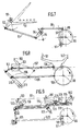
- La figure est une vue schématique en élévation d'une forme de réalisation de principe d'une machine d'encaissage selon l'invention, illustrant le moyen qu'elle constitue.
- La figure 2 est une vue schématique de dessus partielle de la machine d'encaissage représentée sur la figure 1.
- La figure 3 est une vue schématique à plus grande échelle en coupe transversale selon la ligne 3.3 de la figure 2.
- La figure 4 est une vue schematique en coupe selon la ligne 4.4 de la figure 3 illustrant deux variantes possibles et différents formats.
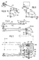
- les figures 5 et 6 sont deux vues de côté et de dessus respectivement d'une autre forme de réalisation de la machine concernant la partie mise en volume de la caisse.
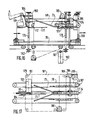
- Les figures 7, 8, 9, 10, 11, 12 sont six vues schématiques en élévation partielles illustrant la cinématique de fonctionnement de la machine.
- La figure 13 est une vue de dessus illustrant cette cinématique.
- les figures 14 et 15 sont deux vues schématiques, frontales des moyens de constitution du fond de la caisse.
- Les figures 16, 17, 18, 19 sont quatre vues respectivement de côté, de dessus, frontales illustrant la partie d'évacuation de la machine.
- The figure is a schematic elevational view of an embodiment in principle of a casing machine according to the invention, illustrating the means which it constitutes.
- FIG. 2 is a diagrammatic partial top view of the case packing machine shown in FIG. 1.
- FIG. 3 is a diagrammatic view on a larger scale in cross section along line 3.3 of FIG. 2.
- Figure 4 is a schematic sectional view along line 4.4 of Figure 3 illustrating two possible variants and different formats.
- Figures 5 and 6 are two side views and from above respectively of another embodiment of the machine relating to the volume portion of the box.
- Figures 7, 8, 9, 10, 11, 12 are six schematic views in partial elevation illustrating the kinematics of operation of the machine.
- Figure 13 is a top view illustrating this kinematics.
- Figures 14 and 15 are two schematic front views of the means of constitution of the bottom of the box.
- Figures 16, 17, 18, 19 are four respectively side, top, front views illustrating the discharge part of the machine.
L'invention concerne une machine d'encaissage 1 pour caisses américaines 2.The invention relates to a casing machine 1 for American boxes 2.
Une caisse américaine 2 est connue en soi et comporte quatre faces latérales 3, un fond 4 et un couvercle 5. Le fond 4 et le couvercle 5 sont constitués chacun de deux premiers rabats 6, 7 respectivement et de deux seconds rabats 8, 9 respectivement. Deux premiers rabats 6, 7 et deux seconds rabats 8, 9 sont attenants à deux faces latérales 3 opposées respectivement Au départ, la caisse 2 forme un flan aplati, les faces latérales 3 étant repliées l'une contre l'autre et les rabats 6, 7, 8, 9 libres et situés dans le même plan que les faces latérales 3.An American box 2 is known per se and has four lateral faces 3, a
La machine d'encaissage 1 est destinée également à un contenu 10 groupé en lots distincts de manière à pouvour être encaissé dans les différentes caisses successives américaines mises en volume et ouvertes.The casing machine 1 is also intended for
La machine d'encaissage 1 comporte, en premier lieu, des moyens d'amenée 11 de caisses vides sur lesquels sont placés d'amont en aval d'une part un magasin 12 de flans de caisses pliées à empilés et d'autre part, des moyens 13 d'ouverture, de mise en volume de la caisse 2 et de constitution de son fond 4 par pliage et solidarisation des rabats 6, 8.The casing machine 1 comprises, in the first place, means 11 for supplying empty boxes on which are placed from upstream to downstream on the one hand a
La machine d'encaissage 1 comporte, en deuxième lieu, des moyens d'amenée 14 du contenu 10 en lots aptes à être encaissés.The casing machine 1 comprises, secondly, means 14 for supplying the
La machine d'encaissage 1 comporte, en troisième lieu, des moyens 15 de transfert des lots de contenu 10 en vue de les placer dans les caisses 2 ouvertes et préparées à cet effet, interposés entre les parties extrêmes aval des moyens d'amenée 11 et des moyens d'amenée 14.The casing machine 1 comprises, thirdly, means 15 for transferring the batches of
La machine d'encaissage 1 comporte en quatrième lieu, des moyens d'évacuation 16 des caisses sur lesquels sont placés d'amont en aval les moyens de transfert 15 déjà mentionnés et des moyens 17 de constitution du couvercle 5 par pliage et solidarisation des rabats 7, 9 qui le constituent.The casing machine 1 comprises fourthly, means 16 for evacuating the boxes on which the transfer means 15 already mentioned are placed from upstream to downstream and means 17 for forming the
Les qualificatifs amont et aval s'entendent par rapport au sens de déplacement des moyens de transport (amenée ou évacuation) à savoir les caisses vides pour les moyens d'amenée 11, les lots de contenu 10 pour les moyens d'amenée 14 et les caisses 2 avec les lots de contenu 10 pour les moyens d'évacuation 16.The upstream and downstream qualifiers are understood in relation to the direction of movement of the means of transport (supply or evacuation), namely the empty boxes for the supply means 11, the
A l'entrée de la machine, on a, d'une part des flans empilés de caisses 2 et, d'autre part, des lots de contenu 10. En sortie, on a des caisses remplies des lots de contenus et fermées.At the entrance to the machine, there are, on the one hand blanks stacked with boxes 2 and, on the other hand, batches of
La machine 1 est portée par un bâti 18 reposant sur un plan d'appui 19 généralement horizontal (le sol), les moyens d'amenée 11, 14 et d'évacuation 16 s'étendant généralement horizontalement. En particulier, les moyens d'évacuation 16 sont placés substantiellement en prolongement des moyens d'amenée 11 de caisses vides et les moyens d'amenée 14 de contenu sont placés à côté des moyens d'évacuation 16, leur sens de fonctionnement étant opposé.The machine 1 is carried by a
Les moyens 13 d'ouverture, de mise en volume de la caisse 2 et de constitution de son fond 4 ainsi que les moyens 17 de constitution du couvercle 5 sont montés coulissants mais blocables sur des axes et déplacés le long de ces axes par des moyens d'entraînement associés à des moyens de commande numérique non représentés. Ces moyens de commande numérique commandent également les autres moyens constitutifs de la machine.The
Selon des caractéristiques importantes de l'invention, la machine 1 est généralement conçue, dans son ensemble, pour être réglable, les axes sur lesquels sont montés coulissants mais blocables les organes de la machine étant intégrés à la machine elle-même, plutôt qu'ajoutés à une structure de base connue. Ces axes sont agencés pour les déplacements et les réglages combinés et au moins partiellement simultanément des différents organes. Les moyens d'entraînement sont également intégrés à la machine 1, fixes dans leur ensemble et au moins partiellement communs aux différents axes ou organes. Les axes et/ou les moyens d'entraînement et/ou les organes de la machine sont accessibles ou non, l'accessibilité n'étant pas une condition déterminante pour le réglage.According to important features of the invention, the machine 1 is generally designed, as a whole, to be adjustable, the axes on which are slidably but lockable mounted the members of the machine being integrated into the machine itself, rather than added to a known basic structure. These axes are arranged for the movements and the combined and at least partially simultaneous adjustments of the various members. The drive means are also integrated into the machine 1, fixed as a whole and at least partially common to the different axes or members. The axes and / or the drive means and / or the components of the machine are accessible or not, accessibility being not a determining condition for the adjustment.
Les moyens d'entraînement sont préférentiellement constitués par des tiges filetées entraînées en rotation par un ou des moteurs. D'autres formes de réalisation équivalentes des moyens d'entraînement peuvent être envisagées (moteurs linéaires, vérins). Ainsi que cela est décrit ultérieurement, certaines au moins des tiges filetées s'étendent transversalement, de part en part de la machine 1, portées par le bâti 18, et comportent, au moins pour certaines d'entre elles, des filetages en sens opposés. Cette disposition constructive illustre l'intégration des moyens de réglage mentionnée ci-dessus et met en évidence la possibilité d'une plage de réglage particulièrement importante.The drive means are preferably constituted by threaded rods driven in rotation by one or more motors. Other equivalent embodiments of the drive means can be envisaged (linear motors, jacks). As described later, at least some of the threaded rods extend transversely, right through the machine 1, carried by the
Les moyens de commande comprennent dss moyens manuels d'affichage du format des caisses 2 à réaliser et à remplir et un automate programmable associé aux moyens manuels d'affichage et aux moyens d'entraînement de manière que, selon le réglage des moyens manuels d'affichage, l'automate programmable commande le déplacement des moyens d'entraînement jusqu'à amener les moyens 13, 17, dans les positions correspondants au format choisi. Les différents organes constitutifs sont ainsi réglés automatiquement, en combinaison et au moins partiellement simultanément.The control means comprise manual means for displaying the format of the boxes 2 to be produced and filled and a programmable automaton associated with the manual display means and the drive means so that, depending on the setting of the manual means of display, the programmable controller controls the movement of the drive means until the
Les moyens manuels d'affichage (non représentés) peuvent être constitués par un ou plusieurs boutons mobiles devant un ou des cadrans sur lequel les différents formats possibles sont mentionnés.The manual display means (not shown) may consist of one or more mobile buttons in front of one or more dials on which the different possible formats are mentioned.
Par exemple, les cadrans donnent la longueur, la largeur, et la hauteur des caisses pouvant varier notamment et respectivement entre 150 et 450 mm, 100 et 300 mm, 190 et 500 mm. Le réglage de la machine par les moyens d'affichage peut être continu ou discret.For example, the dials give the length, the width and the height of the boxes which can vary in particular and respectively between 150 and 450 mm, 100 and 300 mm, 190 and 500 mm. The adjustment of the machine by the display means can be continuous or discrete.
L'automate programmable peut comporter les éléments électroniques appropriés tels que mémoire, microprocesseur, etc...The programmable controller can include the appropriate electronic elements such as memory, microprocessor, etc ...
Selon une autre caractéristique préférée de l'invention, prise isolément et en combinaison avec les autres caractéristiques, les moyens de transfert 15 des lots de contenu 10 sont constitués par un robot à trois degrés de liberté (un axe vertical et deux axes horizontaux) de manière à permettre un remplissage des caisses 2 avec les lots de contenu 10 soit verticalement, soit latéralement. En conséquence, la machine d'encaissage 1, selon l'invention est polyvalente et selon la commande des moyens de transfert 15 peut être du type à encartonnage vertical ou à encartonnage latéral.According to another preferred characteristic of the invention, taken in isolation and in combination with the other characteristics, the
Les moyens de transfert 15 (non représentés sur la figure 1) comportent des moyens support 20 fixes associés au bâti 18 et une pluralité de bras 21 portés par les moyens support 20, déplacés grâce à des moyens d'entraînement tels que des vérins ou des moteurs, et terminés par des moyens de préhension 22 susceptibles de saisir un lot de contenu 10. Les moyens de préhension 22 peuvent être mécaniques ou pneumatiques notamment être constitués de ventouses de succion associées à un dispositif d'aspiration. Les moyens de préhension 22 sont constitués, par exemple, par une tête-matrice de succion amovible, comportant une ou plusieurs lignes et une ou plusieurs rangées de ventouses.The transfer means 15 (not shown in FIG. 1) comprise fixed support means 20 associated with the
Les moyens d'amenée 11 comportent des moyens de support et de guidage associés au bâti 18 destinés à des taquets mobiles d'entraînement des caisses 2 déplacées grâce à des moyens d'entraînement tels que des chaînes sans fin mobiles grâce à un ou plusieurs moteurs (non représentés).The supply means 11 comprise support and guiding means associated with the
Les moyens d'amenée 11, notamment les taquets mobiles d'entraînement des caisses 2, définissent, pour chaque caisse 2, un axe de référence, en l'occurrence l'arête horizontale inférieure amont de la caisse 2.The supply means 11, in particular the movable lugs for driving the boxes 2, define, for each box 2, a reference axis, in this case the lower horizontal edge upstream of the box 2.
De plus, cet axe de référence peut occuper plusieurs positions fixes de référence le long des moyens d'amenée 11, à savoir une première position initiale amont 23, une deuxième position intermédiaire d'ouverture 24, et une troisième position finale de constitution du fond 25. Ces positions 23, 24, 25 sont préférentiellement à égale distance l'une de l'autre.In addition, this reference axis can occupy several fixed reference positions along the supply means 11, namely a first initial
Le réglage des moyens 13 d'ouverture, de mise en volume et de constitution du fond 4 est réalisé par rapport aux positions fixes 23, 24, 25.The adjustment of the
Le magasin 12 est situé au droit de la première position 23. Il comporte plusieurs rails de guidage 26 propres à maintenir les flans de caisses pliés, superposés inclinés, par exemple à environ 45° par rapport aux moyens d'amenée 11. Le magasin 12 est, éventuellement, réglable pour être adapté aux différents formats de caisses ou encore il est amovible pour être remplacé par un autre magasin correspondant à un autre format ou encore il est prévu plusieurs magasins placés côte à côte, chacun adapté à un format, ces différents magasins étant montés sur des moyens d'entraînement (tels que tige filetée et moteur) associés aux moyens de commande numérique déjà mentionnés.The
Dans tous les cas, les moyens formant magasin 12 sont réglables préférentiellement automatiquement grâce à un ou plusieurs axes commandés numériquement.In all cases, the magazine means 12 are preferably adjustable automatically by means of one or more axes controlled digitally.
Des moyens (non représentés en détail) ont pour fonction de transférer les flans depuis le magasin 12 jusqu'aux moyens d'amenée 11. Ils peuvent être du type à bras mobile et ventouse de succion entraînés par un ou des moteurs, et par système bielle manivelle ou par came.Means (not shown in detail) have the function of transferring the blanks from the
A la deuxième position intermédiaire 24 se trouve un axe horizontal et transversal 27 sur lequel est monté pivotant un bras 28 terminé par une ou plusieurs ventouses 29 pouvant être appliquée sur la face latérale 3 de dessus attenante à l'axe de référence, de manière à permettre l'ouverture de la caisse 2. Eventuellement, en combinaison, une autre ventouse mobile, non représentée, est prévue pour être appliquée sur la face latérale de dessous attenante à l'axe de référence.At the second
Entre la deuxième position intermédiaire 24, environ, et l'extrémité aval des moyens d'amenée 11 se trouvent deux longerons 30, horizontaux, latéraux, situés de part et d'autre des moyens d'amenée légèrement au dessus de leur plan. Ces longerons 30 sont mobiles horizontalement et transversalement mais blocables en position de façon réglable grâce aux moyens de commande numérique. Ils s'étendent parallèlement et de part et d'autre des moyens d'amenée 11 et sont munis de paliers taraudés 31 horizontaux et tranversaux. La machine d'encaissage 1 comporte également au moins deux tiges filetées 32, horizontales et transversales, comportant à leurs deux parties extrêmes des filetages en sens opposés, coopérant avec les paliers taraudés 31 coaxiaux des deux longerons 30. Ces tiges filetées 32 sont placées en-dessous des moyens d'amenée 11 pour ne pas interférer avec les caisses 2. Des paliers de roulement horizontaux et transversaux 33 des tiges filetées 32 sont prévus dans le bâti 18. Au moins, un moteur d'entraînement non représenté permet l'entraînement en rotation et en synchronisme des tiges filetées 32 par l'intermédiaire de chaînes ou similaire 34 et donc le déplacement et le réglage de la position des longerons 30.Between the second
Les longerons 30 ont, par exemple, en section droite transversale, une forme d'équerre sur une branche verticale de laquelle se trouvent les paliers 31 et sur la branche horizontale de laquelle reposent les organes décrits ci-dessous.The
Le premier longeron (longeron de droite sur la figure 2 par rapport au sens d'avancement des caisses 2) supporte, d'amont en aval, en premier lieu, deux bras 35, 36 s'étendant dans un plan horizontal pivotant autour d'axes verticaux 37, 38, ayant pour fonction de plier les deux premiers rabats 6 du fond 4 par l'extérieur de la caisse 2. Le premier longeron 30 supporte, en deuxième lieu, des moyens d'encolage 39 placés horizontalement et dirigés vers le plan vertical médian de la machine 1. Ces moyens d'encolage 39 coopèrent avec les premiers rabats 6, pliés, grâce aux bras 35, 36. Enfin, le premier longeron 30 supporte, en troisième lieu, une plaque verticale et longitudinale 40 par l'intermédiaire d'un vérin 41, transversal. La plaque 40 coulisse en sens transversal et horizontal et a pour fonction de plier les seconds rabats 8 du fond 4, par l'extérieur de la caisse 2.The first spar (right spar in Figure 2 relative to the direction of advancement of the boxes 2) supports, from upstream to downstream, firstly, two
Le second longeron 30 (longeron de gauche sur la figure 2) supporte, en regard de la plaque 40, des moyens mobiles 42 formant contrepartie sur les premiers rabats 6 à l'intérieur de la caisse 2.The second spar 30 (left spar in FIG. 2) supports, opposite the
Les bras 35, 36 sont mobiles entre une position escamotée, (non représentée) dans laquelle ils sont dirigés vers l'extérieur de la machine et à l'écart des moyens d'amenée 11 et des caisses 2 et une position de travail où leurs plans d'appui respectif 43, 44 sont coplanaires dans le plan du fond 4 (figure 2). Ce plan est également celui dans lequel se trouve la buse des moyens d'encollage 35 et la plaque 40 dans une position externe antérieure.The
La plaque 40 est mobile entre deux positions extrêmes à savoir une position extrême antérieure de travail déjà mentionnée et une position extrême postérieure, escamotée, écartée du fond 4 et plus à l'écart des moyens d'amenée 11.The
En position de travail, la partie extrême amont du plan d'appui 43 du bras amont est située dans ou à proximité de la deuxième position de référence 24. Le bord extrême amont de la plaque 40 est situé, quant à lui, à l'endroit ou à proximité de la troisième position de référence 25. Les moyens d'encollage 39 sont situés légèrement à l'amont de la plaque 40, de manière à ne pas interférer avec elle.In the working position, the upstream end portion of the support plane 43 of the upstream arm is located in or near the
Les moyens formant contrepartie 42 sont constitués par une pluralité de vérins 45 juxtaposés agencés sous la forme d'une matrice comportant une ou généralement des lignes (figure 2) et une ou généralement des colonnes (figure 3), les vérins 45 étant portés par une plaque verticale et longitudinale 46 écartée des moyens d'amenée 11 et associée rigidement au second longeron 30. Chacun des vérins 45 comporte à l'extrémité de sa tige une plaquette élémentaire de contrepartie 47. Les vérins 45 sont commandés par les moyens de commande déjà mentionnés de manière qu'une partie seulement des vérins soit actifs à savoir ceux dont les plaquettes élémentaires de contrepartie 47 peuvent pénétrer dans la caisse 2 concernée.The counterpart means 42 are constituted by a plurality of juxtaposed
Par exemple les moyens 42 peuvent comporter trois lignes et quatre colonnes de vérins 45 (figure 4). Toutefois, le nombre de lignes et/ou de colonnes de vérins 45 peut être différent et adapté pour obtenir la précision souhaitée dans la réalisation des différentes dimensions de différentes contrepartie correspondant aux différents formats de caisses envisagés.For example, the
On se réfère maintenant aux figures 3 et 4 qui illustrent deux variantes possibles extrêmes de formats de caisse, le premier, le plus grand, représenté en traits plain et le second, le plus petit, représenté en trait interrompus. La totalité des verins 45 est mise en oeuvre pour le premier format tandis qu'un vérin seulement est mis en oeuvre pour le second format. Les deux longerons 30 sont respectivement à leur écartement maximum et à leur écartement minimum pour ces deux formats (le premier et le second). Le fonctionnement des vérins 45 et la course des vérins sont commandés depuis les moyens de commande de la machine 1.Reference is now made to FIGS. 3 and 4 which illustrate two possible extreme variants of box formats, the first, the largest, shown in plain lines and the second, the smallest, shown in broken lines. All of the
La réalisation d'une contrepartie 42 sous la forme d'une matrice commandée de façon sélective permet l'adaptation de la machine à tous les formats de caisses avec un maintien des rabats par l'intérieur particulièrement efficace ce qui assure une bonne solidarisation du premier et second rabats 4, 6 du fond 5. La matrice de vérin 45 est définie en dimensions par le plus grand format de caisse à traiter.The production of a
Les vérins 45 rendus actifs permettent le déplacement des plaquettes correspondantes 47 entre deux positions extrêmes à savoir une position escamotée (figure 2 et traits pleins figure 3) à l'écart des moyens d'amenée 11 de manière à ne pas interférer avec la caisse 2 et une position active de travail (traits mixtes figure 2 pour la première variante de caisses) ou les plaquettes 47 sont placées à l'intérieur de la caisse 2 en appui sur les premiers rabats 6 et donc pratiquemment dans le même plan que la plaque 40.The
Ainsi que cela résulte de la description qui précède, le déplacement simultané, sur une même distance, mais en sens opposé, des deux longerons 30 a pour effet que les caisses 2 en déplacement le long des moyens d'amenée 11 gardent un même plan de référence à savoir le plan vertical médian (de symétrie) de la machine. Cependant, d'autres formes de réalisation sont possibles ou le plan de référence serait, par exemple, le plan du fond 4.As follows from the above description, the simultaneous movement, over the same distance, but in the opposite direction, of the two
Les moyens d'amenée 11 à taquets mobiles comportent deux tronçons en prolongement à savoir un premier tronçon amont s'étendant entre la première et la deuxième positions de référence 23, 24 et un second tronçon aval s'étendant entre la deuxième et la troisième position de référence 24, 25 pour assurer le passage des caisses 2 à partir du magasin 12 successivement jusqu'à chacune de ces positions. De plus, le tronçon aval s'étend vers l'aval pour permettre la sortie des caisses se trouvant sur les moyens d'amenée 11.The feed means 11 with movable cleats comprise two sections in extension, namely a first upstream section extending between the first and second reference positions 23, 24 and a second downstream section extending between the second and
La machine comporte au moins deux portiques 50, fixes, verticaux et transversaux, enjambant les moyens d'amenée 11, placés par exemple respectivement entre les deuxième et troisième positions de référence 24, 25 et en aval de la troisième position 25 respectivement. Les traverses supérieures 51 horizontales et transversales des portiques 50 comportent des paliers 52 verticaux, médians, de guidage de tiges filetées 53. Des roulements d'entraînement 54 sont supportés par les traverses 51 de manière à pouvoir pivoter autour de leurs axes verticaux et comportent d'une part des taraudages internes coopérant avec les tiges filetées 53 pour assurer leur entraînement à coulissement et d'autre part des dents externes d'entraînement ou similaire. Une chaîne ou similaire 55 entraîne les roulements 54 en synchronisme par l'intermédiaire des dents. Un moteur (non représenté) permet d'entraîner les chaînes 55. Les tiges filetées 53 sont placées verticalement et de façon médiane. Aux extrémités inférieures des tiges filetées 53 est fixé au moins un longeron (et préférentiellement deux longerons légèrement écartés l'un de l'autre) 56, horizontal et supérieur, par exemple médian, mobile verticalement mais blocable en position de façon réglable grâce aux moyens de commande s'étendant au dessus des moyens d'amenée 11, notamment entre la deuxième position de référence 24 et l'extrémité aval des moyens d'amenées 11. Le longeron 56 peut être appliqué sur la face horizontale supérieure de la caisse 2 ouverte sans empêcher son coulissement. Des moyens d'équerrage 57 de la caisse 2 sont portés par le longeron 56 au droit de la plaque verticale de pliage 40 et des plaquettes 47 formant contrepartie 42. Cette structure est donc telle que le plan des moyens d'amenée 11 constitue également un plan de référence des caisses 2, les moyens d'équerrage 37 étant déplacés pour assurer leur réglage en fonction du format de la caisse 2 considérée.The machine comprises at least two
Les moyens d'équerrage 57 comportent, d'une part, un taquet cliquet amont 58 de blocage de la face transversale verticale amont de la caisse 2 par le haut, se trouvant dans le même plan que la troisième position de référence 25 et, d'autre part, un taquet mobile 59 de sollicitation de la face transversale verticale aval de la caisse 2 par le haut et, vers l'amont, porté par une chaîne 60 entraînée par un vérin ou similaire 61 jusqu'à une position de blocage réglables grâce à des moyens de commande mécanique automatique -tel qu'un pignon à friction- dans laquelle la caisse est maintenue parfaitement à l'équerre entre les taquet amont inférieur des moyens d'amenée 11 et les deux taquets supérieurs 58, 59. L'emploi d'un pignon à friction à l'avantage d'un réglage automatique de la position du taquet 59. La chaîne 60 et le vérin 61 sont placés au-dessus du longeron 56 pour ne pas interférer avec la caisse 2 ouverte. Le taquet 58 forme cliquet pour permettre le passage des caisses 2 de l'amont vers l'aval. Le taquet 59 peut se trouver dans une position de repos escamotée au dessus du longeron 56.The squaring means 57 comprise, on the one hand, an
La machine d'encaissage 1 selon l'invention peut comporter, en aval des moyens d'amenée 11, des moyens 48 de coulissement et/ou de pivotement de la caisse préalablement mise en volume et ouverte par les moyens 13 afin de la transférer sur les moyens d'évacuation 16 de manière que l'ouverture de la caisse soit placée soit latéralement, soit sur le dessus, selon que la machine d'encaissage est du type à encaissage latéral ou à encaissage vertical.The casing machine 1 according to the invention may comprise, downstream of the supply means 11, means 48 for sliding and / or pivoting the box previously volume-set and opened by the
Les moyens d'amenée 14 du contenu 10 peuvent se présenter sous la forme d'un tapis roulant comportant des barrettes transversales de blocage 49 permettant d'entraîner et de grouper les contenus 10 en lots successifs organisés.The supply means 14 for the
Les moyens 16 d'évacuation comportent également un ou plusieurs convoyeurs à bande pour l'entraînement des caisses 2, notamment remplies, vers l'aval.The discharge means 16 also include one or more conveyor belts for driving the boxes 2, in particular filled, downstream.
La machine 1 comporte au moins deux portiques 62, fixes, verticaux et transversaux, enjambant les moyens d'évacuation 16 et dont les traverses supérieures 63 horizontales et transversales comportent des paliers de guidage 64 pour des tiges filetées 65 verticales. Des roulements d'entraînement 66 sont portés de manière à pouvoir pivoter autour de leurs axes verticaux par les paliers 64 et comportent, d'une part, des taraudages coopérant avec les tiges filetées 65 pour assurer leur entraînement et, d'autre part, des dents externes d'entraînement ou similaires. Une chaîne ou similaires 67 entraînée par un moteur (non représenté) entraîne les roulements de manière que les tiges filetées 65 soient entraînées à coulissement en synchronisme. Aux extrémités inférieures des tiges filetées 65 est fixé un longeron 68, supérieur, médian, mobile verticalement mais blocable en position de façon réglable grâce aux moyens de commande numérique, s'étendant au dessus des moyens d'évacuation 16. Ce longeron 68 supporte d'amont en aval, en premier lieu, un bras 69 pivotant autour d'un axe horizontal et transversal 70 et entraîné par un vérin 71 ayant pour fonction de plier deux premiers rabats 7 du couvercle 5; en deuxième lieu, des moyens d'encollage 72 des premiers rabats 7 préalablement pliés; en troisième lieu et de façon fixe, deux rampes 73, inclinées de haut en bas, et de l'amont vers l'aval et de l'extérieur vers l'intérieur c'est-à-dire se rapprochant l'une de l'autre tout en se rapprochant des moyens d'évacuation 16 dans le sens d'advancement des caisses 2 et ayant pour fonction de plier les deux seconds rabats 8 du couvercle 5 lors de l'avancement de la caisse 2 sur les moyens d'évacuation 16; et, enfin, en quatrième lieu, une bande sans fin 74 placée horizontalement et longitudinalement, appliquée sur les seconds rabats 8 ainsi pliés, c'est-à-dire sur le couvercle 5, entraînée en défilement par un moteur 75 lui-même porté par le longeron 68. La bande sans fin 74 a pour fonction de maintenir les seconds rabats 8 appliqués sur les premiers rabats 7 le temps nécessaire à la prise de la colle distribuée par les moyens d'encollage 72.The machine 1 comprises at least two
Le bras 69 est mobile entre deux positions extrêmes, à savoir, une position escamotée inactive où il est placé horizontalement en partie supérieure et à l'écart de la caisse 2 placée en dessous et une position de travail où il est placé dans le sens général vertical descendant avec son plan d'appui 76 horizontal. Dans ce même plan horizontal sont situées l'extrémité des moyens d'encollage 72 et la bande sans fin 74. Les moyens d'encollage 72 sont placés de façon générale verticalement et vers le bas. Entre le bras 69 et les moyens d'encollage 72 est prévue une plaque d'appui 77 inclinée à l'amont et horizontale à l'aval sous laquelle peuvent glisser les premiers rabats 7 et dont la fonction est d'éviter que ces rabats 7 ne se déplient après avoir échappé au bras 69. Cette plaque 77 est située immédiatement entre le bras 69 et les moyens d'encollage 72. Les extrémités inférieures aval des rampes 73 sont également situées dans le plan mentionné précédemment. Pour que la solidarisation effective du couvercle 5 soit assurée la bande sans fin 74 s'étend sur une certaine longueur appropriée, en fonction de la vitesse de la bande et de la durée nécessiare au collage.The
La machine 1 comporte également deux bandes sans fin 78 latérales placées de part et d'autre des moyens d'évacuation 16, appliquées sur les faces latérales longitudinales 3 des caisses 2 et portées par des longerons longitudinaux 79 mobiles et réglables et des tiges filetées 80 horizontales transversales et placées en dessous des moyens d'évacuation 16, ces tiges filetées 80 étant entraînées en rotation par un moteur et des chaînes, de manière à permettre le rapproache- ment ou l'éloignement des bandes sans fin 78 en fonction de la caisse 2 considérée.The machine 1 also comprises two endless
Les différents moteurs décrits à propos des moyens 13 et des moyens 17 ainsi que les moteurs des moyens de transfert 15 ou encore celui associé aux bandes sans fin 78 sont commandés par les moyens de commande numérique mentionnés précédemment.The various motors described with regard to the
Naturellement, la description qui vient d'être faîte ne concerne qu'un mode de réalisation possible de l'invention, d'autres formes de réalisation étant néanmoins possible.Naturally, the description which has just been given relates only to one possible embodiment of the invention, other embodiments being nevertheless possible.
On décrit maintenant, en référence aux figures 5 à 19 une forme de réalisation effective de la machine 1 conforme en général à la forme de réalisation de principe décrite précédemment.A description will now be given, with reference to FIGS. 5 to 19, of an effective embodiment of the machine 1 generally conforming to the embodiment of principle described above.
Les moyens d'alimentation 12 sont réglables. A cet effet, les rails 26 sont portés perpendiculairement par deux bras 81 inclinés à environ 45° sur l'horizontale, d'amont vers l'aval et de bas en haut, eux-mêmes portés par deux pièces support 82 s'étendant longitudinalement et latéralement, à écartement réglable, ayant, en élévation verticale une forme générale angulaire comportant un tronçon horizontal et un tronçon vertical, portées par deux tiges filetées horizontales et transversales respectivement amont et aval 83 et 84 chacune avec deux pas de vis opposés, coopérant respectivement avec des paliers taraudés des pièces support 82, respectivement à l'extrémité amont des tronçons horizontaux proches de la zone d'association avec les bras 81 et à l'extrémité inférieure des tronçons verticaux. Des poulies dentées 85 et 86 calées sur les tiges filetées 83 et 84 engrennent une chaîne sans fin 87 elle-même entraînée par un moteur 88 fixe dans son ensemble. Des paliers 89 du bâti 18 assurent le maintien de tiges filetées 83 et 84.The supply means 12 are adjustable. To this end, the
Ainsi que cela résulte de cette structure, les rails 26 du magasin 12 sont d'écartement réglable de façon égale et concomittante à l'écartement de deux glissières 90 longitudinales, latérales et horizontales s'étendant le long de la partie de la machine 1 sur laquelle la caisse 2 est mise en volume avec son fond 4 constitué rigidement (avant les moyens 48). Ces glissières 90 ont, en section droite transversale, une forme d'équerre et elles ont pour double fonction de constituer un plan d'appui et un guidage latéral des caisses 2 ou de flans qui les constituent.As this results from this structure, the
Les moyens pour transférer les flans successivement et à l'unité du magasin 12 jusqu'aux moyens d'amenée 11 (taquet mobile) sont constitués, dans cette forme de réalisation, par un bras 91, longitudinal, médian placé entre les glissières 90 (ou en variante plusieurs bras côte à côte), calé axialement et à rotation libre sur la tige filetée amont 83 formant axe de pivotement. Le bras 91 comporte, solidaire, une biellette 92 à environ 120° dirigée vers l'arrière et l'amont lorsque le bras 91 est au repos horizontalement. A la biellette 92 est articulée l'extrémité d'une tige 93 elle-même articulée, à son autre extrémité à l'extrémité d'un levier 94 monté articulé dans sa partie centrale, librement autour de la tige filetée aval 84 et à l'autre extrémité duquel est articulée l'extrémité d'un levier 96 monté pivotant à son autre extrémité autour d'un axe 97 horizontal, transversal, fixe, placé à la partie inférieure de la machine 1 sensiblement entre les moyens d'ouverture de la caisse 2 et les moyens de réalisation finale du fond 4, c'est-à-dire entre les positions 24, 25. En partie médiane, le levier 96 comporte un ergot ou similaire coopérant avec une came 98 montée sur un axe 99, horizontal transversal et fixe, également placé à la partie inférieure de la machine 1, notamment à l'aval de l'axe 97. Le bras 91 comporte une pluralité de ventouses d'aspiration. Le cas échéant, il est prévu des moyens pour sélectivement actionner les ventouses proches de la tige filetée 83 et au contraire, ne pas actionner celles éloignées cela en fonction du format du flan à transférer. Le bras 91 est mobile entre deux positions: une position horizontale dirigée vers l'aval et une position d'extraction inclinée en correspondance avec le magasin 12 notamment de l'amont vers l'aval et de bas en haut à environ 60°.The means for transferring the blanks successively and to the unit of the
Les moyens d'amenée sont, comme indiqué précédemment, préférentiellement du type taquet mobile d'entraînement. Plus précisément, il est prévu trois ou trois séries de taquets à savoir un premier taquet 100 entre la position amont 23 et la position intermédiaire 24, un deuxième taquet 101 entre la position intermédiaire 24 et la position finale 25 et un troisième taquet 102 entre la position finale 25 et la zone des moyens 48 c'est-à-dire lorsque la caisse 2 est constituée. Préférentiellement, il est prévu des paires de taquets 100, 101, 102 proches des glissières 90. Le taquet 100 est porté par un premier chariot 103 et les taquets 101 et 102 par un second chariot 104. Les chariots 103 et 104 sont montés à coulissement horizontal longitudinal au moyen d'une ou plus généralement de deux rails de roulement 105, horizontaux et longitudinaux sur lesquels roulent et sont guides des galets 106 des chariots.The supply means are, as indicated above, preferably of the movable cleat drive type. More specifically, three or three series of tabs are provided, namely a
Une biellette 107 relie les deux chariots 103,104 écartés l'un de l'autre d'une distance fixe pour assurer leur déplacement en synchronisme. Le mouvement de coulissement alternatif des chariots 103,104 vers l'amont et vers l'aval est assuré notamment grâce à la biellette 107 et à partir d'une came 108 montée sur l'axe 99 entraînant une bielle 109 articulée, à son autre extrémité à la partie médiane d'un levier 110 articulé, à sa première extrémité inférieure à un axe 111 horizontal, transversal, inférieur fixe de la machine 1, situé approximativement à l'aplomb du magasin 12 et articulé, à sa seconde extrémité supérieure à une biellette de renvoi 112 elle-même articulée au chariot 103. Le levier 110 est déplacé entre deux positions extrêmes chacune à environ 45° sur l'horizontale, vers l'amont et vers l'aval respectivement.A
Par ailleurs, les taquets 100, 101, 102 sont eux-mêmes portés par des corps montés articulés sur les chariots respectifs 103 et 104 autour d'axes 113, 114 et 115 respectivement. En dessous des axes 113, 114, 115 se trouve un rail 116 horizontal et longitudinal. Préférentiellement, il est prévu deux rails latéraux. Le rail 116 est agencé coulissant verticalement au moyen d'un dispositif approprié tel qu'un parallélogramme déformable à biellettes 117 entraîné par des moyens d'entraînement tel qu'une came 118 calée sur l'axe 99 entraînant, via un maneton 119 articulé sur l'axe 97, une biellette 120 généralement horizontale et longitudinale, articulée à son extrémité opposée à plusieurs biellettes désignées dans leur ensemble par 121 articulées entre elles et finalement au parallélogramme déformable à biellette 117. Dans le rail 116 formant glissière sont montés des galets 122 et 123 portes par des biellettes 124 et 125 respectivement, articulées sur les axes 113 et 114 respectivement et associées rigidement aux corps des taquets 100 et 101 respectivement. De plus, une biellette de renvoi 126 articulée aux deux corps des taquets 101 et 102 de manière à assurer leur rotation synchrone et en sens opposé, les taquets 100 et 101 pivotant de façon synchrone et dans le même sens. Le rail 116 est mobile entre deux positions extrêmes supérieure et inférieure dans lesquelles, respectivement, les taquets 100, 101 et 102 sont en position active saillante et en position inactive escamontée, ceci par rapport au plan de référence constitué par les glissières 90. Cet agencement permet le mouvement d'avance des taquets 100, 101 et 102 vers l'aval en position active en leur retour vers l'amont en position inactive.Furthermore, the
Comme indiqué précédemment, les taquets 100,101,102 sont préférentiellement par paire et situés latéralement afin de mieux prendre la caisse 2 et sont réglables en écartement transversal de manière à prendre la caisse plutôt vers ses bords latéraux, ce qui améliore le guidage. A cet effet, les taquets sont montés coulissant axialement le long d'arbres cannelés tels que 195, au moyen de manchons cannelés complémentaires 196 coopérant avec les arbres 195. Au manchon 196 est associé rigidement un galet à gorge 197 également monté sur et autour de l'arbre cannelé 195. Une saillie longitudinale 198 formant rail coopére avec la gorge du galet 197. Cette saillie longitudinale 198 formant rail est attenante solidairement et cinématiquement au longeron de l'un des longerons 30. Les arbres cannelés 195 sont portés de manière à être pivotants. Ils sont mobiles à coulissement transversal (par rapport à leur axe) et longitudinal (par rapport à la machine). Les saillies formant rails provoquent le coulissement axial des manchons 196 et donc le réglage transversal des taquets.As indicated above, the
Le bras 28 portant la ventouse 29 d'ouverture de la caisse 2 est entraîné par une biellette 127 qui lui est articulée et qui est commandée par une came 128 calée sur l'axe 99. Par example, la came 128 entraîne via un ergot ou similaire un maneton 129 articulé sur l'axe 97 à son extrémité inférieure et auquel est articulé, à son extrémité supérieure une biellette 130 généralement horizontale et longitudinale autour d'un axe 132 et auquel est articulé la biellette 127. Cet agencement est tel que le bras 28 peut pivoter de 90° entre deux positions extrêmes respectivement horizontal dirigé vers l'aval et vertical ascendant.The
Préférentiellement, il est également prévu une ou plusieurs ventouses 133 destinée à être appliquée sur et maintenir la face latérale horizontale inférieure de la caisse 2 lors de son ouverture pour la mise en volume. Cette ou ces ventouses 133 sont à axe vertical et portées, directement ou non, par un bras 134 généralement vertical et guidé par des moyens de guidage tels qu'un fourreau 135, commandé à coulissement vertical par une biellette 136 elle-même commandée par une came 137 calée sur l'axe 99, la biellette 136 étant par ailleurs articulée autour d'un axe horizontal transversal, inférieur, fixe 138 situé approximativement en dessous et à l'aplomb de la troisième position finale 25. Cette structure permet que la ou les ventouses 133 soient mobiles entre une position supérieure active de travail et une position inférieure inactive escamotée.Preferably, there is also provided one or
Les bras 35,36 sont également entraînés autour de leurs axes 37, 38 à partir de deux cames 139, 140 respectivement calées sur l'axe 99, au moyen d'une tringlerie appropriée, étant souligné que les axes 37 et 38 sont verticaux et l'axe 99 horizontal transversal. Par exemple, la came 139 commande un maneton 141 monté articulé sur l'axe 97, sur lequel est montée articulée une bielle 142, à une extrémité, laquelle bielle 142 généralement horizontale est articulée, à son autre extrémité à l'extrémité d'un levier 143 articulé dans sa partie médiane autour d'un axe 144 horizontal et transversal situé au moins sensiblement à l'aplomb du magasin 12, le levier 143 est articulé à son autre extrémité à une bielle 145 articulée à une biellette 146 d'une seule pièce avec le bras 35 et donc montée pivotante autour de l'axe 37. La bielle 145 est articulée au levier 143 autour d'un axe horizontal et à la biellette 146 autour d'un axe vertical. Une structure similaire est prévue en ce qui concerne la came 140 et le bras 36 à savoir maneton 147, bielle 148, levier 149, bielle 150, et biellette 151. Le levier 149 est articulé autour de l'axe 144. Entre la bielle 150 et la biellette 151 est interposé un dispositif de renvoi 152, à biellette et levier.The
Un moteur unique 153 avec moto-réducteur et renvoi d'angle, placé en parie inférieure de la mâchine, porté par le bâti 18, notamment sensiblement à l'aplomb de la position finale 25 entraîne l'axe 99 et donc les cames 98, 108, 118, 128, 137, 139 et 140, l'axe 99 est porté par des paliers 154.A
Dans la partie aval de constitution et de solidarisation du fond 4, la machine 1 comporte, au lieu et place de la plaque 40 deux barres 155 s'étendant horizontalement et longitudinalement portées par deux bras 156 (ou paires de bras) articulés autour d'axes horizontaux et longitudinaux 157 dans un même plan vertical et à proximité l'un de l'autre, l'ensemble 155, 156, 157 formant une sorte de pince étendue axialement s'ouvrant et se fermant. Les axes 157 sont portés par un chariot 158 porté et monté coulissant verticalement grâce à deux colonnes filetées 159 verticales coopérant avec des taraudages du chariot 158, placées dans un même plan vertical longitudinal. Ces deux colonnes filetées 159 sont elles-mêmes portées, à leurs parties inférieures par le longeron 30 correspondant et, à leurs parties supérieures par une entretoise 160 horizontale longitudinale et supérieure maintenue à écartement fixe par l'intermédiaire de tiges ou équivalents 161, horizontales et transversales d'une autre entretoise 162 horizontale, longitudinale, supérieure, coplanaire à l'entretoise 162 mais du côté latéral opposé de la machine, laquelle entretoise 162 supporte deux colonnes verticales 163 placées en regard des colonnes filetées 159 mais de l'autre côté latéral de la machine. Les colonnes 163 sont, a leur tour, portées par un ou des chariots 164, menés, roulant dans le sens transversal horizontal, à coulissement et par l'intermédiaire de galets 165 sur des glissiéres horizontales et transversales 166 portées fixement par le bâti 18. Deux autres colonnes filetées 167 à proximité des colonnes 163 s'étendent verticalement portées entre et par le ou les chariots 164 et l'entretoise 162. Des pignons dentés 168 calés aux extrémités supérieures saillantes des colonnes filetées 159 et 167, reliées par une chaîne sans fin 169 ou tout moyen équivalent associé à un moteur 170, sur lequel on reviendra ultérieurement, permet l'entraînement synchrone et dans le même sens des colonnes filetées 159 et 167. Sur les colonnes filetées 167 est monté un chariot 171 par des taraudages appropriés, ce chariot 171 étant placé horizontalement dans le même plan mais en regard du chariot 158. Le chariot 171 supporte les moyens formant contrepartie 42. Les deux chariots 158, 171 sont donc déplacés en synchronisme et sont horizontalement et transversalement à une distance constante l'un de l'autre. Outre les tiges 161, il est prévu pour maintenir cette distance une ou plusieurs tiges horizontales transversales inférieures 172.In the downstream part for forming and securing the
Des moyens tels que des vérins ont pour fonction l'ouverture et la fermeture de la pince 155, 156, 157.Means such as jacks have the function of opening and closing the
Les moyens formant contrepartie 42, sont, dans cette forme de réalisation constitués par une ligne unique de vérins 45 disposés dans un plan horizontal destinées à venir s'appliquer sur le fond de la caisse 2, par l'intérieur, dans sa zone médiane, en regard et contre les deux bras 156 rapprochés l'un de l'autre, la pince correspondante étant fermée. Le changement de formant de la caisse 2 est pris en compte pour les vérins 45, seulement en cas de changement de longueur horizontale, le nombre de vérins actifs étant adaptés en conséquence. La structure décrite précédemment avec les tiges 161 et 172 à pour conséquence que la course des vérins 45 est constante quel que soit le format de caisse 2 (en sens transversal).The counterpart means 42 are, in this embodiment constituted by a single line of
Le longeron 56 de la machine est, dans cette forme de réalisation, porté par un cadre horizontal supérieur 173 monté à coulissement vertical grâce à quatre colonnes filetées verticales 174 d'axes fixes portés par le bâti 18 de la machine. Ces colonnes filetées 174 sont agencées, notamment reliées par des pignons, des chaînes ou équivalent pour tourner en synchronisme dans le même sens. Selon l'invention les colonnes filetées 174 sont entraînées par le même moteur 170 que les colonnes filetées 159 et 167, avec, toutefois, un réducteur de manière que la course de coulissement du cadre 173 soit le double de celui des chariots 158 et 171 ou que la course des chariots 158 et 171 soit la moitié de celle du cadre 173. A cet effet, le moteur 170 peut être d'axe vertical et logé à la partie inférieure de la machine, fixe dans son ensemble sur son bord latéral et entraîner les colonnes filetées 159 et 167 via une roue dentée 175 double de celle 176 entraînant les colonnes filetées 174, la roue dentée 175 est d'axe fixe vertical porté par le bâti 18. Compte tenu du déplacement des colonnes filetées 159, il est prévu entre celles-ci et l'arbre de la roue dentée 175 une articulation à la cardan 177. Ainsi que cela résulte de la description qui précède, concernant la forme de réalisation de principe les longerons 30 sont montés coulissants horizontalement et transversalement, en sens opposé et en synchronisme grâce à des tiges filetées 32 et un moteur 178 et supportent les glissières 90.The
Ainsi que cela résulte de ce qui précéde, les déplacements des longerons 30, donc des taquets 100,101,102, en sens transversal est indépendant mais combiné au déplacement relatif des vérins 45, d'où l'existence du chariot 171. Les colonnes filetées 159 et 167 non seulement tournent deux fois moins vite que les colonnes filetées 174 mais encore les axes verticaux des colonnes filetées 159 et 167, sont déplaçables horizontalement et transversalement alors que les axes des colonnes filetées 174 sont fixes, d'où la structure de cadre 173 d'encombrement plus large que celui des colonnes filetées 159 et 167 dans leurs différentes positions. La pince 155, 156, 157 occupe, quant à elle, une position relative transversale fixe par rapport au longeron 30 correspondant de manière à se trouver en permanence dans la même position relative par rapport au fond 4 de la caisse 2 quel que soit son format.As this results from the above, the displacements of the
On considère maintenant la partie évacuation de la machine 1. Le longeron 68 est porté directement par quatre colonnes filetées 179 d'axes verticaux portées en partie basse par le bâti 18. les colonnes filetées 179 sont entraînées à partir d'un moto-réducteur 180 par une chaîne 181 et des pigons dentés 182. Le bras 69 est entraîné par un moto-réducteur 183 et une bielle manivelle 184, au lieu et place d'un vérin. La plaque d'appui 77 se prolonge vers l'aval au délà des moyens d'encollage 72, jusque sous la partie médiane des rampes 73. Un moto-réducteur unique 185 porté par le bâti de la machine, en position fixe entraîne d'une part, la bande sans fin 74 par l'intermédiaire d'un tambour 186 d'axe horizontal et, d'autre part par des tambours identiques 187 d'axes verticaux les bandes sans fin latérales 78. A cet effet, le moto-réducteur 185 est associé au tambour 186 par une boîte d'angle coulissante 188 sur un arbre claveté 189 et aux tambours 187 par des transmissions coulissantes à cardans 190. Enfin, il est prévu des galets 191 de maintien latéral de la caisse à sa partie supériure, d'axes verticaux portés par deux supports longitudinaux et horizontaux eux-mêmes portés par des tiges filetées transversales 192 par des paliers 193 portés par le longeron 68. Un moto-réducteur 194 également porté par le longeron 68 permet l'entraînement des tiges filetées donc le réglage des galets 191.We now consider the discharge part of the machine 1. The
Claims (28)
Priority Applications (1)
| Application Number | Priority Date | Filing Date | Title |
|---|---|---|---|
| AT87401109T ATE60295T1 (en) | 1986-05-16 | 1987-05-15 | PACKING MACHINE FOR ''AMERICAN'' BOXES. |
Applications Claiming Priority (2)
| Application Number | Priority Date | Filing Date | Title |
|---|---|---|---|
| FR8607096A FR2598680B1 (en) | 1986-05-16 | 1986-05-16 | CASING MACHINE FOR AMERICAN BOXES |
| FR8607096 | 1986-05-16 |
Publications (2)
| Publication Number | Publication Date |
|---|---|
| EP0248700A1 EP0248700A1 (en) | 1987-12-09 |
| EP0248700B1 true EP0248700B1 (en) | 1991-01-23 |
Family
ID=9335340
Family Applications (1)
| Application Number | Title | Priority Date | Filing Date |
|---|---|---|---|
| EP87401109A Expired - Lifetime EP0248700B1 (en) | 1986-05-16 | 1987-05-15 | Packaging machine for "american" boxes |
Country Status (6)
| Country | Link |
|---|---|
| US (1) | US4807428A (en) |
| EP (1) | EP0248700B1 (en) |
| AT (1) | ATE60295T1 (en) |
| CA (1) | CA1288678C (en) |
| DE (1) | DE3767569D1 (en) |
| FR (1) | FR2598680B1 (en) |
Families Citing this family (21)
| Publication number | Priority date | Publication date | Assignee | Title |
|---|---|---|---|---|
| IT1228719B (en) * | 1989-03-15 | 1991-07-03 | Augusto Marchetti | TAPING MACHINE FOR PARALLELEPIPED CARDBOARD BOXES WITH CLOSURE ON THE SIDES. |
| FR2652561B1 (en) * | 1989-10-02 | 1992-04-10 | Vega Automation | PROCESS AND DEVICE FOR CONSTITUTING, CLOSING AND SOLIDARIZING RECIPROCALLY THE FLAPS OF A CASE SUCH AS AN AMERICAN CARDBOARD CASE. |
| US5704196A (en) * | 1995-09-21 | 1998-01-06 | Douglas Machine Limited Liability Company | High speed blank set-up apparatus and methods |
| US5700998A (en) * | 1995-10-31 | 1997-12-23 | Palti; Yoram | Drug coding and delivery system |
| IT1292804B1 (en) | 1997-03-18 | 1999-02-11 | Ima Spa | EQUIPMENT FOR STAMPING, ENGRAVING, UNDRAWING OF BLISTER PACKS OBTAINED FROM A HONEYCOMB TAPE. |
| US7146784B1 (en) | 1998-01-16 | 2006-12-12 | Meadwestvaco Packaging Systems, Llc | Machine for packaging a plurality of articles in a carton, and method of forming a carton |
| US6080095A (en) * | 1999-03-31 | 2000-06-27 | Tien Heng Machinery Co., Ltd. | Carton-shaping machine |
| US6309335B1 (en) * | 1999-11-10 | 2001-10-30 | Delaware Capital Formation | Vertically displaced hopper for bliss machines |
| ITBO20050584A1 (en) * | 2005-09-28 | 2007-03-29 | Marchesini Group Spa | METHOD FOR PACKAGING ITEMS IN BOXED CONTAINERS AND MACHINE THAT ACTIVATE THIS METHOD |
| US20070204567A1 (en) * | 2006-03-03 | 2007-09-06 | R.A. Jones & Co. Inc. | Top load cartoner |
| FR2907101B1 (en) * | 2006-10-11 | 2009-01-16 | Sidel Participations | DEVICE FOR TRANSFERRING CARBON BOXES. |
| EP1980494A1 (en) * | 2007-04-13 | 2008-10-15 | Diseños Integrales del Embalaje, s.a. | Device for adjusting the height of folding boxes and the boxes to be used with such a device |
| US8323165B2 (en) * | 2009-09-14 | 2012-12-04 | Thiele Technologies, Inc. | Method for forming a container |
| RU2573373C2 (en) * | 2010-06-29 | 2016-01-20 | ПЭКСАЙЗ ЭлЭлСи | Optimisation of production of packaging products |
| JP5351946B2 (en) * | 2011-08-10 | 2013-11-27 | 株式会社安川電機 | Packing equipment |
| AU343832S (en) * | 2012-06-26 | 2012-08-10 | Adelaide Control Eng Pty Ltd | A containerised automated drum packing module |
| CN103144788B (en) * | 2013-03-19 | 2015-08-26 | 苏州雪诺机械制造有限公司 | There is the cartoning sealing machine of pressure draw box mechanism |
| US20170190449A1 (en) * | 2014-07-03 | 2017-07-06 | Gea Food Solutions Germany Gmbh | Packaging machine for packages with an l-board |
| US11505341B1 (en) * | 2018-10-05 | 2022-11-22 | Douglas Machine Inc. | Robotic case packer platform and packing method |
| WO2020169098A1 (en) * | 2019-02-22 | 2020-08-27 | 青岛萨沃特机器人有限公司 | Box sealing apparatus and packaging machine |
| CN118418517B (en) * | 2024-07-01 | 2024-10-18 | 厦门安妮企业有限公司 | Box folding equipment |
Family Cites Families (18)
| Publication number | Priority date | Publication date | Assignee | Title |
|---|---|---|---|---|
| BE505317A (en) * | ||||
| GB535347A (en) * | 1939-11-29 | 1941-04-07 | Alfred German Rose | Improvements in packaging apparatus |
| US2280773A (en) * | 1940-08-03 | 1942-04-28 | Jl Ferguson Co | Carton opening, folding, and positioning machine |
| DE871420C (en) * | 1941-06-22 | 1953-03-23 | Jagenberg Werke Ag | Method and machine for manufacturing, filling and closing containers |
| US3164938A (en) * | 1962-03-16 | 1965-01-12 | American Mach & Foundry | Wrapping machine |
| CH418956A (en) * | 1962-11-23 | 1966-08-15 | Kirsten Rolf | Machine for cartoning all kinds of filling goods |
| FR2029300A5 (en) * | 1969-01-24 | 1970-10-16 | Savoye | |
| US3611884A (en) * | 1970-01-26 | 1971-10-12 | William J Hottendorf | Box making machine |
| US3885372A (en) * | 1974-06-07 | 1975-05-27 | Peres Electronic Machines Inc | Automatic random case sealer |
| DE2702481A1 (en) * | 1977-01-21 | 1978-07-27 | Ferrero Ohg | Automatic chocolates packing mechanism - has individual reciprocating suction heads moving chocolates from conveyor to recessed tray to that chocolate shapes are not distorted |
| DD129767B1 (en) * | 1977-02-07 | 1982-03-31 | Erhard Blechschmidt | DEVICE FOR STACKING PRISMATIC PACKAGES |
| US4163414A (en) * | 1977-02-23 | 1979-08-07 | Wayne Automation Corp. | Method of erecting flat folded cases |
| US4150523A (en) * | 1977-11-15 | 1979-04-24 | Wrapmatic S.P.A. | Automatic machine for packing products of parallelepiped shape, particularly reams of paper |
| US4233798A (en) * | 1979-07-30 | 1980-11-18 | Helding James R | Box closing machine |
| SE433590B (en) * | 1980-06-25 | 1984-06-04 | Sundpacma Ab | METHOD AND DEVICE FOR HANDLING AND REPRESENTING SIZE WINDOWS |
| CH650722A5 (en) * | 1983-02-21 | 1985-08-15 | Bobst Sa | MACHINE FOR MAKING FOLDING BOXES. |
| DE3339924A1 (en) * | 1983-11-04 | 1985-05-15 | Robert Bosch Gmbh, 7000 Stuttgart | PACKING MACHINE |
| DE3417508A1 (en) * | 1984-05-11 | 1985-11-14 | Uwe 7024 Filderstadt Knuth | Cartoning apparatus |
-
1986
- 1986-05-16 FR FR8607096A patent/FR2598680B1/en not_active Expired
-
1987
- 1987-05-14 US US07/049,472 patent/US4807428A/en not_active Expired - Fee Related
- 1987-05-15 DE DE8787401109T patent/DE3767569D1/en not_active Expired - Lifetime
- 1987-05-15 AT AT87401109T patent/ATE60295T1/en not_active IP Right Cessation
- 1987-05-15 CA CA000537280A patent/CA1288678C/en not_active Expired - Lifetime
- 1987-05-15 EP EP87401109A patent/EP0248700B1/en not_active Expired - Lifetime
Also Published As
| Publication number | Publication date |
|---|---|
| CA1288678C (en) | 1991-09-10 |
| FR2598680B1 (en) | 1989-04-21 |
| EP0248700A1 (en) | 1987-12-09 |
| DE3767569D1 (en) | 1991-02-28 |
| ATE60295T1 (en) | 1991-02-15 |
| FR2598680A1 (en) | 1987-11-20 |
| US4807428A (en) | 1989-02-28 |
Similar Documents
| Publication | Publication Date | Title |
|---|---|---|
| EP0248700B1 (en) | Packaging machine for "american" boxes | |
| EP0411981B1 (en) | Method and machine for banding a palettized load | |
| EP0666234B1 (en) | Piling, separation and evacuation station for batches of flat articles delivered from a processing unit | |
| CA2004409C (en) | Cartoning machine used to automatically put an item, especially a vial, in a case | |
| FR2490602A1 (en) | CONVEYOR SYSTEM GATHERING | |
| WO2008047008A1 (en) | Machine for shaping blanks of cardboard boxes | |
| EP0092093B1 (en) | Method and arrangement for handling cast iron tubes fitting into each other for the purpose of turning them head to tail | |
| CH633761A5 (en) | Device for stacking flat objects, especially cut boxes folding. | |
| FR2907369A1 (en) | METHOD AND INSTALLATION FOR THE PREPARATION OF A COMPOSITE BOX | |
| EP0983951A2 (en) | Correcting device with rollers or belts for lateral aligning, during the processing, of articles such as sheets or blanks, partially folded in a folding-gluing machine | |
| FR2544658A1 (en) | INTALLATION FOR PRODUCING CARDBOARD CASES IN PLAIN FORM | |
| FR2980463A1 (en) | PACKING MACHINE. | |
| FR2484979A1 (en) | METHOD AND APPARATUS FOR ASSEMBLING SHEET MATERIAL, IN PARTICULAR FOR CONTINUOUSLY FEEDING RAPID PRINTERS | |
| FR2563494A1 (en) | PACKAGING MACHINE WITH MULTIPLE YARNS | |
| CH429560A (en) | Packing machine | |
| FR2597290A1 (en) | METHOD AND APPARATUS FOR MANUFACTURING CONDUCTOR BEAMS | |
| EP0411982A1 (en) | Method and machine for helically depositing a film web on the vertical sides of a palettized load | |
| FR2511341A1 (en) | Carton flap folding and gluing machine - has servomotors adjusting operating positions to accommodate varying size cartons | |
| FR2493805A1 (en) | Folding feed for container blanks - has powered rotary conveyor with gripping jaws to pass containers to working stations | |
| FR2463080A1 (en) | DEVICE FOR TRANSPORTING EXTRUDED PROFILES | |
| FR2550513A1 (en) | TRANSFER DEVICE FOR AN ENVELOPING MACHINE | |
| FR2594424A1 (en) | METHOD AND DEVICE FOR RETURNING A COVER SHEET FROM A PRODUCT OF THE GENUS BLOCK OR BOOK WITH A SPIRAL BINDING | |
| FR2765554A1 (en) | Automatic machine for opening cardboard boxes | |
| FR2696674A1 (en) | Method for making and machining parallel tabs on the two front surfaces of elongated pieces of wood and a two-end profiling machine for carrying out this method. | |
| EP0359616B1 (en) | Closing machine for containers |
Legal Events
| Date | Code | Title | Description |
|---|---|---|---|
| PUAI | Public reference made under article 153(3) epc to a published international application that has entered the european phase |
Free format text: ORIGINAL CODE: 0009012 |
|
| AK | Designated contracting states |
Kind code of ref document: A1 Designated state(s): AT BE CH DE ES FR GB GR IT LI LU NL SE |
|
| 17P | Request for examination filed |
Effective date: 19880411 |
|
| 17Q | First examination report despatched |
Effective date: 19890913 |
|
| GRAA | (expected) grant |
Free format text: ORIGINAL CODE: 0009210 |
|
| AK | Designated contracting states |
Kind code of ref document: B1 Designated state(s): AT BE CH DE ES FR GB GR IT LI LU NL SE |
|
| PG25 | Lapsed in a contracting state [announced via postgrant information from national office to epo] |
Ref country code: SE Effective date: 19910123 Ref country code: NL Effective date: 19910123 Ref country code: GR Free format text: LAPSE BECAUSE OF FAILURE TO SUBMIT A TRANSLATION OF THE DESCRIPTION OR TO PAY THE FEE WITHIN THE PRESCRIBED TIME-LIMIT Effective date: 19910123 Ref country code: AT Effective date: 19910123 |
|
| REF | Corresponds to: |
Ref document number: 60295 Country of ref document: AT Date of ref document: 19910215 Kind code of ref document: T |
|
| REF | Corresponds to: |
Ref document number: 3767569 Country of ref document: DE Date of ref document: 19910228 |
|
| ITF | It: translation for a ep patent filed | ||
| PG25 | Lapsed in a contracting state [announced via postgrant information from national office to epo] |
Ref country code: ES Free format text: LAPSE BECAUSE OF FAILURE TO SUBMIT A TRANSLATION OF THE DESCRIPTION OR TO PAY THE FEE WITHIN THE PRESCRIBED TIME-LIMIT Effective date: 19910504 |
|
| GBT | Gb: translation of ep patent filed (gb section 77(6)(a)/1977) | ||
| PG25 | Lapsed in a contracting state [announced via postgrant information from national office to epo] |
Ref country code: LU Free format text: LAPSE BECAUSE OF NON-PAYMENT OF DUE FEES Effective date: 19910531 Ref country code: LI Effective date: 19910531 Ref country code: CH Effective date: 19910531 |
|
| NLV1 | Nl: lapsed or annulled due to failure to fulfill the requirements of art. 29p and 29m of the patents act | ||
| PLBE | No opposition filed within time limit |
Free format text: ORIGINAL CODE: 0009261 |
|
| STAA | Information on the status of an ep patent application or granted ep patent |
Free format text: STATUS: NO OPPOSITION FILED WITHIN TIME LIMIT |
|
| 26N | No opposition filed | ||
| REG | Reference to a national code |
Ref country code: CH Ref legal event code: PL |
|
| PGFP | Annual fee paid to national office [announced via postgrant information from national office to epo] |
Ref country code: GB Payment date: 19920513 Year of fee payment: 6 |
|
| PGFP | Annual fee paid to national office [announced via postgrant information from national office to epo] |
Ref country code: FR Payment date: 19920526 Year of fee payment: 6 |
|
| PGFP | Annual fee paid to national office [announced via postgrant information from national office to epo] |
Ref country code: DE Payment date: 19920610 Year of fee payment: 6 |
|
| PGFP | Annual fee paid to national office [announced via postgrant information from national office to epo] |
Ref country code: BE Payment date: 19920626 Year of fee payment: 6 |
|
| PG25 | Lapsed in a contracting state [announced via postgrant information from national office to epo] |
Ref country code: GB Effective date: 19930515 |
|
| PG25 | Lapsed in a contracting state [announced via postgrant information from national office to epo] |
Ref country code: BE Effective date: 19930531 |
|
| BERE | Be: lapsed |
Owner name: VEGA AUTOMATION Effective date: 19930531 |
|
| GBPC | Gb: european patent ceased through non-payment of renewal fee |
Effective date: 19930515 |
|
| PG25 | Lapsed in a contracting state [announced via postgrant information from national office to epo] |
Ref country code: FR Effective date: 19940131 |
|
| PG25 | Lapsed in a contracting state [announced via postgrant information from national office to epo] |
Ref country code: DE Effective date: 19940201 |
|
| REG | Reference to a national code |
Ref country code: FR Ref legal event code: ST |
|
| PG25 | Lapsed in a contracting state [announced via postgrant information from national office to epo] |
Ref country code: IT Free format text: LAPSE BECAUSE OF NON-PAYMENT OF DUE FEES Effective date: 20050515 |