EP0248695B1 - Staubsaugermundstück mit Fadenfangborsten - Google Patents
Staubsaugermundstück mit Fadenfangborsten Download PDFInfo
- Publication number
- EP0248695B1 EP0248695B1 EP87401071A EP87401071A EP0248695B1 EP 0248695 B1 EP0248695 B1 EP 0248695B1 EP 87401071 A EP87401071 A EP 87401071A EP 87401071 A EP87401071 A EP 87401071A EP 0248695 B1 EP0248695 B1 EP 0248695B1
- Authority
- EP
- European Patent Office
- Prior art keywords
- blade
- suction head
- channel
- channels
- thread
- Prior art date
- Legal status (The legal status is an assumption and is not a legal conclusion. Google has not performed a legal analysis and makes no representation as to the accuracy of the status listed.)
- Expired - Lifetime
Links
Images


Classifications
-
- A—HUMAN NECESSITIES
- A47—FURNITURE; DOMESTIC ARTICLES OR APPLIANCES; COFFEE MILLS; SPICE MILLS; SUCTION CLEANERS IN GENERAL
- A47L—DOMESTIC WASHING OR CLEANING; SUCTION CLEANERS IN GENERAL
- A47L9/00—Details or accessories of suction cleaners, e.g. mechanical means for controlling the suction or for effecting pulsating action; Storing devices specially adapted to suction cleaners or parts thereof; Carrying-vehicles specially adapted for suction cleaners
- A47L9/02—Nozzles
- A47L9/06—Nozzles with fixed, e.g. adjustably fixed brushes or the like
- A47L9/0633—Nozzles with fixed, e.g. adjustably fixed brushes or the like with retractable brushes, combs, lips or pads
- A47L9/064—Nozzles with fixed, e.g. adjustably fixed brushes or the like with retractable brushes, combs, lips or pads actuating means therefor
- A47L9/0653—Nozzles with fixed, e.g. adjustably fixed brushes or the like with retractable brushes, combs, lips or pads actuating means therefor with mechanical actuation, e.g. using a lever
Definitions
- the present invention relates to a vacuum cleaner nozzle with at least two longitudinal suction channels.
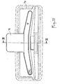
- This OLIVIER nozzle has a plastic casing 1, on top of which is mounted a pivoting suction pipe 2, which opens into a well 3 molded with the casing.
- a metal soleplate 4 is fixed under this housing by means of screws 5 and defines therewith a slot 6 through which a retractable peripheral brush 7 can project.
- two longitudinal channels 8 and 9 are hollowed out, separated by a bead 10 which does not, however, quite reach the sliding surface of said sole so that a small leak can occur between the two channels.
- the anterior channel 8 is substantially rectilinear, but its section decreases from the middle zone where a window 11 is provided, towards the ends where it opens out on the sides by passages 12 and 13.
- the posterior channel 9 is shaped as an arc trapezoidal plane in the middle core of which is formed a window 14, its branches 15, 16 diverging forward and being closed at their free ends.
- the windows 11 and 14 separated by the bead 10 open into the well 3 of the housing 1 and then communicate with the pivoting tube 2, which makes it possible to establish under the nozzle by the channels 8 and 9 a suction suitable for normal cleaning.
- narrow wire strippers 17 and 18 are fixed permanently, for example by gluing, in recesses formed in hollow on a part of the length of the sole 4, in anterior and posterior margins. These plates are covered by a fabric with oriented fibers and they are positioned so that said fibers are directed towards the windows 11 and 14.
- the sole 24 has two longitudinal channels 25 and 26 substantially rectilinear separated by two bead elements 30 between which is formed a passage 31 whose upper horizontal wall is located substantially at the same level as that of the channels.
- a window 32 is provided in this sole and extends across the anterior channel 26 as far as the passage 31, just reaching the posterior channel 25.
- German patent application SCHWAB n ° 2 100 465 describes a household material to tear off carpets, rugs, or other, the son, the hairs ... which are hung there and swallow them.
- This equipment can be a mechanical broom with one or two rotating brushes or a vacuum cleaner nozzle.
- the broom or nozzle is equipped under its sliding surface with two upholstery covered with the aforementioned oriented fiber fabric.
- these padding are arranged along the reception openings; in the case of a brush with a brush, the padding is located on either side of the longitudinal opening through which this brush intervenes; in the case of a brush with two brushes, the padding is placed between the longitudinal intervention openings of said brushes; in the case of a suction nozzle, the upholstery is arranged on either side of the very deep longitudinal opening which is connected to the suction pipe.
- the inclined fibers of one of the upholstery are directed towards the front and those of the other upholstery towards the rear, the location of said upholstery being such that said fibers are at the same time directed towards the 'common opening or both openings.
- a SCHWAB suction nozzle thus equipped has already been used commercially, which has made it possible to highlight its advantages and disadvantages.
- a first drawback of the SCHWAB material lies in the abnormal wear of the carpets if the use is prolonged, as well as in the poor aspiration of the torn wires or hairs and of the dust incorporated in these carpets. Therefore, it is necessary to have both SCHWAB equipment and a known nozzle of the aforementioned type, the former being used rarely only to carry out the extraction of threads and hair, when they are in relatively large quantity, outside carpets, rugs or the like, while the second is used to remove dust from all floors including carpets.
- a second drawback of the SCHWAB nozzle is that it resists movement too strongly, so that its operation is tiring and painful, which can lead users to give up their use. Moreover, demonstrators are well aware of this drawback and to remedy it, they place the mat to be treated in height so that the handle of the material is less inclined than in normal use, which considerably facilitates the maneuver.
- the object of the present invention is to remedy these drawbacks by improving a known nozzle of the aforementioned type or of another type reproducing its characteristics. It is simply necessary that the sole has at least two longitudinal suction channels communicating with the suction pipe by at least two openings constituted by two horizontal windows or at least one horizontal window and a vertical passage.
- At least one removable blade carrying a fiber-pulling fabric oriented is intended, when the squeegee is used as a suction puller, to be housed in the suction channel or channels selected from those presented by the sole, partially closing at least the corresponding opening, this blade being positioned so that the fibers of the fabric are oriented towards the opening left free and point at rest substantially at the level of the sliding surface of said sole, the selected channel or channels are, when the nozzle is used only for suction, released so that the suction can spread there from at least the corresponding opening.
- the blade or blades are removable and fixed in a removable manner, in the position of use, in the selected channel.
- the blade or blades are retractable and connected to a rationing mechanism integrated in the nozzle and controlled by at least one external operating member, such as a pedal, a push button or the like, this mechanism moving the blade (s) between two positions and holding them in place in these two positions which are constituted by the aforementioned position of use in which the blade (s) are lowered in the channel (s) and by a non-use position in which the or the blades are raised to form the bottom of the channel or channels whose flanges seal around the said blade or blades.
- a rationing mechanism integrated in the nozzle and controlled by at least one external operating member, such as a pedal, a push button or the like
- the improved nozzle of the invention extracts the wires and hairs from the carpets with remarkable efficiency, comparable to that of SCHWAB equipment. And when the wire stripper blade is removed or retracted, the improved nozzle of the invention works normally to remove dust on all floors, since in fact it corresponds to one of the aforementioned known nozzles without any modification. Standardized tests have shown that the dust removal rate is substantially the same in both cases: with or without a blade, it being understood that with the blade the hairs or the wires are also removed.
- the wire stripping blade is capable of being housed without play in the posterior channel, so that the pulling of the wires or of the hairs takes place when the crevice is pushed forward.
- This blade can be shaped as a trapezoidal arc, its lateral branches diverging forwards from the middle branch intended to partially close at least the window of the corresponding channel.
- Said blade can also be rectilinear and optionally provided with a positioning means so that the fibers are well directed.
- the sole has three channels of which at least the two marginal open out into two windows respectively, the wire stripper blade being capable of being housed in the median channel.
- the fibers of the blade can all be directed towards the anterior channel or the posterior channel so that the pulling of the wires or hairs takes place when the squeegee is pushed forward or respectively pulled back.
- the blade can also have two contiguous longitudinal strips of wire-stripping fabric, the fibers of one strip being directed towards the posterior channel and the fibers of the other strip being directed towards the anterior channel so that the squeegee pulls the wires forward and reverse.
- the blade when it is removable can be provided with a posterior extension fitted into a recess in the sole and projecting rearward to allow disassembly of said blade.
- Another type of support can be used to receive the strip of wire-stripping fabric. It can be a removable cap capable of being fitted onto the housing and being clipped therein to cover at least the suction channel opposite which the wire stripper strip is located and make it substantially inoperative, this cap having at least one light facing the other channel or channels to leave them free over at least part of their extent.
- the removable wire puller blade whether straight or arched in the shape of a trapezoid, has at least one protruding rib intended to be fitted with soft clamping in the corresponding window to form a removable fixing.
- the rib can be shaped like a U and then cooperates with a flange extending from the sole which delimits the window considered.
- the blade when it is retractable, may be provided with balusters crossing the bottom of the corresponding channel and guided 'in translation in the sheaths of the housing, this blade cooperating, on the one hand, with at least one spring bearing on the sole to tend to push it upwards and , on the other hand, with an actuating finger integral with a sleeve mounted to rotate around the tubing and provided with two pedals located on the sides.
- a removable blade 19 ( Figure 3) of plastic, rigid cardboard or other is shaped in correspondence with the arcuate channel 9 to get there fit together and is coated on its visible face at least with a thread-pulling fabric 20, the oriented fibers of which are directed towards the window 11.
- the blade 19 covers the window 14 and for its maintenance, independently of that exerted by the suction through this window, its nesting in the channel 9 is carried out without play and even with a slight tightening. In this position where the blade fits into a channel, the fibers at rest of the fabric 20 point at substantially the same level as the sliding surface of the sole 4.
- a rib 21 can be formed projecting from the blade and clipped into the window 14.
- the rib 21 is U-shaped and fits into a re-entrant flange 22 of the sole 4 delimiting the window 14, the flange covering the well 3. As shown in FIG. 4, the height of the rib 21 is determined so that it does not oppose the pivoting of the tube 2.
- the disassembly of the blade 19 is very easy since it suffices to slide a thin tool, such as a knife, a screwdriver ... into the slot 23 ( Figure 4) formed between this blade and the flange 22 of the window 14 contiguous to the wire puller plate 17 and to lever.
- the first embodiment applies whether or not the nozzle has a brush 7 and that the tube 2 is pivotable or else fixed. The same is true for the other embodiments described in the following.
- a wire stripping blade 29 known as rectilinear, the shape of which is symmetrical with respect to its median longitudinal axis 27 perpendicular to the direction of advance, is housed in the channel 25 and closes the vertical part of the passage 31 but not the window 32.
- this blade has two "keying pins" 33 located asymmetrically with respect to the central axis of advancement 28 of the nozzle and intended to be engaged in holes in the sole.
- the sole 24 is similar to the previous one except that the window 32 also extends across the channel 25.
- the sole 24 then cooperates with a wire stripper blade 39 which resembles the blade 29 according to FIG. 5, the only difference being that it has an advanced middle part 40 intended to take place in the passage 31 between the bead elements 30 and to partially close the window 32.
- the bead elements 30 can be relatively short, which increases the length of the passage 31, and the window 32 can partly open at less in the channel 25.
- the removable blade 29 remains effective when it is mounted and the squeegee also when it is disassembled.
- the nozzle comprises a sole 44 with three channels combining those of the soles 4 and 24.
- the channels 8 and 9 of the sole 4 separated by the continuous bead 10, thus that the arcuate blade 19 closing the window 14 of the channel 9 and fixed removably by means of the rib 21 centered in said window.
- the channel 8 resembles that of the squeegee 24 and communicates with the channel 26 through the passage 31 extending between the bead elements 30.
- the window 11 of the sole 4 is located in the intermediate channel 8 of the sole 44, but extends into the passage 31 as in the sole 24.
- the sole 54 comprises, like the sole 44, three channels 55, 56 and 57, with the only differences that these channels are rectilinear and that the blade 59 is housed in the intermediate channel 56.
- the marginal channel 55 includes the window 14 and is separated from the intermediate channel 56 by the continuous bead 10.
- the marginal channel 57 is separated from the intermediate channel 56 by the bead elements 30 extending on either side of the passage 31, the window 32 being formed in said channel 56, the passage 31 and part of the width of the channel 57.
- the blade 59 can be coated with a single strip of wire-stripping fabric 20a or 20b, the fibers of which are inclined respectively forward or backward to pull the wires or the hairs when the squeegee is pushed (arrow f1) or pulled (arrow f2); the blade 59 is provided with a fixing rib 21 and if the user is attentive, it can be mounted with the fabric positioned according to 20a or 20b by simple inversion with the U-shaped rib open forwards or backwards ; if the nozzle is equipped with two blades 59 with bands 20a and 20b respectively, these blades must be provided with "coding pins" 33; this arrangement is particularly advantageous for the user who can thus intervene according to his usual reflexes,
- the soleplate 64 comprises three rectilinear channels 65, 66 and 67 into which open suction windows 71, 72 and 73 respectively and which are separated by continuous beads 74 and 75.
- a wire stripper blade 69 is mounted in the intermediate channel 66 in a removable manner by means of the rib 21 centered in the window 72.
- This blade can be coated, as in the fourth embodiment, with strips 20a or 20b and optionally provided with "coding pins" 33 not shown.
- the blade 59 can tear off the wires when the nozzle is moved in forward and reverse directions respectively. The torn off wires can then be swallowed in both directions by the squeegee.
- this blade 69 with symmetrical bands 68, 70 can be narrower and mounted in the intermediate channel 56 of the fourth embodiment according to FIG. 8. In this case, the coding pins 33 are unnecessary.
- the blades 19, 29, 39 and 59 and 69 described in the foregoing can be removed by means of a thin tool slid into the slot 23 ( Figure 4).
- extension 76 of the blade can also be thanks to an extension 76 of the blade.
- This extension is shown for the blade 19 in Figures 10 and 11. It extends in a recess 77 of the sole 4 and protrudes behind it.
- said extension 76 either directly with the foot 78 or by means of the peripheral brush 79 of the squeegee that the pedal operated by the foot protrudes around the sole, the blade is disassembled.
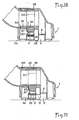
- the interlocking blade 19, 29, 39 or 69 which is intended to support a thread-pulling fabric 20, to close one of the suction channels 9, 25, 56 or 66 and to at least partially close the corresponding window 14, 32 or 72, can be replaced, as is apparent from the sixth embodiment illustrated in FIG. 12 by a cover 80 preferably made of molded plastic.
- the latter then has a flange 81 capable of being fitted onto the squeegee housing 1 and of being fixed there elastically by means of hooks 82. In this position, the bottom 83 of the cover is applied against the sole 4.
- the cover 80 is adapted to the embodiment according to FIGS. 1 to 4.
- the bottom 83 comprises, on the one hand, a bulge 84 intended to be housed in the channel 9 of the sole and to close the window 14 and, on the other hand, a lumen 85 located opposite the channel 8.
- the fabric 20 with oriented fibers is fixed in an external depression of the bulge 84.
- a boss 86 protrudes rearward to allow disassembly at the foot of the cap 66.
- the sole has three channels, two of these can be filled with fabrics 20 made removable.
- the fabrics can be fixed under the cover 80 or else under blades of the aforementioned type but which are connected together by crosspieces extending above the sliding surface of the sole 4 in passages connecting the corresponding channels.
- the wire stripper blade may retract into the housing 1 by upward movement and constitute the bottom of the channel in which it is mounted when the nozzle is used to remove the dust (position shown in solid lines in FIGS. 15 and 18), said blade closing off said channel and substantially flush with the sliding surface of sole 94 when the nozzle is used. used to tear off and swallow the wires (position shown in phantom in said Figures 15 and 18).
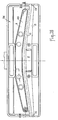
- FIGS. 13 to 15 Such a retractable blade 89 is illustrated in FIGS. 13 to 15 for a seventh embodiment of the nozzle and in FIGS. 16 to 18 for an alternative embodiment.
- the sole 94 of the squeegee delimits, like that of the first according to Figures 1 to 4, two channels 8 and 9 of the same shape.
- the anterior channel 8 opens on the sides by extreme passages 12 and 13 and communicates with the suction pipe through the window 11.
- the channels 8 and 9 are separated from each other by bead elements 30 between which the central passage 31 is formed.
- This vertical passage establishes communication between the anterior canal 8 and the posterior canal 9, which is free from a horizontal window.
- the upper wall of the posterior channel 9 is constituted by the blade 89 in the high position illustrated in solid lines in FIGS. 14, 15 and 17, 18.
- the depression propagates from the window 11 directly in the anterior canal 8 and, through the passage 31, into the posterior canal 9.
- the channels 8 and 9 are separated from each other by a continuous bead 10.
- vertical passages are constituted by lights 87 cut by the walls of the bead 10 above the edge 88 thereof; this edge is therefore not interrupted over the entire length of the squeegee and therefore completely fulfills its role of "massaging" the toupees of the carpet; despite this, the passages 87 establish communication between the anterior channel 8 and its window 11 with the posterior channel 9 when the blade 89 is raised in the high position.
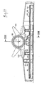
- the blade 89 cooperates with an actuation mechanism integrated in the nozzle and allowing this blade to be moved between the two positions above by maintaining it positively at least in the low position of wire puller.
- the blade 89 is integral with two vertical posts 90 passing through the bottom 91 of the channel 9 of the sole 94, these posts being guided in translation above in sheaths 92 molded with the housing.
- the blade can therefore move parallel to itself.
- the actuating mechanism comprises, for the elastic return of said blade to the high retraction position shown in solid lines, two springs 93.
- This blade is integral with two hollow rods 95 crossing the bottom 91 of the channel 9 and projecting at -above.
- Each spring 93 is threaded onto the projecting part of the corresponding rod and is interposed between this bottom 91 and a flange 96 attached to the free end of the rod in question.
- the actuation mechanism comprises, for the positive actuation of said blade 89 towards the low position of wire puller shown in phantom, a finger 97 integral with a sleeve 98 mounted rotating around a geometric axis of the housing 1 extending orthogonally to the longitudinal direction of said blade.
- the suction pipe 2 is stepped and rotatably mounted in a tubular part 99 also stepped in the housing 1 so as to provide between them a free space in which the sleeve 98 is itself mounted rotating.
- the part 99 of the suction pipe is immobilized in translation by an elastic ring 100 and the sleeve 98 by the finger 97 passing through a lumen 101 of said part.
- said sleeve 98 is integral with pedals 102 and 103 located on the sides. When the pedal 103 is depressed and the pedal 102 protrudes (position shown in solid lines in FIG. 14 or 17), the finger 97 does not urge the blade 89 and the latter occupies the high retraction position.
- the blade 89 is integral with an ascending cam 104 intended to cooperate with the finger actuation 97 during its pivoting.
- the actuation mechanism can cooperate with two or more wire stripping blades.
- the retraction can be applied to embodiments in which the blade is removable.
Landscapes
- Engineering & Computer Science (AREA)
- Mechanical Engineering (AREA)
- Nozzles For Electric Vacuum Cleaners (AREA)
- Manufacture Of Alloys Or Alloy Compounds (AREA)
Claims (19)
Priority Applications (1)
| Application Number | Priority Date | Filing Date | Title |
|---|---|---|---|
| AT87401071T ATE55232T1 (de) | 1986-05-30 | 1987-05-13 | Staubsaugermundstueck mit fadenfangborsten. |
Applications Claiming Priority (2)
| Application Number | Priority Date | Filing Date | Title |
|---|---|---|---|
| FR8607812 | 1986-05-30 | ||
| FR8607812A FR2599236B1 (fr) | 1986-05-30 | 1986-05-30 | Suceur d'aspirateur avec arrache-fils. |
Publications (2)
| Publication Number | Publication Date |
|---|---|
| EP0248695A1 EP0248695A1 (de) | 1987-12-09 |
| EP0248695B1 true EP0248695B1 (de) | 1990-08-08 |
Family
ID=9335840
Family Applications (1)
| Application Number | Title | Priority Date | Filing Date |
|---|---|---|---|
| EP87401071A Expired - Lifetime EP0248695B1 (de) | 1986-05-30 | 1987-05-13 | Staubsaugermundstück mit Fadenfangborsten |
Country Status (6)
| Country | Link |
|---|---|
| US (1) | US4888852A (de) |
| EP (1) | EP0248695B1 (de) |
| AT (1) | ATE55232T1 (de) |
| CA (1) | CA1282916C (de) |
| DE (1) | DE3764191D1 (de) |
| FR (1) | FR2599236B1 (de) |
Families Citing this family (34)
| Publication number | Priority date | Publication date | Assignee | Title |
|---|---|---|---|---|
| FR2642637B1 (fr) * | 1989-02-09 | 1994-10-07 | Olivier Ets Georges | Suceur d'aspirateur pour tapis ou moquettes, sols durs secs et sols durs mouilles |
| FR2653654B1 (fr) * | 1989-10-31 | 1992-02-14 | Olivier Ets Georges | Boitier a raccord tournant pour suceur d'aspirateur. |
| FR2678818B1 (fr) * | 1991-07-11 | 1995-07-13 | Olivier Ets Georges | Dispositif arrache-fils pour semelle de suceur d'aspirateur. |
| DE4201596C2 (de) * | 1992-01-22 | 2001-07-05 | Gerhard Kurz | Bodendüse für Staubsauger |
| DE4304682C2 (de) * | 1993-02-16 | 1996-01-25 | Wessel Werk Gmbh | Staubsaugerdüse |
| DE4304681C2 (de) * | 1993-02-16 | 1996-06-05 | Wessel Werk Gmbh | Einteilige Staubsaugerdüse |
| DE4406156A1 (de) * | 1994-02-25 | 1995-08-31 | Licentia Gmbh | Saugmundstück für Staubsauger |
| US5557823A (en) * | 1995-05-26 | 1996-09-24 | Jma & Associates | Vacuum cleaner attachment |
| DE19602723C2 (de) * | 1996-01-26 | 2001-04-19 | Gerhard Kurz | Vorrichtung zum Betrieb eines Staubsaugers |
| GB0023732D0 (en) * | 2000-09-28 | 2000-11-08 | Notetry Ltd | A floor tool |
| US6588058B2 (en) * | 2001-03-20 | 2003-07-08 | Roger P. Vanderlinden | Large area surface cleaning tool |
| US6584640B2 (en) * | 2001-03-20 | 2003-07-01 | Roger P. Vanderlinden | Large area surface cleaning tool for suctioning both dust and debris |
| DE10241492B4 (de) * | 2002-09-07 | 2006-11-02 | Wessel-Werk Gmbh | Bodendüse für Staubsauger |
| DE10241491B4 (de) * | 2002-09-07 | 2006-10-26 | Wessel-Werk Gmbh | Bodendüse für Staubsauger |
| KR100613102B1 (ko) * | 2004-07-01 | 2006-08-17 | 삼성광주전자 주식회사 | 흡입구조립체와 이를 구비한 진공청소기 |
| DE202005020507U1 (de) * | 2005-12-20 | 2006-04-13 | Alfred Kärcher Gmbh & Co. Kg | Bodendüse für Staubsauger |
| DE102006060855B4 (de) * | 2006-12-22 | 2013-08-01 | Wessel-Werk Gmbh | Bodendüse für Staubsauger |
| KR20090017870A (ko) * | 2007-08-16 | 2009-02-19 | 삼성광주전자 주식회사 | 헤어제거유닛을 구비한 진공청소기용 흡입브러시 |
| CN106079159A (zh) | 2008-06-26 | 2016-11-09 | 谐和能源有限责任公司 | 废弃物存储一体化的系统与方法 |
| GB2468514B (en) * | 2009-03-12 | 2012-07-11 | Dyson Technology Ltd | A surface-treating head |
| AU2010201002B2 (en) * | 2009-03-20 | 2014-06-26 | Bissell Inc. | Vacuum accessory tool |
| EP3108786B1 (de) * | 2009-06-17 | 2019-09-18 | Dyson Technology Limited | Werkzeug für eine oberflächenbehandlungsvorrichtung |
| EP2453780B1 (de) * | 2009-07-16 | 2013-11-13 | Dyson Technology Limited | Kopf zur oberflächenbehandlung |
| GB0912356D0 (en) * | 2009-07-16 | 2009-08-26 | Dyson Technology Ltd | A surface treating head |
| GB2479530B (en) * | 2010-04-12 | 2012-07-18 | Ponnampalam Shanmugaratnam | Vacuum cleaner hair removal pads |
| CN107254337B (zh) | 2011-06-03 | 2020-02-07 | 谐和能源有限责任公司 | 由废物材料制备过程设计燃料原料的系统和方法 |
| GB2496663B (en) * | 2011-11-18 | 2014-07-30 | Dyson Technology Ltd | A cleaner head |
| US9126204B1 (en) | 2013-01-24 | 2015-09-08 | Wm Intellectual Property Holdings L.L.C. | Process and system for producing engineered fuel |
| CN104013356A (zh) * | 2014-05-09 | 2014-09-03 | 苏州艾利欧电器有限公司 | 一种单风道地刷 |
| CN104013355A (zh) * | 2014-05-09 | 2014-09-03 | 苏州艾利欧电器有限公司 | 一种多风道地刷 |
| US10400188B2 (en) | 2015-06-24 | 2019-09-03 | Wm Intellectual Property Holdings, L.L.C. | Process and system for producing engineered fuel |
| DE102015113460A1 (de) * | 2015-08-14 | 2017-02-16 | Vorwerk & Co. Interholding Gmbh | Bodendüse für ein Reinigungsgerät, insbesondere für einen Staubsauger |
| CN107126151A (zh) * | 2017-07-12 | 2017-09-05 | 小狗电器互联网科技(北京)股份有限公司 | 吸尘器地刷和吸尘器 |
| US11607101B2 (en) | 2019-08-05 | 2023-03-21 | Bissell Inc. | Vacuum cleaner accessory tool |
Family Cites Families (12)
| Publication number | Priority date | Publication date | Assignee | Title |
|---|---|---|---|---|
| US2703903A (en) * | 1949-12-22 | 1955-03-15 | Electrolux Ab | Combination suction cleaner nozzle and brush member |
| FR1085915A (fr) * | 1953-03-24 | 1955-02-08 | Ustensile de nettoyage | |
| US2893048A (en) * | 1955-04-21 | 1959-07-07 | Health Mor Inc | Suction cleaner nozzle construction for cleaning cotton rugs |
| DE1072957B (de) * | 1958-07-04 | 1960-01-14 | WiIdbergerhütte Hans Wessel (Bez. Köln) | Aus einer Borstenträgerplattc und aus einer oder mehreren Borstenschienen bestehende Bürste |
| DE2024616B2 (de) * | 1970-05-20 | 1971-08-05 | Schwab geb Gitschel, Hilde, Zem bold, Heinz, 4000 Dusseldorf | Vorrichtung zum saeubern von textilien |
| DE2100465A1 (de) * | 1971-01-07 | 1972-07-20 | Schwab Geb Gitschel H | Fadenaufnehmer für eine Vorrichtung zum Säubern von Textilien |
| GB1340466A (en) * | 1971-05-12 | 1973-12-12 | Allstar Verbrauchsgueter Gmbh | Nozzle for vacuum cleaner |
| DE2220815A1 (de) * | 1972-04-27 | 1973-11-08 | Hans Wessel | Staubsaugerduese fuer teppich- und bodenreinigung |
| US3820189A (en) * | 1972-12-11 | 1974-06-28 | E Roth | Brush adaptor for vacuuming |
| DE7237505U (de) * | 1973-11-14 | 1974-03-21 | Wessel H | Staubsaugerdüse mit Fadenaufnehmer |
| US4319379A (en) * | 1980-04-29 | 1982-03-16 | Carrigan William J | Pickup |
| DE3025977C2 (de) * | 1980-07-09 | 1985-06-13 | Allstar Verbrauchsgüter GmbH & Co KG, 6000 Frankfurt | Mundstück für Staubsaugerdüsen |
-
1986
- 1986-05-30 FR FR8607812A patent/FR2599236B1/fr not_active Expired
-
1987
- 1987-05-13 AT AT87401071T patent/ATE55232T1/de not_active IP Right Cessation
- 1987-05-13 EP EP87401071A patent/EP0248695B1/de not_active Expired - Lifetime
- 1987-05-13 DE DE8787401071T patent/DE3764191D1/de not_active Expired - Fee Related
- 1987-05-27 US US07/054,589 patent/US4888852A/en not_active Expired - Fee Related
- 1987-05-28 CA CA000538275A patent/CA1282916C/en not_active Expired - Lifetime
Also Published As
| Publication number | Publication date |
|---|---|
| EP0248695A1 (de) | 1987-12-09 |
| FR2599236A1 (fr) | 1987-12-04 |
| US4888852A (en) | 1989-12-26 |
| CA1282916C (en) | 1991-04-16 |
| FR2599236B1 (fr) | 1989-03-10 |
| DE3764191D1 (de) | 1990-09-13 |
| ATE55232T1 (de) | 1990-08-15 |
Similar Documents
| Publication | Publication Date | Title |
|---|---|---|
| EP0248695B1 (de) | Staubsaugermundstück mit Fadenfangborsten | |
| JPH05261041A (ja) | 真空掃除機用床ノズル | |
| FR2913325A1 (fr) | Aspirateur et procede pour enlever des poils d'une surface qui en est chargee | |
| EP0382598B1 (de) | Saugmundstück für Teppiche oder für trockene und nasse Hartoberflächen-Moketts | |
| EP1173085B1 (de) | Staubsaugermundstück mit abstreifleiste | |
| WO2002085174A1 (fr) | Embout pour aspirateur | |
| US20100236019A1 (en) | Nozzle for a floor cleaning device | |
| FR2829681A1 (fr) | Dispositif de nettoyage de sol | |
| EP2760325A1 (de) | Staubsaugerkopf | |
| EP1045660B1 (de) | Staubsaugermundstück | |
| EP0734213B1 (de) | Bürste mit einem kamm | |
| US8418313B1 (en) | Power cord protection system for a floor cleaner | |
| FR2729842A1 (fr) | Suceur d'aspirateur | |
| EP1488726B1 (de) | Staubsaugerdüse | |
| EP1488728B1 (de) | Staubsaugerdüse | |
| KR101253245B1 (ko) | 스팀청소기 | |
| EP3834691A1 (de) | Reinigungskopf ausgestattet mit einem abnehmbaren reinigungselement | |
| CA3115133A1 (fr) | Balai de nettoyage de sol a fonction electrique | |
| EP0522968B1 (de) | Fadenaufnehmer einer Staubsaugerdüse | |
| EP3313251A1 (de) | Staubsaugerdüse und staubsauger mit einer staubsaugerdüse | |
| EP1488727B1 (de) | Saugdüse eines Staubsaugers | |
| EP1369074A1 (de) | Staubsaugersaugdüse mit Abstreifvorrichtung | |
| KR101354675B1 (ko) | 진공청소기의 흡입장치 | |
| FR2665071A1 (fr) | Balai-brosse avec serpilliere a essorage integre. | |
| JPH06343586A (ja) | 真空掃除機用吸込具 |
Legal Events
| Date | Code | Title | Description |
|---|---|---|---|
| PUAI | Public reference made under article 153(3) epc to a published international application that has entered the european phase |
Free format text: ORIGINAL CODE: 0009012 |
|
| AK | Designated contracting states |
Kind code of ref document: A1 Designated state(s): AT BE CH DE ES FR GB IT LI NL SE |
|
| 17P | Request for examination filed |
Effective date: 19880505 |
|
| 17Q | First examination report despatched |
Effective date: 19890817 |
|
| GRAA | (expected) grant |
Free format text: ORIGINAL CODE: 0009210 |
|
| AK | Designated contracting states |
Kind code of ref document: B1 Designated state(s): AT BE CH DE ES FR GB IT LI NL SE |
|
| PG25 | Lapsed in a contracting state [announced via postgrant information from national office to epo] |
Ref country code: IT Free format text: LAPSE BECAUSE OF FAILURE TO SUBMIT A TRANSLATION OF THE DESCRIPTION OR TO PAY THE FEE WITHIN THE PRESCRIBED TIME-LIMIT;WARNING: LAPSES OF ITALIAN PATENTS WITH EFFECTIVE DATE BEFORE 2007 MAY HAVE OCCURRED AT ANY TIME BEFORE 2007. THE CORRECT EFFECTIVE DATE MAY BE DIFFERENT FROM THE ONE RECORDED. Effective date: 19900808 Ref country code: NL Effective date: 19900808 Ref country code: SE Free format text: THE PATENT HAS BEEN ANNULLED BY A DECISION OF A NATIONAL AUTHORITY Effective date: 19900808 Ref country code: AT Effective date: 19900808 |
|
| REF | Corresponds to: |
Ref document number: 55232 Country of ref document: AT Date of ref document: 19900815 Kind code of ref document: T |
|
| REF | Corresponds to: |
Ref document number: 3764191 Country of ref document: DE Date of ref document: 19900913 |
|
| GBT | Gb: translation of ep patent filed (gb section 77(6)(a)/1977) | ||
| PG25 | Lapsed in a contracting state [announced via postgrant information from national office to epo] |
Ref country code: ES Free format text: LAPSE BECAUSE OF FAILURE TO SUBMIT A TRANSLATION OF THE DESCRIPTION OR TO PAY THE FEE WITHIN THE PRESCRIBED TIME-LIMIT Effective date: 19901119 |
|
| NLV1 | Nl: lapsed or annulled due to failure to fulfill the requirements of art. 29p and 29m of the patents act | ||
| PG25 | Lapsed in a contracting state [announced via postgrant information from national office to epo] |
Ref country code: BE Effective date: 19910531 |
|
| PLBE | No opposition filed within time limit |
Free format text: ORIGINAL CODE: 0009261 |
|
| STAA | Information on the status of an ep patent application or granted ep patent |
Free format text: STATUS: NO OPPOSITION FILED WITHIN TIME LIMIT |
|
| 26N | No opposition filed | ||
| BERE | Be: lapsed |
Owner name: ETS GEORGES OLIVIER Effective date: 19910531 |
|
| PGFP | Annual fee paid to national office [announced via postgrant information from national office to epo] |
Ref country code: GB Payment date: 19940506 Year of fee payment: 8 |
|
| PGFP | Annual fee paid to national office [announced via postgrant information from national office to epo] |
Ref country code: CH Payment date: 19940516 Year of fee payment: 8 |
|
| PGFP | Annual fee paid to national office [announced via postgrant information from national office to epo] |
Ref country code: DE Payment date: 19940526 Year of fee payment: 8 |
|
| PGFP | Annual fee paid to national office [announced via postgrant information from national office to epo] |
Ref country code: FR Payment date: 19940531 Year of fee payment: 8 |
|
| PG25 | Lapsed in a contracting state [announced via postgrant information from national office to epo] |
Ref country code: GB Effective date: 19950513 |
|
| PG25 | Lapsed in a contracting state [announced via postgrant information from national office to epo] |
Ref country code: LI Effective date: 19950531 Ref country code: CH Effective date: 19950531 |
|
| GBPC | Gb: european patent ceased through non-payment of renewal fee |
Effective date: 19950513 |
|
| REG | Reference to a national code |
Ref country code: CH Ref legal event code: PL |
|
| PG25 | Lapsed in a contracting state [announced via postgrant information from national office to epo] |
Ref country code: DE Effective date: 19960201 |
|
| PG25 | Lapsed in a contracting state [announced via postgrant information from national office to epo] |
Ref country code: FR Effective date: 19960229 |
|
| REG | Reference to a national code |
Ref country code: FR Ref legal event code: ST |
|
| REG | Reference to a national code |
Ref country code: FR Ref legal event code: ST |