EP0248695B1 - Vacuum cleaner nozzle with thread catching bristles - Google Patents
Vacuum cleaner nozzle with thread catching bristles Download PDFInfo
- Publication number
- EP0248695B1 EP0248695B1 EP87401071A EP87401071A EP0248695B1 EP 0248695 B1 EP0248695 B1 EP 0248695B1 EP 87401071 A EP87401071 A EP 87401071A EP 87401071 A EP87401071 A EP 87401071A EP 0248695 B1 EP0248695 B1 EP 0248695B1
- Authority
- EP
- European Patent Office
- Prior art keywords
- blade
- suction head
- channel
- channels
- thread
- Prior art date
- Legal status (The legal status is an assumption and is not a legal conclusion. Google has not performed a legal analysis and makes no representation as to the accuracy of the status listed.)
- Expired - Lifetime
Links
Images


Classifications
-
- A—HUMAN NECESSITIES
- A47—FURNITURE; DOMESTIC ARTICLES OR APPLIANCES; COFFEE MILLS; SPICE MILLS; SUCTION CLEANERS IN GENERAL
- A47L—DOMESTIC WASHING OR CLEANING; SUCTION CLEANERS IN GENERAL
- A47L9/00—Details or accessories of suction cleaners, e.g. mechanical means for controlling the suction or for effecting pulsating action; Storing devices specially adapted to suction cleaners or parts thereof; Carrying-vehicles specially adapted for suction cleaners
- A47L9/02—Nozzles
- A47L9/06—Nozzles with fixed, e.g. adjustably fixed brushes or the like
- A47L9/0633—Nozzles with fixed, e.g. adjustably fixed brushes or the like with retractable brushes, combs, lips or pads
- A47L9/064—Nozzles with fixed, e.g. adjustably fixed brushes or the like with retractable brushes, combs, lips or pads actuating means therefor
- A47L9/0653—Nozzles with fixed, e.g. adjustably fixed brushes or the like with retractable brushes, combs, lips or pads actuating means therefor with mechanical actuation, e.g. using a lever
Abstract
Description
La présente invention concerne un suceur d'aspirateur à au moins deux canaux longitudinaux aspirants.The present invention relates to a vacuum cleaner nozzle with at least two longitudinal suction channels.
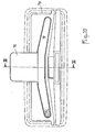
Un tel suceur est exploité par la demanderesse et décrit ci-après en se référant aux figures 1 à 4 du dessin annexé. Ce suceur OLIVIER comporte un boîtier 1 en matière plastique, sur le dessus duquel est montée une tubulure pivotante d'aspiration 2, laquelle débouche dans un puits 3 venu de moulage avec le boîtier.Such a nozzle is operated by the applicant and described below with reference to Figures 1 to 4 of the accompanying drawing. This OLIVIER nozzle has a
Une semelle métallique 4 est fixée sous ce boîtier au moyen de vis 5 et délimite avec celui-ci une fente 6 à travers laquelle peut faire saillie une brosse périphérique escamotable 7.A
Dans la semelle, sont formés en creux deux canaux longitudinaux 8 et 9 séparés par un bourrelet 10 qui n'atteint cependant pas tout à fait la surface de glissement de ladite semelle afin qu'une faible fuite puisse se produire entre les deux canaux.In the sole, two
Le canal antérieur 8 est sensiblement rectiligne, mais sa section décroît de la zone médiane où une fenêtre 11 est ménagée, vers les extrémités où il débouche sur les côtés par des passages 12 et 13. Par contre, le canal postérieur 9 est conformé en arc trapézoïdal plan dans l'âme médiane duquel est ménagée une fenêtre 14, ses branches 15, 16 divergeant vers l'avant et étant fermées à leurs extrémités libres.The
Les fenêtres 11 et 14 séparées par le bourrelet 10 débouchent dans le puits 3 du boîtier 1 et communiquent alors avec la tubulure pivotante 2, ce qui permet d'établir sous le suceur par les canaux 8 et 9 une succion appropriée à un nettoyage normal.The
Par ailleurs, des plaquettes arrache-fils étroites 17 et 18 sont fixées à demeure, par collage par exemple, dans des évidements formés en creux sur une partie de la longueur de la semelle 4, en marges antérieure et postérieure. Ces plaquettes sont recou- vertes par un tissu à fibres orientées et elles sont positionnées pour que lesdites fibres soient dirigées vers les fenêtres 11 et 14.Furthermore,
Un autre suceur de ce type fait l'objet de la demande de brevet allemand WESSEL n° 2 220 815. Seuls les éléments de la semelle qui distinguent le suceur WESSEL du suceur OLIVIER sont décrits ci-après en se référant à la figure 5 du dessin annexé. La semelle 24 présente deux canaux longitudinaux 25 et 26 sensiblement rectilignes séparés par deux éléments de bourrelet 30 entre lesquels est ménagé un passage 31 dont la paroi horizontale supérieure est située sensiblement au même niveau que celle des canaux. Une fenêtre 32 est ménagée dans cette semelle et s'étend en travers du canal antérieur 26 jusque dans le passage 31 en atteignant tout juste le canal postérieur 25.Another nozzle of this type is the subject of German patent application WESSEL No. 2,220,815. Only the elements of the sole which distinguish the nozzle WESSEL from the nozzle OLIVIER are described below with reference to FIG. 5 of the attached drawing. The sole 24 has two
Ces suceurs connus ne permettent pas d'arracher d'un tapis, d'une moquette... les produits fibreux tels que poils, fils... qui peuvent s'y trouver accrochés en quantité relativement grande après des travaux de couture ou lorsqu'un chien ou autre animal à poils a séjourné dans le local et de les aspirer.These known squeegees do not make it possible to tear from a carpet, a carpet ... the fibrous products such as pile, son ... which can be hung there in relatively large quantity after sewing work or when 'a dog or other furry animal has stayed in the room and vacuumed them.
Or, la demande de brevet allemand SCHWAB n° 2 100 465 décrit un matériel de ménage pour arracher des tapis, des moquettes, ou autres, les fils, les poils... qui s'y trouvent accrochés et les avaler. Ce matériel peut être un balai mécanique à une ou deux brosses tournantes ou une buse d'aspirateur. Le balai ou la buse est équipé sous sa surface de glissement de deux capitonnages revêtus du tissu à fibres orientées précité. Ces capitonnages sont disposés le long des ouvertures de réception ; s'il s'agit d'un balai à une brosse, les capitonnages sont situés de part et d'autre de l'ouverture longitudinale à travers laquelle cette brosse intervient ; s'il s'agit d'un balai à deux brosses, les capitonnages sont placés entre les ouvertures longitudinales d'intervention desdites brosses ; s'il s'agit d'une buse d'aspiration, les capitonnages sont disposés de part et d'autre de l'ouverture longitudinale très profonde qui est raccordée à la tubulure d'aspiration. Dans tous les cas, les fibres inclinées de l'un des capitonnages sont dirigées vers l'avant et celles de l'autre capitonnage vers l'arrière, l'emplacement desdits capitonnages étant tel que lesdites fibres se trouvent en même temps dirigées vers l'ouverture commune ou les deux ouvertures.However, the German patent application SCHWAB n ° 2 100 465 describes a household material to tear off carpets, rugs, or other, the son, the hairs ... which are hung there and swallow them. This equipment can be a mechanical broom with one or two rotating brushes or a vacuum cleaner nozzle. The broom or nozzle is equipped under its sliding surface with two upholstery covered with the aforementioned oriented fiber fabric. These padding are arranged along the reception openings; in the case of a brush with a brush, the padding is located on either side of the longitudinal opening through which this brush intervenes; in the case of a brush with two brushes, the padding is placed between the longitudinal intervention openings of said brushes; in the case of a suction nozzle, the upholstery is arranged on either side of the very deep longitudinal opening which is connected to the suction pipe. In all cases, the inclined fibers of one of the upholstery are directed towards the front and those of the other upholstery towards the rear, the location of said upholstery being such that said fibers are at the same time directed towards the 'common opening or both openings.
Une buse aspirante SCHWAB ainsi équipée a déjà été exploitée commercialement, ce qui a permis de mettre en evidence ses avantage et inconvénients.A SCHWAB suction nozzle thus equipped has already been used commercially, which has made it possible to highlight its advantages and disadvantages.
L'avantage de ce matériel réside dans son efficacité pour extraire les fils et les poils des tapis, ce que ne permettent pas autant les suceurs connus précités.The advantage of this material lies in its effectiveness in extracting the threads and hairs from carpets, which the aforementioned known nozzles do not allow as much.
Cependant, un premier inconvénient du matériel SCHWAB réside dans l'usure anormale des tapis si l'utilisation est prolongée, ainsi que dans la mauvaise aspiration des fils ou poils arrachés et des poussières incorporées dans ces tapis. Dès lors, il est nécessaire de disposer à la fois du matériel SCHWAB et d'un suceur connu du type précité, le premier étant utilisé rarement uniquement pour procéder à une extraction des fils et des poils, lorsqu'ils sont en quantité relativement importante, hors des tapis, des moquettes ou autres, tandis que le deuxième est employé pour enlever les poussières de tous les sols y compris les tapis.However, a first drawback of the SCHWAB material lies in the abnormal wear of the carpets if the use is prolonged, as well as in the poor aspiration of the torn wires or hairs and of the dust incorporated in these carpets. Therefore, it is necessary to have both SCHWAB equipment and a known nozzle of the aforementioned type, the former being used rarely only to carry out the extraction of threads and hair, when they are in relatively large quantity, outside carpets, rugs or the like, while the second is used to remove dust from all floors including carpets.
Un deuxième inconvénient du suceur SCHWAB réside dans le fait qu'il résiste trop fortement aux déplacements, de sorte que sa manoeuvre est fatigante et pénible, ce qui peut conduire les utilisateurs à renoncer à son emploi. D'ailleurs, les démonstrateurs connaissent bien cet inconvénient et pour y remédier, ils placent le tapis à traiter en hauteur pour que le manche du matériel soit moins incliné qu'en utilisation normale, ce qui facilite considérablement la manoeuvre.A second drawback of the SCHWAB nozzle is that it resists movement too strongly, so that its operation is tiring and painful, which can lead users to give up their use. Moreover, demonstrators are well aware of this drawback and to remedy it, they place the mat to be treated in height so that the handle of the material is less inclined than in normal use, which considerably facilitates the maneuver.
La présente invention a pour but de remédier à ces inconvénients en perfectionnant un suceur connu du type précité ou d'un autre type reproduisant ses caractéristiques. Il faut simplement que la semelle présente au moins deux canaux longitudinaux aspirants communiquant avec la tubulure d'aspiration par au moins deux ouvertures constituées par deux fenêtres horizontales ou au moins une fenêtre horizontale et un passage vertical.The object of the present invention is to remedy these drawbacks by improving a known nozzle of the aforementioned type or of another type reproducing its characteristics. It is simply necessary that the sole has at least two longitudinal suction channels communicating with the suction pipe by at least two openings constituted by two horizontal windows or at least one horizontal window and a vertical passage.
Conformément à l'invention, au moins une lame amovible portant un tissu arrache-fils à fibres orientées est destinée, lorsque le suceur est utilisé en arrache-fils aspirant, à venir se loger dans le ou les canaux aspirants sélectionnés parmi ceux que présente la semelle en obturant en partie au moins l'ouverture correspondante, cette lame étant positionnée pour que les fibres du tissu soient orientées vers l'ouverture laissée libre et pointent au repos sensiblement au niveau de la surface de glissement de ladite semelle, le ou les canaux sélectionnés sont, lorsque le suceur est utilisé uniquement pour aspirer, libérés pour que l'aspiration puisse s'y propager à partir d'au moins l'ouverture correspondante.According to the invention, at least one removable blade carrying a fiber-pulling fabric oriented is intended, when the squeegee is used as a suction puller, to be housed in the suction channel or channels selected from those presented by the sole, partially closing at least the corresponding opening, this blade being positioned so that the fibers of the fabric are oriented towards the opening left free and point at rest substantially at the level of the sliding surface of said sole, the selected channel or channels are, when the nozzle is used only for suction, released so that the suction can spread there from at least the corresponding opening.
Dans un cas particulier, la ou les lames sont amovibles et fixées de façon démontable, en position d'utilisation, dans le canal sélectionné.In a particular case, the blade or blades are removable and fixed in a removable manner, in the position of use, in the selected channel.
Dans un autre cas particulier, la ou les lames sont escamotables et reliées à un mécanisme d'ationnement intégré dans le suceur et commandé par au moins un organe extérieur de manoeuvre, tel qu'une pédale, un bouton-poussoir ou autre, ce mécanisme déplaçant la ou les lames entre deux positions et les maintenant en place dans ces deux positions qui sont constituées par la position d'utilisation précitée dans laquelle la ou les lames sont abaissées dans le ou les canaux et par une position de non utilisation dans laquelle la ou les lames sont relevées pour former le fond du ou des canaux dont les rebords assurent l'étanchéité autour de la ou desdites lames.In another particular case, the blade or blades are retractable and connected to a rationing mechanism integrated in the nozzle and controlled by at least one external operating member, such as a pedal, a push button or the like, this mechanism moving the blade (s) between two positions and holding them in place in these two positions which are constituted by the aforementioned position of use in which the blade (s) are lowered in the channel (s) and by a non-use position in which the or the blades are raised to form the bottom of the channel or channels whose flanges seal around the said blade or blades.
Lorsque la lame arrache-fils est en place, le suceur perfectionné de l'invention extrait les fils et les poils des tapis avec une efficacité remarquable, comparable à celle du matériel SCHWAB. Et lorsque la lame arrache-fils est enlevée ou escamotée, le suceur perfectionné de l'invention fonctionne normalement pour enlever les poussières sur tous les sols, puisqu'en fait il correspond à l'un des suceurs connus précités sans aucune modification. Les essais normalisés ont montré que le taux d'enlèvement des poussières est sensiblement le même dans les deux cas : avec ou sans lame, étant entendu qu'avec la lame les poils ou les fils sont également enlevés.When the wire stripper blade is in place, the improved nozzle of the invention extracts the wires and hairs from the carpets with remarkable efficiency, comparable to that of SCHWAB equipment. And when the wire stripper blade is removed or retracted, the improved nozzle of the invention works normally to remove dust on all floors, since in fact it corresponds to one of the aforementioned known nozzles without any modification. Standardized tests have shown that the dust removal rate is substantially the same in both cases: with or without a blade, it being understood that with the blade the hairs or the wires are also removed.
Ce résultat est remarquable et inattendu. Peut- être est-il dû à l'action "mécanique" des fibres inclinées du tissu sur les "toupets" du tapis. En tout cas, il démontre l'efficacité de ce matériel selon l'invention quel que soit son mode d'utilisation, sans usure prématurée du tapis.This result is remarkable and unexpected. Perhaps it is due to the "mechanical" action of the inclined fibers of the fabric on the "toupees" of the carpet. In any case, it demonstrates the effectiveness of this material according to the invention whatever its mode of use, without premature wear of the carpet.
De plus et malgré cela, la résistance aux déplacements du suceur équipé de la lame reste dans des limites raisonnables, de sorte que l'utilisation du suceur avec la lame en place n'entraîne pratiquement aucune fatigue supplémentaire pour l'utilisateur.In addition and despite this, the resistance to movement of the nozzle equipped with the blade remains within reasonable limits, so that the use of the nozzle with the blade in place causes practically no additional fatigue for the user.
Dans la demande de brevet allemand SCHWAB 2 100 465, il est indiqué que les capitonnages à fibres orientées sont démontables en vue de leur remplacement lorsqu'ils sont usés ou de leur interchangeabilité. Dans un autre cas, il est prévu que l'un des capitonnages soit absent pour que le balai mécanique à deux brosses fonctionne en simple ramasse- poussières de ce côté là. Cependant, il est important de noter que les capitonnages démontables ne recouvrent jamais la ou les ouvertures d'aspiration ou d'intervention lorsqu'ils sont en place. Dès lors, il n'y a pas interférence des moyens mis en oeuvre (arrache-fils et brossage ou aspiration) et des résultats obtenus, comme cela est le cas dans la présente invention où la lame unique est logée dans un canal aspirant et obture partiellement au moins une fenêtre horizontale ou un passage vertical d'aspiration.In the German patent application SCHWAB 2 100 465, it is indicated that the upholstery with oriented fibers is removable for their replacement when they are worn or for their interchangeability. In another case, provision is made for one of the upholstery to be absent so that the mechanical brush with two brushes functions as a simple dust collector on this side. However, it is important to note that the removable upholstery never covers the suction or intervention opening (s) when they are in place. Consequently, there is no interference from the means used (wire puller and brushing or aspiration) and from the results obtained, as is the case in the present invention where the single blade is housed in a suction and shutter channel. partially at least one horizontal window or a vertical suction passage.
Suivant une caractéristique importante d'un mode particulier de réalisation de l'invention, la lame arrache-fils est susceptible d'être logée sans jeu dans le canal postérieur, de sorte que l'arrachement des fils ou des poils s'effectue lorsque le suceur est poussé en avant.According to an important characteristic of a particular embodiment of the invention, the wire stripping blade is capable of being housed without play in the posterior channel, so that the pulling of the wires or of the hairs takes place when the crevice is pushed forward.
Cette lame peut être conformée en arc trapézoïdal, ses branches latérales divergeant vers l'avant à partir de la branche médiane destinée à obturer partiellement au moins la fenêtre du canal correspondant.This blade can be shaped as a trapezoidal arc, its lateral branches diverging forwards from the middle branch intended to partially close at least the window of the corresponding channel.
Ladite lame peut aussi être rectiligne et munie éventuellement d'un moyen de positionnement pour que les fibres soient bien dirigées.Said blade can also be rectilinear and optionally provided with a positioning means so that the fibers are well directed.
Suivant une forme de réalisation particulière, la semelle comporte trois canaux dont au moins les deux marginaux débouchent dans deux fenêtres respectivement, la lame arrache-fils étant susceptible d'être logée dans le canal médian.According to a particular embodiment, the sole has three channels of which at least the two marginal open out into two windows respectively, the wire stripper blade being capable of being housed in the median channel.
Dans cette forme de réalisation, les fibres de la lame peuvent toutes être dirigées vers le canal antérieur ou le canal postérieur pour que l'arrachement des fils ou des poils s'effectue lorsque le suceur est poussé en avant ou respectivement tiré en arrière.In this embodiment, the fibers of the blade can all be directed towards the anterior channel or the posterior channel so that the pulling of the wires or hairs takes place when the squeegee is pushed forward or respectively pulled back.
Dans cette même forme de réalisation, la lame peut aussi présenter deux bandes longitudinales contiguës de tissu arrache-fils, les fibres d'une bande étant dirigées vers le canal postérieur et les fibres de l'autre bande étant dirigées vers le canal antérieur pour que le suceur arrache les fils en marche avant et en marche arrière.In this same embodiment, the blade can also have two contiguous longitudinal strips of wire-stripping fabric, the fibers of one strip being directed towards the posterior channel and the fibers of the other strip being directed towards the anterior channel so that the squeegee pulls the wires forward and reverse.
Quelle que soit la forme de réalisation choisie, la lame lorsqu'elle est amovible peut être munie d'un prolongement postérieur emboîté dans un décrochement de la semelle et faisant saillie vers l'arrière pour permettre le démontage de ladite lame.Whatever the embodiment chosen, the blade when it is removable can be provided with a posterior extension fitted into a recess in the sole and projecting rearward to allow disassembly of said blade.
Un autre type de support peut être utilisé pour recevoir la bande de tissu arrache-fils. Il peut s'agir d'une coiffe démontable susceptible d'être emboîtée sur le boîtier et d'y être clipsée pour recouvrir au moins le canal aspirant en regard duquel se trouve située la bande arrache-fils et le rendre sensiblement inopérant, cette coiffe présentant au moins une lumière en regard du ou des autres canaux pour les laisser libres sur une partie au moins de leur étendue.Another type of support can be used to receive the strip of wire-stripping fabric. It can be a removable cap capable of being fitted onto the housing and being clipped therein to cover at least the suction channel opposite which the wire stripper strip is located and make it substantially inoperative, this cap having at least one light facing the other channel or channels to leave them free over at least part of their extent.
Avantageusement, la lame arrache-fils amovible, qu'elle soit droite ou arquée en forme de trapèze, présente en saillie au moins une nervure destinée à être emboîtée à serrage doux dans la fenêtre correspondante pour former une fixation démontable. La nervure peut être conformée en U et coopère alors avec un rebord rentrant de la semelle qui délimite la fenêtre considérée.Advantageously, the removable wire puller blade, whether straight or arched in the shape of a trapezoid, has at least one protruding rib intended to be fitted with soft clamping in the corresponding window to form a removable fixing. The rib can be shaped like a U and then cooperates with a flange extending from the sole which delimits the window considered.
Par ailleurs, quelle que soit la forme de réalisation choisie, la lame, lorsqu'elle est escamotable, peut être munie de colonnettes traversant le fond du canal correspondant et guidées 'en translation dans des fourreaux du boîtier, cette lame coopérant, d'une part, avec au moins un ressort prenant appui sur la semelle pour tendre à la repousser vers le haut et, d'autre part, avec un doigt d'actionnement faisant corps avec un manchon monté tournant autour de la tubulure et pourvu de deux pédales situées sur les côtés.Furthermore, whatever the embodiment chosen, the blade, when it is retractable, may be provided with balusters crossing the bottom of the corresponding channel and guided 'in translation in the sheaths of the housing, this blade cooperating, on the one hand, with at least one spring bearing on the sole to tend to push it upwards and , on the other hand, with an actuating finger integral with a sleeve mounted to rotate around the tubing and provided with two pedals located on the sides.
Divers autres caractéristiques et avantages de l'invention ressortent d'ailleurs de la description détaillée qui suit.Various other characteristics and advantages of the invention will also emerge from the detailed description which follows.
Des formes de réalisation de l'objet de l'invention sont représentées, à titre d'exemples non limitatifs, sur le dessin annexé.Embodiments of the object of the invention are shown, by way of nonlimiting examples, in the accompanying drawing.
Sur ce dessin :
- - la figure 1 est une vue en plan de dessous montrant une première forme de réalisation d'un suceur d'aspirateur, suceur qui est destiné à être équipé d'une lame arrache-fils amovible, conforme à l'invention,
- - la figure 2 est une élévation partielle, avec arrachement pris suivant la ligne II-II de la figure 1, représentant le suceur équipé de la lame,
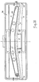
- - la figure 3 est une vue en plan de dessous de la lame à monter sous le suceur de la figure 1,
- - la figure 4 est une coupe transversale prise suivant la ligne IV-IV des figures 1 et 3,
- - les figures 5 à 9 sont des vues analogues à la figure 1 illustrant d'autres formes de réalisation du suceur en trait fin, ce suceur étant équipé d'une lame arrache-fils amovible représentée en trait épais,
- - la figure 10 est une vue analogue à la figure 1 faisant ressortir un perfectionnement apporté à la lame arrache-fils amovibles quels que soient la forme et l'emplacement de celle-ci,
- - la figure 11 est une coupe transversale prise suivant la ligne X-X de la figure 9,
- - la figure 12 est une vue analogue à la figure 11 concernant une sixième forme de réalisation d'un support amovible de tissu arrache-fils.
- - la figure 13 est une vue en plan de dessous montrant une septième forme de réalisation d'un suceur d'aspirateur, suceur qui est destiné à être équipé d'une lame arrache-fils escamotable, conforme à l'invention,
- - la figure 14 est une coupe brisée prise suivant la ligne XIV-XIV de la figure 13.
- - la figure 15 est une coupe prise suivant la ligne XV-XV de la figure 14.
- les figures 16 à 18 sont des vues analogues aux figures 13 à 15 respectivement illustrant une variante de réalisation.
- FIG. 1 is a bottom plan view showing a first embodiment of a vacuum cleaner nozzle, which is intended to be equipped with a removable wire puller blade, in accordance with the invention,
- FIG. 2 is a partial elevation, with cutaway taken along line II-II of FIG. 1, representing the nozzle equipped with the blade,
- FIG. 3 is a plan view from below of the blade to be mounted under the nozzle of FIG. 1,
- FIG. 4 is a cross section taken along the line IV-IV of FIGS. 1 and 3,
- FIGS. 5 to 9 are views similar to FIG. 1 illustrating other embodiments of the squeegee in thin lines, this squeegee being equipped with a removable wire stripper blade shown in thick line,
- FIG. 10 is a view similar to FIG. 1 showing an improvement made to the removable wire puller blade whatever the shape and the location thereof,
- FIG. 11 is a cross section taken on line XX of FIG. 9,
- - Figure 12 is a view similar to Figure 11 relating to a sixth embodiment of a removable support of thread-pulling fabric.
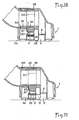
- FIG. 13 is a bottom plan view showing a seventh embodiment of a vacuum cleaner nozzle, which is intended to be fitted with a retractable wire puller blade, in accordance with the invention,
- - Figure 14 is a broken section taken along the line XIV-XIV of Figure 13.
- - Figure 15 is a section taken on the line XV-XV of Figure 14.
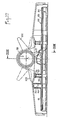
- Figures 16 to 18 are views similar to Figures 13 to 15 respectively illustrating an alternative embodiment.
Dans la première forme de réalisation décrite dans ce qui précède en se référant aux figures 1 à 4, une lame amovible 19 (figure 3) en matière plastique, en carton rigide ou autre est conformée en correspondance avec le canal arqué 9 pour s'y emboîter et est revêtue sur sa face apparente au moins, d'un tissu arrache-fils 20 dont les fibres orientées sont dirigées vers la fenêtre 11.In the first embodiment described in the foregoing with reference to Figures 1 to 4, a removable blade 19 (Figure 3) of plastic, rigid cardboard or other is shaped in correspondence with the
La lame 19 recouvre la fenêtre 14 et pour son maintien, indépendamment de celui exercé par l'aspiration à travers cette fenêtre, son emboîtement dans le canal 9 est réalisé sans jeu et même avec un léger serrage. Dans cette position d'emboîtement de la lame dans un canal, les fibres au repos du tissu 20 pointent sensiblement au même niveau que la surface de glissement de la semelle 4.The
Par ailleurs et ainsi que cela ressort des figures 2 à 4, une nervure 21 peut être formée en saillie sur la lame et clipsée dans la fenêtre 14.Furthermore, and as is apparent from FIGS. 2 to 4, a
Dans l'exemple représenté, la nervure 21 est conformée en U et s'emboîte dans un rebord rentrant 22 de la semelle 4 délimitant la fenêtre 14, le rebord coiffant le puits 3. Comme le montre la figure 4, la hauteur de la nervure 21 est déterminée afin que celle-ci ne s'oppose pas au pivotement de la tubulure 2.In the example shown, the
Bien entendu, le fait que la lame 19 soit arquée et revêtue sur une face seulement du tissu 20 conduit à ne prendre aucune précaution pour son positionnement, car il est certain que les fibres du tissu 20 seront toujours bien orientées.Of course, the fact that the
De plus, le démontage de la lame 19 est très facile puisqu'il suffit de glisser un outil mince, tel qu'un couteau, un tournevis... dans la fente 23 (figure 4) ménagée entre cette lame et le rebord 22 de la fenêtre 14 contigu à la plaquette arrache-fils 17 et de faire levier.In addition, the disassembly of the
La première forme de réalisation s'applique que le suceur comporte ou non une brosse 7 et que la tubulure 2 soit pivotante ou bien fixe. Il en est de même pour les autres formes de réalisation décrites dans ce qui suit.The first embodiment applies whether or not the nozzle has a
Dans la deuxième forme de réalisation décrite dans ce qui suit en se référant à la figure 5, une lame arrache-fils 29, dite rectiligne, dont la forme est symétrique par rapport à son axe longitudinal médian 27 perpendiculaire à la direction d'avancement, est logée dans le canal 25 et obture la partie verticale du passage 31 mais non la fenêtre 32. Pour maintenir la lame 29 dans ledit canal de façon démontable et la positionner correctement afin que les fibres de son tissu 20 soient dirigées vers la fenêtre 32, cette lame comporte deux "pions de détrompage" 33 situés dissymétriquement par rapport à l'axe médian d'avancement 28 du suceur et destinés à être engagés dans des trous de la semelle.In the second embodiment described in the following with reference to FIG. 5, a
Suivant la variante illustrée par la figure 6, la semelle 24 est semblable à la précédente à la différence près que la fenêtre 32 s'étend également en travers du canal 25. La semelle 24 coopère alors avec une lame arrache-fils 39 qui ressemble à la lame 29 selon la figure 5, à la seule différence près qu'elle comporte une partie médiane avancée 40 destinée à prendre place dans le passage 31 entre les éléments de bourrelet 30 et à obturer en partie la fenêtre 32.According to the variant illustrated in FIG. 6, the sole 24 is similar to the previous one except that the
Le maintien en place de cette lame 39 est obtenu comme dans la réalisation des figures 1 à 4, par une nervure 21 faisant saillie sur ladite lame et emboîtée au plus juste dans la fenêtre 32. Le positionnement se trouve automatiquement assuré. Des pions 41 peuvent cependant être prévus pour améliorer la fixation avec ou sans la nervure 21.The retention in place of this
Les éléments de bourrelet 30 peuvent être relativement courts, ce qui accroît la longueur du passage 31, et la fenêtre 32 peut déboucher en partie au moins dans le canal 25. Dans ce cas particulier, la lame amovible 29 reste efficace lorsqu'elle est montée et le suceur également lorsqu'elle est démontée.The
Suivant une troisième forme de réalisation illustrée par la figure 7, le suceur comporte une semelle 44 à trois canaux combinant ceux des semelles 4 et 24. Ainsi, on retrouve les canaux 8 et 9 de la semelle 4 séparés par le bourrelet continu 10, ainsi que la lame arquée 19 obturant la fenêtre 14 du canal 9 et fixée de façon amovible au moyen de la nervure 21 centrée dans ladite fenêtre. Le canal 8 ressemble à celui 25 du suceur 24 et communique avec le canal 26 par le passage 31 s'étendant entre les éléments de bourrelet 30. La fenêtre 11 de la semelle 4 est située dans le canal intermédiaire 8 de la semelle 44, mais s'étend jusque dans le passage 31 comme dans la semelle 24. Les effets avantageux d'aspiration et d'arrache-fils des deux suceurs perfectionnés selon les figures 1 à 4 et 5 se trouvent alors combinés.According to a third embodiment illustrated by FIG. 7, the nozzle comprises a sole 44 with three channels combining those of the
Suivant une quatrième forme de réalisation illustrée par la figure 8, la semelle 54 comporte, comme la semelle 44, trois canaux 55, 56 et 57, aux seules différences près que ces canaux sont rectilignes et que la lame 59 est logée dans le canal intermédiaire 56. Le canal marginal 55 comporte la fenêtre 14 et est séparé du canal intermédiaire 56 par le bourrelet continu 10. Le canal marginal 57 est séparé du canal intermédiaire 56 par les éléments de bourrelet 30 s'étendant de part et d'autre du passage 31, la fenêtre 32 étant ménagée dans ledit canal 56, le passage 31 et une partie de la largeur du canal 57.According to a fourth embodiment illustrated by FIG. 8, the sole 54 comprises, like the sole 44, three
Dans cette quatrième forme de réalisation, la lame 59 peut être revêtue d'une bande unique de tissu arrache-fils 20a ou 20b dont les fibres sont inclinées respectivement vers l'avant ou vers l'arrière pour arracher les fils ou les poils lorsque le suceur est poussé (flèche f1 ) ou tiré (flèche f2) ; la lame 59 est munie d'une nervure 21 de fixation et si l'utilisateur est attentif, elle peut être montée avec le tissu positionné selon 20a ou 20b par simple retournement avec la nervure en U ouverte vers l'avant ou vers l'arrière ; si le suceur est équipé de deux lames 59 avec bandes 20a et 20b respectivement, ces lames doivent être pourvues de "pions de détrompage" 33 ; cette disposition est particulièrement avantageuse pour l'utilisateur qui peut ainsi intervenir selon ses réflexes habituels,In this fourth embodiment, the
Suivant une cinquième forme de réalisation illustrée par la figure 9, la semelle 64 comporte trois canaux rectilignes 65, 66 et 67 dans lesquels débouchent des fenêtres d'aspiration 71, 72 et 73 respectivement et qui sont séparés par des bourrelets continus 74 et 75.According to a fifth embodiment illustrated in FIG. 9, the
Une lame arrache-fils 69 est montée dans le canal intermédiaire 66 d'une façon amovible au moyen de la nervure 21 centrée dans la fenêtre 72.A
Cette lame peut être revêtue, comme dans la quatrième forme de réalisation, de bandes 20a ou 20b et éventuellement munie de "pions de détrompage" 33 non représentés.This blade can be coated, as in the fourth embodiment, with
Avantageusement, elle est munie de deux bandes longitudinales 68 et 70 contiguës de tissu arrache-fils dont les fibres sont orientées symétriquement dans le sens des flèches f1 et f2, de façon que celles de la bande 68 soient dirigées vers la fenêtre 71 et celles de la bande 70 vers la fenêtre 73. Ainsi, la lame 59 peut-elle arracher les fils lorsque le suceur est déplacé en marche avant et en marche arrière respectivement. Les fils arrachés peuvent alors être avalés dans les deux sens par le suceur.Advantageously, it is provided with two contiguous
Bien entendu, cette lame 69 à bandes symétriques 68, 70 peut être plus étroite et montée, dans le canal intermédiaire 56 de la quatrième forme de réalisation selon la figure 8. Dans ce cas, les pions de détrompage 33 sont inutiles.Of course, this
Les lames 19, 29, 39 et 59 et 69 décrites dans ce qui précède peuvent être démontées au moyen d'un outil mince glissé dans la fente 23 (figure 4).The
Elles peuvent l'être également grâce à un prolongement 76 de la lame. Ce prolongement est représenté pour la lame 19 sur les figures 10 et 11. Il s'étend dans un décrochement 77 de la semelle 4 et fait saillie à l'arrière de celle-ci. Ainsi, en appuyant sur ledit prolongement 76 soit directement avec le pied 78 soit au moyen de la brosse périphérique 79 du suceur que la pédale manoeuvrée par le pied fait saillir autour de la semelle, on provoque le démontage de ladite lame.They can also be thanks to an
La lame emboîtable 19, 29, 39 ou 69 qui est destinée à supporter un tissu arrache-fils 20, à fermer l'un des canaux aspirants 9, 25, 56 ou 66 et à obturer en partie au moins la fenêtre correspondante 14, 32 ou 72, peut être remplacée, ainsi que cela ressort de la sixième forme de réalisation illustrée par la figure 12 par une coiffe 80 de préférence en matière plastique moulée. Celle-ci présente alors un rebord 81 susceptible d'être emboîté sur le boîtier de suceur 1 et d'y être fixé élastiquement au moyen de crochets 82. Dans cette position, le fond 83 de la coiffe est appliqué contre la semelle 4.The interlocking
Dans l'exemple illustré par la figure 12, la coiffe 80 est adaptée à la forme de réalisation selon les figures 1 à 4. Dans ce cas, le fond 83 comporte, d'une part, un renflement 84 destiné à se loger dans le canal 9 de la semelle et à obturer la fenêtre 14 et, d'autre part, une lumière 85 située en regard du canal 8. Le tissu 20 à fibres orientées est fixé dans une dépression extérieure du renflement 84. Par ailleurs, un bossage 86 fait saillie vers l'arrière pour permettre le démontage au pied de la coiffe 66.In the example illustrated in FIG. 12, the
Bien entendu, si la semelle comporte trois canaux, deux de ceux-ci peuvent être comblés par des tissus 20 rendus amovibles. A cet effet, les tissus peuvent être fixés sous la coiffe 80 ou bien sous des lames du type précité mais qui sont reliées entre elles par des traverses s'étendant au-dessus de la surface de glissement de la semelle 4 dans des passages reliant les canaux correspondants.Of course, if the sole has three channels, two of these can be filled with
La description qui précède en se référant aux figures 1 à 12, concerne des suceurs équipés de lames 19, 29, 39, 59 et 69 arrache-fils amovibles, susceptibles d'être démontées avec un outil ou le pied.The foregoing description with reference to FIGS. 1 to 12, relates to squeegees fitted with
Il peut être avantageux que la lame arrache-fils s'escamote dans le boîtier 1 par mouvement ascendant et constitue le fond du canal dans lequel elle est montée lorsque le suceur est utilisé pour enlever les poussières (position représentée en trait plein sur les figures 15 et 18), ladite lame obturant ledit canal et affleurant sensiblement la surface de glissement de la semelle 94 lorsque le suceur est utilisé pour arracher et avaler les fils (position représentée en trait mixte sur lesdites figures 15 et 18).It may be advantageous for the wire stripper blade to retract into the
Une telle lame escamotable 89 est illustrée par les figures 13 à 15 pour une septième forme de réalisation du suceur et par les figures 16 à 18 pour une variante de réalisation.Such a
Suivant la septième forme de réalisation, la semelle 94 du suceur délimite, comme celle de la première selon les figures 1 à 4, deux canaux 8 et 9 de même forme. Le canal antérieur 8 débouche sur les côtés par des passages extrèmes 12 et 13 et communique avec la tubulure d'aspiration par la fenêtre 11.According to the seventh embodiment, the sole 94 of the squeegee delimits, like that of the first according to Figures 1 to 4, two
Cependant, comme dans la deuxième forme de réalisation illustrée par la figure 5, les canaux 8 et 9 sont séparés l'un de l'autre par des éléments de bourrelet 30 entre lesquels est ménagé le passage central 31. Ce passage vertical établit une communication entre le canal antérieur 8 et le canal postérieur 9, lequel est exempt de fenêtre horizontale.However, as in the second embodiment illustrated in FIG. 5, the
Dans cette septième forme de réalisation, la paroi supérieure du canal postérieur 9 est constituée par la lame 89 en position haute illustrée en trait plein sur les figures 14, 15 et 17, 18. La dépression se propage à partir de la fenêtre 11 directement dans le canal antérieur 8 et, à travers le passage 31, dans le canal postérieur 9.In this seventh embodiment, the upper wall of the
Suivant la variante de réalisation illustrée par les figures 16 à 18, les canaux 8 et 9 sont séparés l'un de l'autre par un bourrelet continu 10. Ainsi que cela ressort clairement de la figure 18, des passages verticaux sont constitués par des lumières 87 découpées par les parois du bourrelet 10 au-dessus de l'arête 88 de celui-ci ; cette arête n'est donc pas interrompue sur toute la longueur du suceur et remplit dès lors complètement son rôle de "massage" des toupets du tapis ; malgré cela, les passages 87 établissent une communication du canal antérieur 8 et de sa fenêtre 11 avec le canal postérieur 9 lorsque la lame 89 est relevée en position haute.According to the variant embodiment illustrated in FIGS. 16 to 18, the
Qu'il s'agisse de la réalisation selon les figures 13 à 15 ou de la réalisation selon les figures 16 à 18, la lame 89 coopère avec un mécanisme d'actionnement intégré dans le suceur et permettant de déplacer cette lame entre les deux positions précitées en la maintenant positivement au moins dans la position basse d'arrache-fils.Whether it is the embodiment according to FIGS. 13 to 15 or the embodiment according to FIGS. 16 to 18, the
Dans l'exemple représenté, la lame 89 fait corps avec deux colonnettes verticales 90 traversant le fond 91 du canal 9 de la semelle 94, ces colonnettes étant guidées en translation au-dessus dans des fourreaux 92 venus de moulage avec le boîtier. La lame peut donc se déplacer parallèlement à elle-même.In the example shown, the
Le mécanisme d'actionnement comporte, pour le rappel élastique de ladite lame vers la position haute d'escamotage représentée en trait plein, deux ressorts 93. Cette lame fait corps avec deux tiges creuses 95 traversant le fond 91 du canal 9 et faisant saillie au-dessus. Chaque ressort 93 est enfilé sur la partie saillante de la tige correspondante et est interposé entre ce fond 91 et une collerette 96 rapportée sur l'extrémité libre de la tige considérée.The actuating mechanism comprises, for the elastic return of said blade to the high retraction position shown in solid lines, two springs 93. This blade is integral with two
Le mécanisme d'actionnement comporte, pour l'actionnement positif de ladite lame 89 vers la position basse d'arrache-fils représentée en trait mixte, un doigt 97 faisant corps avec un manchon 98 monté tournant autour d'un axe géométrique du boîtier 1 s'étendant orthogonalement à la direction longitudinale de ladite lame.The actuation mechanism comprises, for the positive actuation of said
Dans cet exemple tel qu'il est représenté sur les figures 15 et 18, la tubulure d'aspiration 2 est étagée et montée tournante dans une partie tubulaire 99 également étagée du boîtier 1 de façon à ménager entre elles un espace libre dans lequel le manchon 98 est lui-même monté tournant. La partie 99 de la tubulure d'aspiration est immobilisée en translation par un anneau élastique 100 et le manchon 98 par le doigt 97 traversant une lumière 101 de ladite partie. Pour la manoeuvre, ledit manchon 98 fait corps avec des pédales 102 et 103 situées sur les côtés. Lorsque la pédale 103 est enfoncée et que la pédale 102 fait saillie (position représentée en trait plein sur la figure 14 ou 17), le doigt 97 ne sollicite pas la lame 89 et celle-ci occupe la position haute d'escamotage. Par contre, lorsque la pédale 102 est enfoncée et que la pédale 103 fait saillie (position représentée en trait mixte sur la figure 14 ou 17), le doigt 97 ayant sollicité la lame 89 pour la faire descendre, maintient cette lame en position basse d'arrache-fils.In this example as shown in Figures 15 and 18, the
Il peut être avantageux d'amplifier la course de descente de la lame 89 pour une amplitude angulaire de pivotement normale du manchon de commande 98. A cet effet, la lame 89 fait corps avec une came ascendante 104 destinée à coopérer avec le doigt d'actionnement 97 lors de son pivotement.It may be advantageous to amplify the downward travel of the
Bien entendu, le mécanisme d'actionnement peut coopérer avec deux lames arrache-fils ou davantage. En outre, l'escamotage peut être appliqué aux formes de réalisation dans lesquelles la lame est amovible.Of course, the actuation mechanism can cooperate with two or more wire stripping blades. In addition, the retraction can be applied to embodiments in which the blade is removable.
Claims (19)
Priority Applications (1)
| Application Number | Priority Date | Filing Date | Title |
|---|---|---|---|
| AT87401071T ATE55232T1 (en) | 1986-05-30 | 1987-05-13 | VACUUM CLEANER NOSE WITH THREAD COLLECTING BRISTLES. |
Applications Claiming Priority (2)
| Application Number | Priority Date | Filing Date | Title |
|---|---|---|---|
| FR8607812A FR2599236B1 (en) | 1986-05-30 | 1986-05-30 | VACUUM CLEANER WITH WIRE PULLER. |
| FR8607812 | 1986-05-30 |
Publications (2)
| Publication Number | Publication Date |
|---|---|
| EP0248695A1 EP0248695A1 (en) | 1987-12-09 |
| EP0248695B1 true EP0248695B1 (en) | 1990-08-08 |
Family
ID=9335840
Family Applications (1)
| Application Number | Title | Priority Date | Filing Date |
|---|---|---|---|
| EP87401071A Expired - Lifetime EP0248695B1 (en) | 1986-05-30 | 1987-05-13 | Vacuum cleaner nozzle with thread catching bristles |
Country Status (6)
| Country | Link |
|---|---|
| US (1) | US4888852A (en) |
| EP (1) | EP0248695B1 (en) |
| AT (1) | ATE55232T1 (en) |
| CA (1) | CA1282916C (en) |
| DE (1) | DE3764191D1 (en) |
| FR (1) | FR2599236B1 (en) |
Families Citing this family (34)
| Publication number | Priority date | Publication date | Assignee | Title |
|---|---|---|---|---|
| FR2642637B1 (en) * | 1989-02-09 | 1994-10-07 | Olivier Ets Georges | VACUUM CLEANER FOR CARPETS OR CARPETS, HARD DRY FLOORS AND HARD WET FLOORS |
| FR2653654B1 (en) * | 1989-10-31 | 1992-02-14 | Olivier Ets Georges | ROTATING CONNECTION HOUSING FOR VACUUM CLEANER. |
| FR2678818B1 (en) * | 1991-07-11 | 1995-07-13 | Olivier Ets Georges | WIRE-TAPPING DEVICE FOR VACUUM CLEANER SOLE. |
| DE4201596C2 (en) * | 1992-01-22 | 2001-07-05 | Gerhard Kurz | Floor nozzle for vacuum cleaners |
| DE4304681C2 (en) * | 1993-02-16 | 1996-06-05 | Wessel Werk Gmbh | One-piece vacuum cleaner nozzle |
| DE4304682C2 (en) * | 1993-02-16 | 1996-01-25 | Wessel Werk Gmbh | Vacuum cleaner nozzle |
| DE4406156A1 (en) * | 1994-02-25 | 1995-08-31 | Licentia Gmbh | Suction mouthpiece for vacuum cleaners |
| US5557823A (en) * | 1995-05-26 | 1996-09-24 | Jma & Associates | Vacuum cleaner attachment |
| DE19602723C2 (en) * | 1996-01-26 | 2001-04-19 | Gerhard Kurz | Device for operating a vacuum cleaner |
| GB0023732D0 (en) * | 2000-09-28 | 2000-11-08 | Notetry Ltd | A floor tool |
| US6588058B2 (en) * | 2001-03-20 | 2003-07-08 | Roger P. Vanderlinden | Large area surface cleaning tool |
| US6584640B2 (en) * | 2001-03-20 | 2003-07-01 | Roger P. Vanderlinden | Large area surface cleaning tool for suctioning both dust and debris |
| DE10241492B4 (en) * | 2002-09-07 | 2006-11-02 | Wessel-Werk Gmbh | Floor nozzle for vacuum cleaner |
| DE10241491B4 (en) * | 2002-09-07 | 2006-10-26 | Wessel-Werk Gmbh | Floor nozzle for vacuum cleaner |
| KR100613102B1 (en) * | 2004-07-01 | 2006-08-17 | 삼성광주전자 주식회사 | A suction port assembly and a vacuum cleaner having the same |
| DE202005020507U1 (en) * | 2005-12-20 | 2006-04-13 | Alfred Kärcher Gmbh & Co. Kg | Floor nozzle for vacuum cleaner |
| DE102006060855B4 (en) * | 2006-12-22 | 2013-08-01 | Wessel-Werk Gmbh | Floor nozzle for vacuum cleaner |
| KR20090017870A (en) * | 2007-08-16 | 2009-02-19 | 삼성광주전자 주식회사 | Suction brush for vacuum cleaner having hair removal unit |
| CN106079159A (en) | 2008-06-26 | 2016-11-09 | 谐和能源有限责任公司 | The System and method for of garbage storage integration |
| GB2468514B (en) * | 2009-03-12 | 2012-07-11 | Dyson Technology Ltd | A surface-treating head |
| AU2010201002B2 (en) * | 2009-03-20 | 2014-06-26 | Bissell Inc. | Vacuum accessory tool |
| AU2010261574C1 (en) * | 2009-06-17 | 2014-04-03 | Dyson Technology Limited | A tool for a surface treating appliance |
| EP2453780B1 (en) * | 2009-07-16 | 2013-11-13 | Dyson Technology Limited | A surface treating head |
| GB0912356D0 (en) * | 2009-07-16 | 2009-08-26 | Dyson Technology Ltd | A surface treating head |
| GB2479530B (en) * | 2010-04-12 | 2012-07-18 | Ponnampalam Shanmugaratnam | Vacuum cleaner hair removal pads |
| CN103717715B (en) | 2011-06-03 | 2017-09-15 | 谐和能源有限责任公司 | The system and method that fuel feedstocks are designed by waste materials preparation process |
| GB2496663B (en) * | 2011-11-18 | 2014-07-30 | Dyson Technology Ltd | A cleaner head |
| US9126204B1 (en) | 2013-01-24 | 2015-09-08 | Wm Intellectual Property Holdings L.L.C. | Process and system for producing engineered fuel |
| CN104013355A (en) * | 2014-05-09 | 2014-09-03 | 苏州艾利欧电器有限公司 | Multi-air-channel floor brush |
| CN104013356A (en) * | 2014-05-09 | 2014-09-03 | 苏州艾利欧电器有限公司 | Floor brush with independent air flues |
| CA2960305A1 (en) | 2015-06-24 | 2016-12-29 | Wm Intellectual Property Holdings, L.L.C. | Process for producing engineered fuel |
| DE102015113460A1 (en) * | 2015-08-14 | 2017-02-16 | Vorwerk & Co. Interholding Gmbh | Floor nozzle for a cleaning device, in particular for a vacuum cleaner |
| CN107126151A (en) * | 2017-07-12 | 2017-09-05 | 小狗电器互联网科技(北京)股份有限公司 | Floor brush of dust collector and dust catcher |
| US11607101B2 (en) | 2019-08-05 | 2023-03-21 | Bissell Inc. | Vacuum cleaner accessory tool |
Family Cites Families (12)
| Publication number | Priority date | Publication date | Assignee | Title |
|---|---|---|---|---|
| US2703903A (en) * | 1949-12-22 | 1955-03-15 | Electrolux Ab | Combination suction cleaner nozzle and brush member |
| FR1085915A (en) * | 1953-03-24 | 1955-02-08 | Cleaning utensil | |
| US2893048A (en) * | 1955-04-21 | 1959-07-07 | Health Mor Inc | Suction cleaner nozzle construction for cleaning cotton rugs |
| DE1072957B (en) * | 1958-07-04 | 1960-01-14 | WiIdbergerhütte Hans Wessel (Bez. Köln) | Brush consisting of a bristle carrier plate and one or more bristle rails |
| DE2024616B2 (en) * | 1970-05-20 | 1971-08-05 | Schwab geb Gitschel, Hilde, Zem bold, Heinz, 4000 Dusseldorf | DEVICE FOR CLEANING TEXTILES |
| DE2100465A1 (en) * | 1971-01-07 | 1972-07-20 | Schwab Geb Gitschel H | Thread take-up for a device for cleaning textiles |
| GB1340466A (en) * | 1971-05-12 | 1973-12-12 | Allstar Verbrauchsgueter Gmbh | Nozzle for vacuum cleaner |
| DE2220815A1 (en) * | 1972-04-27 | 1973-11-08 | Hans Wessel | VACUUM CLEANER FOR CARPET AND FLOOR CLEANING |
| US3820189A (en) * | 1972-12-11 | 1974-06-28 | E Roth | Brush adaptor for vacuuming |
| DE7237505U (en) * | 1973-11-14 | 1974-03-21 | Wessel H | Vacuum cleaner nozzle with thread take-up |
| US4319379A (en) * | 1980-04-29 | 1982-03-16 | Carrigan William J | Pickup |
| DE3025977C2 (en) * | 1980-07-09 | 1985-06-13 | Allstar Verbrauchsgüter GmbH & Co KG, 6000 Frankfurt | Mouthpiece for vacuum cleaner nozzles |
-
1986
- 1986-05-30 FR FR8607812A patent/FR2599236B1/en not_active Expired
-
1987
- 1987-05-13 DE DE8787401071T patent/DE3764191D1/en not_active Expired - Fee Related
- 1987-05-13 AT AT87401071T patent/ATE55232T1/en not_active IP Right Cessation
- 1987-05-13 EP EP87401071A patent/EP0248695B1/en not_active Expired - Lifetime
- 1987-05-27 US US07/054,589 patent/US4888852A/en not_active Expired - Fee Related
- 1987-05-28 CA CA000538275A patent/CA1282916C/en not_active Expired - Lifetime
Also Published As
| Publication number | Publication date |
|---|---|
| FR2599236B1 (en) | 1989-03-10 |
| EP0248695A1 (en) | 1987-12-09 |
| DE3764191D1 (en) | 1990-09-13 |
| FR2599236A1 (en) | 1987-12-04 |
| CA1282916C (en) | 1991-04-16 |
| ATE55232T1 (en) | 1990-08-15 |
| US4888852A (en) | 1989-12-26 |
Similar Documents
| Publication | Publication Date | Title |
|---|---|---|
| EP0248695B1 (en) | Vacuum cleaner nozzle with thread catching bristles | |
| JPH05261041A (en) | Floor nozzle for vacuum cleaner | |
| FR2913325A1 (en) | ASPIRATOR AND METHOD FOR REMOVING HAIR FROM SURFACE WHICH IS CHARGED | |
| EP0382598B1 (en) | Suction nozzle for carpets or for hard dry and damp floors | |
| EP1173085B1 (en) | Vacuum cleaner nozzle with scraper blade | |
| EP1381301A1 (en) | Endpiece for a vacuum cleaner | |
| US20100236019A1 (en) | Nozzle for a floor cleaning device | |
| WO2013045818A1 (en) | Vacuum cleaner head | |
| EP1045660B1 (en) | Vacuum cleaner dusting brush | |
| EP0734213B1 (en) | Brush containing comb | |
| US8418313B1 (en) | Power cord protection system for a floor cleaner | |
| FR2729842A1 (en) | VACUUM SUCKER | |
| EP1488726B1 (en) | Suction nozzle for vacuum cleaner | |
| EP1488728B1 (en) | Suction nozzle for a vacuum cleaner | |
| KR101253245B1 (en) | steam cleaner | |
| EP3834691A1 (en) | Cleaning head provided with a removable cleaning element | |
| CA3115133A1 (en) | Electric floor sweeper | |
| EP0522968B1 (en) | Thread eliminating device | |
| WO2016206734A1 (en) | Vacuum cleaner nozzle and vacuum cleaner comprising a vacuum cleaner nozzle | |
| EP1488727B1 (en) | Suction nozzle of a vacuum cleaner | |
| EP1369074A1 (en) | Suction nozzle with scraping device | |
| KR101354675B1 (en) | Suction device of vacuum cleaner | |
| FR2665071A1 (en) | Broom/brush with floor cloth having integral (wringing) drying | |
| JPH06343586A (en) | Suction implement for vacuum cleaner | |
| JPH05253123A (en) | Suction implement for vacuum cleaner |
Legal Events
| Date | Code | Title | Description |
|---|---|---|---|
| PUAI | Public reference made under article 153(3) epc to a published international application that has entered the european phase |
Free format text: ORIGINAL CODE: 0009012 |
|
| AK | Designated contracting states |
Kind code of ref document: A1 Designated state(s): AT BE CH DE ES FR GB IT LI NL SE |
|
| 17P | Request for examination filed |
Effective date: 19880505 |
|
| 17Q | First examination report despatched |
Effective date: 19890817 |
|
| GRAA | (expected) grant |
Free format text: ORIGINAL CODE: 0009210 |
|
| AK | Designated contracting states |
Kind code of ref document: B1 Designated state(s): AT BE CH DE ES FR GB IT LI NL SE |
|
| PG25 | Lapsed in a contracting state [announced via postgrant information from national office to epo] |
Ref country code: IT Free format text: LAPSE BECAUSE OF FAILURE TO SUBMIT A TRANSLATION OF THE DESCRIPTION OR TO PAY THE FEE WITHIN THE PRESCRIBED TIME-LIMIT;WARNING: LAPSES OF ITALIAN PATENTS WITH EFFECTIVE DATE BEFORE 2007 MAY HAVE OCCURRED AT ANY TIME BEFORE 2007. THE CORRECT EFFECTIVE DATE MAY BE DIFFERENT FROM THE ONE RECORDED. Effective date: 19900808 Ref country code: NL Effective date: 19900808 Ref country code: SE Free format text: THE PATENT HAS BEEN ANNULLED BY A DECISION OF A NATIONAL AUTHORITY Effective date: 19900808 Ref country code: AT Effective date: 19900808 |
|
| REF | Corresponds to: |
Ref document number: 55232 Country of ref document: AT Date of ref document: 19900815 Kind code of ref document: T |
|
| REF | Corresponds to: |
Ref document number: 3764191 Country of ref document: DE Date of ref document: 19900913 |
|
| GBT | Gb: translation of ep patent filed (gb section 77(6)(a)/1977) | ||
| PG25 | Lapsed in a contracting state [announced via postgrant information from national office to epo] |
Ref country code: ES Free format text: LAPSE BECAUSE OF FAILURE TO SUBMIT A TRANSLATION OF THE DESCRIPTION OR TO PAY THE FEE WITHIN THE PRESCRIBED TIME-LIMIT Effective date: 19901119 |
|
| NLV1 | Nl: lapsed or annulled due to failure to fulfill the requirements of art. 29p and 29m of the patents act | ||
| PG25 | Lapsed in a contracting state [announced via postgrant information from national office to epo] |
Ref country code: BE Effective date: 19910531 |
|
| PLBE | No opposition filed within time limit |
Free format text: ORIGINAL CODE: 0009261 |
|
| STAA | Information on the status of an ep patent application or granted ep patent |
Free format text: STATUS: NO OPPOSITION FILED WITHIN TIME LIMIT |
|
| 26N | No opposition filed | ||
| BERE | Be: lapsed |
Owner name: ETS GEORGES OLIVIER Effective date: 19910531 |
|
| PGFP | Annual fee paid to national office [announced via postgrant information from national office to epo] |
Ref country code: GB Payment date: 19940506 Year of fee payment: 8 |
|
| PGFP | Annual fee paid to national office [announced via postgrant information from national office to epo] |
Ref country code: CH Payment date: 19940516 Year of fee payment: 8 |
|
| PGFP | Annual fee paid to national office [announced via postgrant information from national office to epo] |
Ref country code: DE Payment date: 19940526 Year of fee payment: 8 |
|
| PGFP | Annual fee paid to national office [announced via postgrant information from national office to epo] |
Ref country code: FR Payment date: 19940531 Year of fee payment: 8 |
|
| PG25 | Lapsed in a contracting state [announced via postgrant information from national office to epo] |
Ref country code: GB Effective date: 19950513 |
|
| PG25 | Lapsed in a contracting state [announced via postgrant information from national office to epo] |
Ref country code: LI Effective date: 19950531 Ref country code: CH Effective date: 19950531 |
|
| GBPC | Gb: european patent ceased through non-payment of renewal fee |
Effective date: 19950513 |
|
| REG | Reference to a national code |
Ref country code: CH Ref legal event code: PL |
|
| PG25 | Lapsed in a contracting state [announced via postgrant information from national office to epo] |
Ref country code: DE Effective date: 19960201 |
|
| PG25 | Lapsed in a contracting state [announced via postgrant information from national office to epo] |
Ref country code: FR Effective date: 19960229 |
|
| REG | Reference to a national code |
Ref country code: FR Ref legal event code: ST |
|
| REG | Reference to a national code |
Ref country code: FR Ref legal event code: ST |