EP0248313B1 - Bakenständer - Google Patents
Bakenständer Download PDFInfo
- Publication number
- EP0248313B1 EP0248313B1 EP87107584A EP87107584A EP0248313B1 EP 0248313 B1 EP0248313 B1 EP 0248313B1 EP 87107584 A EP87107584 A EP 87107584A EP 87107584 A EP87107584 A EP 87107584A EP 0248313 B1 EP0248313 B1 EP 0248313B1
- Authority
- EP
- European Patent Office
- Prior art keywords
- post
- adapter
- base plate
- recess
- beacon
- Prior art date
- Legal status (The legal status is an assumption and is not a legal conclusion. Google has not performed a legal analysis and makes no representation as to the accuracy of the status listed.)
- Expired - Lifetime
Links
Images


Classifications
-
- E—FIXED CONSTRUCTIONS
- E01—CONSTRUCTION OF ROADS, RAILWAYS, OR BRIDGES
- E01F—ADDITIONAL WORK, SUCH AS EQUIPPING ROADS OR THE CONSTRUCTION OF PLATFORMS, HELICOPTER LANDING STAGES, SIGNS, SNOW FENCES, OR THE LIKE
- E01F9/00—Arrangement of road signs or traffic signals; Arrangements for enforcing caution
- E01F9/60—Upright bodies, e.g. marker posts or bollards; Supports for road signs
- E01F9/623—Upright bodies, e.g. marker posts or bollards; Supports for road signs characterised by form or by structural features, e.g. for enabling displacement or deflection
- E01F9/631—Upright bodies, e.g. marker posts or bollards; Supports for road signs characterised by form or by structural features, e.g. for enabling displacement or deflection specially adapted for breaking, disengaging, collapsing or permanently deforming when deflected or displaced, e.g. by vehicle impact
- E01F9/638—Upright bodies, e.g. marker posts or bollards; Supports for road signs characterised by form or by structural features, e.g. for enabling displacement or deflection specially adapted for breaking, disengaging, collapsing or permanently deforming when deflected or displaced, e.g. by vehicle impact by connection of stud-and-socket type, e.g. spring-loaded
-
- E—FIXED CONSTRUCTIONS
- E01—CONSTRUCTION OF ROADS, RAILWAYS, OR BRIDGES
- E01F—ADDITIONAL WORK, SUCH AS EQUIPPING ROADS OR THE CONSTRUCTION OF PLATFORMS, HELICOPTER LANDING STAGES, SIGNS, SNOW FENCES, OR THE LIKE
- E01F9/00—Arrangement of road signs or traffic signals; Arrangements for enforcing caution
- E01F9/60—Upright bodies, e.g. marker posts or bollards; Supports for road signs
- E01F9/688—Free-standing bodies
- E01F9/692—Portable base members therefor
-
- Y—GENERAL TAGGING OF NEW TECHNOLOGICAL DEVELOPMENTS; GENERAL TAGGING OF CROSS-SECTIONAL TECHNOLOGIES SPANNING OVER SEVERAL SECTIONS OF THE IPC; TECHNICAL SUBJECTS COVERED BY FORMER USPC CROSS-REFERENCE ART COLLECTIONS [XRACs] AND DIGESTS
- Y10—TECHNICAL SUBJECTS COVERED BY FORMER USPC
- Y10T—TECHNICAL SUBJECTS COVERED BY FORMER US CLASSIFICATION
- Y10T403/00—Joints and connections
- Y10T403/70—Interfitted members
- Y10T403/7098—Non-circular rod section is joint component
Definitions
- beacons On streets and squares, various types of beacons as well as information signs, prohibition signs, barriers and the like must be temporarily set up again and again.
- beacons with or without additional traffic signs or lamps are placed in large numbers in close succession in order to create a route that is as visually complete as possible on the route sections deviating from the usual traffic route.
- These beacons are usually attached to beacon stands, which are also called footplate stands and which have a footplate, a beacon tube and a holder between the beacon tube and the footplate.
- the part of the holder on the base plate generally consists of a pocket with a square cross section.
- the footplate In the case of a metal version of the footplate, it is formed by its structural parts and / or by additionally welded-on steel bar sections.
- the pocket In the case of plastic footplates and the like, the pocket is formed as a recess in the top of the footplate.
- the mostly round beacon tube has a square foot that fits the bag at its lower end. In part, it is formed by welded bar sections.
- the square foot is formed by a plastic molded part with a cuboid shape, which has a round through tube into which the beacon tube is inserted and is usually secured against rotation by a rivet.
- the beacon tubes are generally designed as galvanized steel tubes which, due to their diameter and wall thickness, have a considerable moment of resistance to bending to have. If such a beacon stand is driven around by a vehicle, the beacon tube is bent and usually even kinked. Sometimes the beacon tube is torn out of the footplate and flung away. In the cases in which the beacon tube jams in the holder, the beacon tube exerts a leverage effect on the footplate due to its high resistance moment, so that it is raised on the drive-up side. It can drill into the underside of the vehicle traveling over it and cause serious damage to the front axle, especially to the parts of the steering and braking system. In addition, the vehicle can be deflected from its direction of travel, so that it comes off the road or drives into it in oncoming traffic.
- the invention specified in claim 1 or 2 is based on the object of designing beacon stands in such a way that, in particular, the risk of the footplate rising up is reduced or eliminated when the beacon stand is passed over.
- this post Due to the fact that a post with an M-profile is used instead of a beacon tube, this post has a sufficiently high resistance to bending for the vehicles passing by, e.g. due to gusts of wind or air blows, so that the beacon sheet or the beacon body attached to the post or else a traffic sign maintains its position in the correct orientation. If such a beacon stand is run over and there is a higher lateral load on the post, the post is bent just above the footplate. At the bending point, the webs of the M-profile, which run partly parallel and partly at an angle to one another, are brought together. In a way, they are folded up.
- the embodiment of the beacon stand according to claim 1 is particularly suitable for converting existing beacon stands, in which the previously existing foot plates can continue to be used until one day it becomes necessary to replace them with a new foot plate, which is then another Embodiment can have.
- the embodiment of the beacon stand according to claim 2 is particularly suitable for those beacon stands, in which the base plate is therefore completely matched to the profile of the post with the M-profile.
- the adapter ensures that the parts of the adapter protruding into the spaces between the individual webs of the M-profile of the post provide additional support. This also ensures that with a higher lateral load on the post and at the beginning of a bending process in the longitudinal section of the post received by the adapter, its webs are held in the predetermined mutual assignment and the resulting mutual distance, so that the post does not move in the The footplate is recessed and the seat of the post is loosened, but that the post is held in the adapter and thus in the recess of the footplate and the bending or bending process outside the holder takes place or the bending process itself is not disturbed by foreign parts.
- the same is achieved for posts in foot plates with a downward recess.
- the adapter at the foot of the post in the direction of the bulge has a dimension which is greater than the clear width of the recess in the footplate. Because the adapter part with the bulge is provided on the inside with an axial recess which is open on the end face, the wall part with the bulge has an increased bending elasticity. When a post is inserted with such an adapter, the wall part with the ramp-shaped recess is increasingly elastically deformed inwards. The elastic restoring force of this wall part is then constantly maintained, so that this adapter exerts a considerable clamping force between the post and the footplate.
- such a post has a very firm fit in the footplate, which makes additional fastening parts unnecessary, which not only makes the beacon stand cheaper, but can also be assembled and disassembled more quickly.
- a reliable permanent connection of the adapter to the post is possible, for which no further fastening means are also required.
- the bending moment against bending is significantly increased in this length section.
- the stiffening elements are attached in a height range in which the beacon stand is usually from If the bumper of a passenger car is hit, the stiffening elements ensure that there is no second kink at the point of impact of the bumper under its impact, at which the parts of the post, the beacon blade or the beacon body or a traffic sign or other signs are located above the force application point traffic engineering parts under the effect of their inertia relative to the forward bending movement do not remain relatively behind and thereby strike back against the moving vehicle and damage the vehicle.
- Such a design of the beacon stand is particularly advantageous when higher acceleration speeds and the resulting higher acceleration and, as a result, higher inertia forces are to be expected.
- the reinforcing elements can be relatively easily attached to the post, a permanent connection between the stiffening elements and the post being guaranteed even if the post is elastically deformed or undergoes plastic deformation within certain limits.
- both the deformation resistance of the post against denting and the moment of resistance of the post against bending is greatly increased, but without the mass of the post in this area increasing very much.
- the connecting rigidity of the post is increased by an embodiment of the beacon stand according to claim 11.
- the risk of injury when handling the post is reduced, and at the same time the pressing of the post into the recess of a base plate is facilitated, in particular if the adapter is designed according to claim 5 and has a ramp-shaped bulge.
- the design of the post according to claim 11 of the shape is made that the stiffening elements and their end plate is formed like the adapter in the embodiment according to claim 5, one and the same plastic molding can be used for both ends of the post. This significantly reduces the cost of manufacturing and storing these parts.
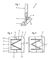
- the beacon stand 10 shown as a whole in FIG. 1 has a base plate 11, a beacon body 12 and a post 13.
- the foot plate 11 has a rectangular plan. In rough approximation it has a shape like a hipped roof with the ridge area flattened. However, it could also have any other body shape, for example that of a flat elongated cuboid.
- a recess 15 In the flat upper side 14 of the base plate 11 there is a recess 15, generally in the middle, which usually has a square outline. In some beacon stands of this type, the recess 15 is designed as a through hole, but in others as a blind hole. This recess 15 forms part of the holder for the post 13.
- the beacon body 12 is designed as a hollow body which has a lenticular or a rectangular outline at the lower end.
- the beacon body 12 has a rectangular cross-sectional shape at the upper closed end, which is generally narrower than the plan at the lower end.
- the side surfaces of the beacon body run in a continuous transition to the upper cross-sectional shape.
- the two flat side surfaces are slightly inclined towards each other.
- the beacon body 12 has a through hole in the middle of its plan area, which is matched to the shape and dimensions of the post 13. Additional guide and / or holding elements for the post 13 are present at least in the region of this through hole and / or also in the interior of the hollow body 12. Often there is also a transverse through hole in the beacon body 12 and present in the post 13, into which a holding or securing pin is inserted, through which the two parts are held together.
- the post 13 is made of metal, generally as a light metal extrusion. It has an M-profile as can be seen in FIG. 2.
- the two side webs 16 of the M-profile are aligned parallel to one another. They have the same length among themselves, which is at least approximately the same as their mutual outer distance.
- the length of the side webs 16 and their outer spacing depend on the shape and the clear width of the recess 15 in the base plate 11. If the recess 15 has a square rather than a square outline, care must be taken that the M profile of the Post 13, the side webs 16 is matched to the length of those side walls that are aligned transversely to the longitudinal extent of the foot plate 11.
- the two center webs 17 of the M-profile are arranged in a V-shape and are designed such that they extend from the connection point 18 with the respectively adjacent side web at least approximately to the middle of the connecting section of the free ends 20 of the two side webs 16. Under these conditions, it is achieved that at least the V-shaped portion of the M-profile formed by the two central webs always remains in the middle of the recess 15 because the triangle spanned by them is at their union point 19 and at the connection points 18 or at least the adjoining part of the two side webs 16 is supported on the side walls of the recess 15.
- the M-profile of the post 13 is shown with sharp edges in FIG. 2.
- the profile shape can be somewhat flattened on the outside and somewhat rounded on the inside.
- the Post 13 is not made as a light metal extruded profile but as a folded profile from sheet metal, there are roundings of the M-profile at the transition points from one side web to the subsequent center web or between the two metal webs, but these should be kept as low as possible.
- the foot plate 21 has a recess 22 which in turn has an M-shaped outline shape as a negative shape to the M-profile of the post 13.
- This plan shape is matched to the post 13 so that the end portion of the post 13 can be inserted into the recess 16 and has a tight fit in it.
- This close coordination applies in particular to those areas of the recess 22 which accommodate the side webs 16 and middle webs 17 of the post 13.
- the recess 16 can be made with larger roundings of their outline shape in order to facilitate the insertion of a post 13.
- the very close approximation of the outline shape of the recess 16 to the M-profile of the post 13 results in a very good hold of all the profile parts of the post 13.
- a similar close guidance of the profile parts of the post 13 and the resulting good hold of the post 13 in the base plate can be achieved by inserting an adapter 23 into the recess 15, the outer shape of which and dimensions are closely matched to the shape and dimensions of the recess 15.
- This adapter 23 has a lateral recess 24 on each of two sides facing away from one another and a central recess 25 in the central region thereof They are aligned perpendicularly and merge into one another and, at least approximately, represent a negative form of the M-profile of the post 13.
- larger roundings and thus corresponding deviations of the boundary walls of the recesses 24 and 25 from the nominal geometric shape of the M-profile are possible on the inside of the transition points between two profile parts.
- the two adapter parts 26 and 27 are mirror images of one another.
- the adapter part 28 has approximately a shape which arises from an adapter parts 26 and 27 which are joined together on their back surfaces.
- the three adapter parts 26 ... 28 are made in one piece with a base plate 29 (FIG. 5).
- This base plate 29 has a plan area which is closely matched to the plan of the recess 15 of the base plate 11 and which therefore ensures that the adapter 23 fits well in the recess 15.
- a securing of the adapter 23 can be created by providing a through hole 32 in the floor area of the adapter part 28 in the bottom part 31 of the foot plate 11 which closes off the recess 15 at the bottom, that a threaded hole 33 in the form of a blind hole is present in the line of alignment in the adapter 23 and that a fastening screw 34 is inserted through the through hole 32 and screwed into the threaded hole 33.
- a modified adapter 35 shown in FIG. 6 is used. Its floor plan is the same as the adapter 23 (Fig. 4) or at least equal to the floor plan of the passage.
- the base plate 36 which unites the adapter parts to one another, is provided with a circumferential collar 37, which is already indicated in FIG. This collar 37 protrudes all around beyond the outline of the recess 15 ⁇ . At least two diametrically located points, there are fastening means approximately in the form of fastening screws 38, which are indicated in FIG.
- the base plate 11 or 11 ⁇ is provided on its underside with feet 39 or 39 ⁇ , through which there is sufficient clearance for the head on the underside of the base plate the fastening screw 34 or for the collar 37 on the base plate 36 remains free. If there is no such free space, the fastening screw 34 would have to be designed as a countersunk screw or a recess should be provided on the underside of the foot plate 11 for this purpose. In a similar manner, a corresponding recess would have to be provided on the underside of the base plate 11 ⁇ for the collar 38.
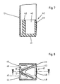
- the adapter 40 for the post 13, which can be seen in FIGS. 7 and 8, is modified in some features compared to the adapter 23 (FIGS. 4 and 5).
- the continuous base plate 41 With the continuous base plate 41, the outline of which is at least approximately the same as the outline of the recess 15 of the base plate 11, the three column-like or peg-like adapter parts 42 ... 44 are formed, between which the post 13 with the M-profile can be inserted.
- the middle adapter part 42 with the outline shape of an isosceles triangle is provided on the inside with an axial recess 45 which extends from the base plate 41 to the free end face of the adapter 40 and which opens out there.
- the adapter parts 43 and 44 are each provided with a recess 46 and 47, respectively.
- the recess 45 gives the outer wall 48 of the adapter part 42 a certain elasticity in the direction of the interior of the recess 45.
- a bulge 49 is formed on the outside of the outer wall 48, which extends approximately from the base plate 41 to just below the free end face of the adapter 40 and which is designed in a ramp shape in this direction.
- the protrusion of the bulge 49 has a minimum value in the area of the base plate 41 and a maximum value in the area of the free end face facing away from it. Their cross-sectional area is arcuate, as can be seen from FIG. 8.
- the bulge 49 on the adapter part 42 acts like a wedge when the adapter 40 is inserted together with the posts 13 into the recess 15 in the footplate 11.
- the outer wall 48 is increasingly elastically deformed inwards.
- the restoring force caused thereby in the outer wall 48 acts as a clamping force between the adapter 40 and the base plate 11, the post 13 also being clamped at the same time because the adapter 12 is supported on its central webs 17.
- the clamping force generated by the bulge 49 on the outer wall 48 is sufficient to provide the adapter 40 and thus the post 13 with a firm fit in the recess 15 in the footplate 11. If this should not be sufficient due to the greater flexibility of the material of the base plate 11, the adapter parts 43 and 44 could also be provided with bulges similar to the bulges 49.
- a beacon stand 50 is explained as a further exemplary embodiment, the post of which is additionally modified.
- the reference numerals of this beacon stand 50 are increased by 40 compared to the reference numerals of the beacon stand 10 according to FIGS. 1 and 2. With this stipulation, the information on that beacon stand also applies here at least analogously.
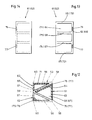
- stiffening elements are arranged on the post 53 in a certain length section and thus at a certain height above the floor.
- one stiffening element 61 can be seen in FIGS. 9 and 10 and the two stiffening elements 62 in FIG. 11.
- the stiffening elements 61 and 62 are matched to the cavities of the M-profile of the post 53 so that they complement this profile to a full profile.
- the plan projection of the stiffening element 61 is an isosceles triangle.
- the plan projection of the two stiffening elements 62 is a right-angled triangle, which is at least approximately equal to one half of the plan projection of the stiffening element 61.
- the stiffening elements 61 and 62 are molded plastic parts.
- the stiffening element 61 has a wall 63 along the narrow side of its plan shape, a wall 64 along one of the long sides of its plan shape, and on both End faces each have a wall 65 and 66 (FIG. 13).
- the open side of the stiffening element 61 is closed by its adjacent central web 57.
- the cavity of the stiffening element 61 present within said walls is divided by a rib or by a plurality of ribs 67 and 68, which are oriented at right angles to the longitudinal extent of the stiffening element 61 and thus at the same time at right angles to the longitudinal axis of the post 53.
- the ribs 67 and 68 extend from the walls 63 and 64 to the long side of the triangular plan shape of the stiffening element 61, so that their outer edge can rest against the central web 57 of the post 53 over the entire length.
- the stiffening elements 62 have the wall 69 on their narrow side, the wall 71 on the one longitudinal side running at right angles thereto and the wall 72 and 73 on each of their end faces. Their cavity is also divided by two ribs 74 and 75, as is the case with the stiffening element 61.
- the elevation projections parallel to the wall 69 of the stiffening elements 62 thus correspond to the corresponding elevation projections of the stiffening element 61, which can be seen in FIGS. 5 and 6.
- the stiffening element 61 there are a few recesses 76 and 77 on the narrower wall 63 in the region of their end walls 65 and 66, or at least in the vicinity of the two outer edges.
- the stiffening elements 62 there are only one recess 78 or 79 on the right-angled edge. These recesses 76 ... 79 are used to fasten the stiffening elements 61 and 62 to a post 53.
- one of these recesses is provided in the area the adjacent edge of the M-profile plastically deformed a small length and thereby into the relevant recess.
- stiffening elements 61 and 62 both in the transverse direction of the Post 53 as well as in its longitudinal direction in the cavity of its M-profile.
- This attachment by positive locking has the advantage that the connection between the stiffening elements 61 and 62 and the post 53 is still ensured even if the post 53 is elastically deformed or if it experiences permanent deformations within certain limits.
- the post 53 is provided at its lower end with an adapter 81, which is designed like the adapter 40 (FIGS. 7 and 8).
- an adapter 81 which is designed like the adapter 40 (FIGS. 7 and 8).
- a cap 82 is placed, which is also designed like the adapter 40.
- This cap 82 increases the connection stiffness and bending stiffness of the upper part of the post 53. It also reduces the risk of injury which could otherwise occur when handling the post with a sharp-edged M profile.
- the adapter 81 and the cap 82 each have a columnar adapter part 85 and two columnar adapter parts 86, which are connected to one another by a base plate 83 and 84, respectively.
- the adapter 81 and the cap 82 are secured in the same way as the stiffening elements 61 and 62, by bending small lengths of the edges of the M-profile of the post 53 into corresponding recesses on the adapter 81 and on the cap 82.
Landscapes
- Engineering & Computer Science (AREA)
- Architecture (AREA)
- Civil Engineering (AREA)
- Structural Engineering (AREA)
- Road Signs Or Road Markings (AREA)
- Near-Field Transmission Systems (AREA)
- Investigating Or Analysing Materials By Optical Means (AREA)
Priority Applications (1)
| Application Number | Priority Date | Filing Date | Title |
|---|---|---|---|
| AT87107584T ATE65813T1 (de) | 1986-05-31 | 1987-05-25 | Bakenstaender. |
Applications Claiming Priority (4)
| Application Number | Priority Date | Filing Date | Title |
|---|---|---|---|
| DE19863618404 DE3618404A1 (de) | 1986-05-31 | 1986-05-31 | Bakenstaender |
| DE3618404 | 1986-05-31 | ||
| DE8706706U DE8706706U1 (es) | 1987-05-09 | 1987-05-09 | |
| DE8706706U | 1987-05-09 |
Publications (3)
| Publication Number | Publication Date |
|---|---|
| EP0248313A2 EP0248313A2 (de) | 1987-12-09 |
| EP0248313A3 EP0248313A3 (en) | 1988-09-07 |
| EP0248313B1 true EP0248313B1 (de) | 1991-07-31 |
Family
ID=25844269
Family Applications (1)
| Application Number | Title | Priority Date | Filing Date |
|---|---|---|---|
| EP87107584A Expired - Lifetime EP0248313B1 (de) | 1986-05-31 | 1987-05-25 | Bakenständer |
Country Status (5)
| Country | Link |
|---|---|
| US (1) | US4799448A (es) |
| EP (1) | EP0248313B1 (es) |
| AT (1) | ATE65813T1 (es) |
| DE (1) | DE3771784D1 (es) |
| ES (1) | ES2025585T3 (es) |
Families Citing this family (7)
| Publication number | Priority date | Publication date | Assignee | Title |
|---|---|---|---|---|
| GB2255998B (en) * | 1991-05-16 | 1995-02-08 | Dee Organ Ltd | Improvements relating to temporary road signs |
| US5606931A (en) * | 1994-08-19 | 1997-03-04 | Rogers; Richard G. | Spot identifying marker |
| US5676350A (en) * | 1994-12-06 | 1997-10-14 | Galli; George | Portable barrier system with portable post mounting device |
| US6117021A (en) | 1996-06-28 | 2000-09-12 | Cobra Golf, Incorporated | Golf club shaft |
| US6349667B1 (en) * | 1999-09-28 | 2002-02-26 | Richard J. Rogers | Location marker |
| US9583027B1 (en) * | 2005-05-09 | 2017-02-28 | Mfp Industries, Llc | Crashworthy portable traffic control sign |
| WO2015186529A1 (ja) * | 2014-06-06 | 2015-12-10 | シャープ株式会社 | 表示装置及びテレビジョン受信機 |
Family Cites Families (15)
| Publication number | Priority date | Publication date | Assignee | Title |
|---|---|---|---|---|
| DE7219360U (de) * | 1973-05-17 | Wolf M | Bake zur Kennzeichnung und Abgrenzung von Fahrwegen | |
| US1830836A (en) * | 1929-04-29 | 1931-11-10 | Bronze Grave Marker Co | Grave marker |
| FR2070486A5 (es) * | 1969-12-05 | 1971-09-10 | Pont A Mousson | |
| US3762674A (en) * | 1971-11-08 | 1973-10-02 | H Ortega | Releasable signpost receptacle |
| FR2307915A1 (fr) * | 1975-04-15 | 1976-11-12 | Sergie Gie Etudes Serv Transpo | Poteau indicateur |
| DE7714570U1 (de) * | 1977-05-07 | 1977-08-18 | Silbernagel, Hermann, 6800 Mannheim | Tragbarer schilderstaender |
| AT370158B (de) * | 1978-10-06 | 1983-03-10 | Hofinger Rudolf | Einrichtung zur verankerung eines stehers als traeger fuer leitschienen, gelaender, verkehrszeichen u.dgl. im boden |
| DE7934718U1 (de) * | 1979-12-10 | 1980-03-20 | Junker, Wilhelm, 7150 Backnang | Fussplatte fuer einen bakenstaender |
| US4461387A (en) * | 1982-08-11 | 1984-07-24 | Belokin Jr Paul | Integral spring clip support assembly for displaying articles |
| DE8301856U1 (de) * | 1983-01-25 | 1983-07-21 | Peter Berghaus GmbH, 5067 Kürten | Verkehrsbake |
| EP0134607A3 (de) * | 1983-08-18 | 1986-02-19 | REHAU AG + Co | Leiteinrichtung zur Baustellensicherung |
| DE3341647A1 (de) * | 1983-11-18 | 1985-05-30 | Dambach-Werke Gmbh, 7560 Gaggenau | Standrohr fuer schilder, insbesondere verkehrsschilder |
| DE8434689U1 (de) * | 1984-11-27 | 1985-02-28 | SPIG Schutzplanken-Produktions-Gesellschaft mbH & Co KG, 6612 Schmelz | Plattenpfosten |
| DE8535843U1 (de) * | 1985-12-20 | 1986-03-06 | Junker, Wilhelm, 7150 Backnang | Pfosten für Verkehrszeichen und Verkehrseinrichtungen |
| DE8614764U1 (de) * | 1986-05-31 | 1986-07-24 | Junker, Wilhelm, 7150 Backnang | Bakenständer |
-
1987
- 1987-05-25 ES ES198787107584T patent/ES2025585T3/es not_active Expired - Lifetime
- 1987-05-25 EP EP87107584A patent/EP0248313B1/de not_active Expired - Lifetime
- 1987-05-25 AT AT87107584T patent/ATE65813T1/de not_active IP Right Cessation
- 1987-05-25 DE DE8787107584T patent/DE3771784D1/de not_active Expired - Lifetime
- 1987-05-29 US US07/055,389 patent/US4799448A/en not_active Expired - Lifetime
Also Published As
| Publication number | Publication date |
|---|---|
| US4799448A (en) | 1989-01-24 |
| EP0248313A3 (en) | 1988-09-07 |
| DE3771784D1 (de) | 1991-09-05 |
| ATE65813T1 (de) | 1991-08-15 |
| EP0248313A2 (de) | 1987-12-09 |
| ES2025585T3 (es) | 1992-04-01 |
Similar Documents
| Publication | Publication Date | Title |
|---|---|---|
| EP3478975B1 (de) | Clip mit einem kopf und einem sich entlang einer längsachse von dem kopf erstreckenden schaft | |
| EP0689628B1 (de) | Leiteinrichtung für leitwände | |
| EP0248313B1 (de) | Bakenständer | |
| EP0351572A2 (de) | Fahrbahntrenneinrichtung | |
| DE3016884A1 (de) | Bakenstaender | |
| DE1784011A1 (de) | Sicherheitsbarriere fuer Autostrassen,Bruecken u.dgl. | |
| DE2720604A1 (de) | Markierungsnagel fuer strassen | |
| DE2840984C2 (de) | Bakenständer | |
| DE3413163C2 (de) | Absperrbake für Verkehrswege | |
| DE202006017431U1 (de) | Übergangskonstruktion mit Betonelementen | |
| EP0355440B1 (de) | Bakenständer | |
| EP1876301B1 (de) | Verbindungsanordnung zwischen einem einen Schutzplankenstrang tragenden Abstandshalter bzw. Distanzstück und einem Pfosten | |
| DE8535843U1 (de) | Pfosten für Verkehrszeichen und Verkehrseinrichtungen | |
| EP0387645B1 (de) | Bakenständer | |
| DE3627146C2 (es) | ||
| DE3411488A1 (de) | Bakenstaender | |
| DE202005008358U1 (de) | Straßenleitpfosten | |
| DE8614764U1 (de) | Bakenständer | |
| DE2949541A1 (de) | Fussplatte fuer einen bakenstaender | |
| DE7828014U1 (de) | Bakenstaender | |
| DE1759160C3 (de) | Straßenleltpfosten | |
| DE3901873A1 (de) | Leiteinrichtung | |
| DE19850251A1 (de) | Verkehrsinsel | |
| DE3618404A1 (de) | Bakenstaender | |
| DE8011966U1 (de) | Bakenstaender |
Legal Events
| Date | Code | Title | Description |
|---|---|---|---|
| PUAI | Public reference made under article 153(3) epc to a published international application that has entered the european phase |
Free format text: ORIGINAL CODE: 0009012 |
|
| AK | Designated contracting states |
Kind code of ref document: A2 Designated state(s): AT BE CH DE ES FR GB IT LI NL SE |
|
| PUAL | Search report despatched |
Free format text: ORIGINAL CODE: 0009013 |
|
| AK | Designated contracting states |
Kind code of ref document: A3 Designated state(s): AT BE CH DE ES FR GB IT LI NL SE |
|
| 17P | Request for examination filed |
Effective date: 19890304 |
|
| 17Q | First examination report despatched |
Effective date: 19900509 |
|
| GRAA | (expected) grant |
Free format text: ORIGINAL CODE: 0009210 |
|
| AK | Designated contracting states |
Kind code of ref document: B1 Designated state(s): AT BE CH DE ES FR GB IT LI NL SE |
|
| REF | Corresponds to: |
Ref document number: 65813 Country of ref document: AT Date of ref document: 19910815 Kind code of ref document: T |
|
| REF | Corresponds to: |
Ref document number: 3771784 Country of ref document: DE Date of ref document: 19910905 |
|
| ITF | It: translation for a ep patent filed |
Owner name: MODIANO & ASSOCIATI S.R.L. |
|
| ET | Fr: translation filed | ||
| GBT | Gb: translation of ep patent filed (gb section 77(6)(a)/1977) | ||
| REG | Reference to a national code |
Ref country code: ES Ref legal event code: FG2A Ref document number: 2025585 Country of ref document: ES Kind code of ref document: T3 |
|
| PLBE | No opposition filed within time limit |
Free format text: ORIGINAL CODE: 0009261 |
|
| STAA | Information on the status of an ep patent application or granted ep patent |
Free format text: STATUS: NO OPPOSITION FILED WITHIN TIME LIMIT |
|
| 26N | No opposition filed | ||
| EAL | Se: european patent in force in sweden |
Ref document number: 87107584.2 |
|
| REG | Reference to a national code |
Ref country code: GB Ref legal event code: IF02 |
|
| PGFP | Annual fee paid to national office [announced via postgrant information from national office to epo] |
Ref country code: SE Payment date: 20030505 Year of fee payment: 17 |
|
| PGFP | Annual fee paid to national office [announced via postgrant information from national office to epo] |
Ref country code: AT Payment date: 20030516 Year of fee payment: 17 |
|
| PGFP | Annual fee paid to national office [announced via postgrant information from national office to epo] |
Ref country code: GB Payment date: 20030519 Year of fee payment: 17 Ref country code: BE Payment date: 20030519 Year of fee payment: 17 |
|
| PGFP | Annual fee paid to national office [announced via postgrant information from national office to epo] |
Ref country code: CH Payment date: 20030527 Year of fee payment: 17 |
|
| PGFP | Annual fee paid to national office [announced via postgrant information from national office to epo] |
Ref country code: NL Payment date: 20030528 Year of fee payment: 17 Ref country code: FR Payment date: 20030528 Year of fee payment: 17 |
|
| PGFP | Annual fee paid to national office [announced via postgrant information from national office to epo] |
Ref country code: ES Payment date: 20030530 Year of fee payment: 17 |
|
| PGFP | Annual fee paid to national office [announced via postgrant information from national office to epo] |
Ref country code: DE Payment date: 20030531 Year of fee payment: 17 |
|
| PG25 | Lapsed in a contracting state [announced via postgrant information from national office to epo] |
Ref country code: GB Free format text: LAPSE BECAUSE OF NON-PAYMENT OF DUE FEES Effective date: 20040525 Ref country code: AT Free format text: LAPSE BECAUSE OF NON-PAYMENT OF DUE FEES Effective date: 20040525 |
|
| PG25 | Lapsed in a contracting state [announced via postgrant information from national office to epo] |
Ref country code: SE Free format text: LAPSE BECAUSE OF NON-PAYMENT OF DUE FEES Effective date: 20040526 Ref country code: ES Free format text: LAPSE BECAUSE OF NON-PAYMENT OF DUE FEES Effective date: 20040526 |
|
| PG25 | Lapsed in a contracting state [announced via postgrant information from national office to epo] |
Ref country code: LI Free format text: LAPSE BECAUSE OF NON-PAYMENT OF DUE FEES Effective date: 20040531 Ref country code: CH Free format text: LAPSE BECAUSE OF NON-PAYMENT OF DUE FEES Effective date: 20040531 Ref country code: BE Free format text: LAPSE BECAUSE OF NON-PAYMENT OF DUE FEES Effective date: 20040531 |
|
| BERE | Be: lapsed |
Owner name: *JUNKER WILHELM Effective date: 20040531 |
|
| PG25 | Lapsed in a contracting state [announced via postgrant information from national office to epo] |
Ref country code: NL Free format text: LAPSE BECAUSE OF NON-PAYMENT OF DUE FEES Effective date: 20041201 Ref country code: DE Free format text: LAPSE BECAUSE OF NON-PAYMENT OF DUE FEES Effective date: 20041201 |
|
| EUG | Se: european patent has lapsed | ||
| GBPC | Gb: european patent ceased through non-payment of renewal fee |
Effective date: 20040525 |
|
| REG | Reference to a national code |
Ref country code: CH Ref legal event code: PL |
|
| PG25 | Lapsed in a contracting state [announced via postgrant information from national office to epo] |
Ref country code: FR Free format text: LAPSE BECAUSE OF NON-PAYMENT OF DUE FEES Effective date: 20050131 |
|
| NLV4 | Nl: lapsed or anulled due to non-payment of the annual fee |
Effective date: 20041201 |
|
| REG | Reference to a national code |
Ref country code: FR Ref legal event code: ST |
|
| PG25 | Lapsed in a contracting state [announced via postgrant information from national office to epo] |
Ref country code: IT Free format text: LAPSE BECAUSE OF NON-PAYMENT OF DUE FEES;WARNING: LAPSES OF ITALIAN PATENTS WITH EFFECTIVE DATE BEFORE 2007 MAY HAVE OCCURRED AT ANY TIME BEFORE 2007. THE CORRECT EFFECTIVE DATE MAY BE DIFFERENT FROM THE ONE RECORDED. Effective date: 20050525 |
|
| REG | Reference to a national code |
Ref country code: ES Ref legal event code: FD2A Effective date: 20040526 |