EP0248181A1 - Boîte de fusibles et de distribution pour véhicules à moteur - Google Patents
Boîte de fusibles et de distribution pour véhicules à moteur Download PDFInfo
- Publication number
- EP0248181A1 EP0248181A1 EP87105694A EP87105694A EP0248181A1 EP 0248181 A1 EP0248181 A1 EP 0248181A1 EP 87105694 A EP87105694 A EP 87105694A EP 87105694 A EP87105694 A EP 87105694A EP 0248181 A1 EP0248181 A1 EP 0248181A1
- Authority
- EP
- European Patent Office
- Prior art keywords
- fuse
- distribution box
- cable
- box according
- recesses
- Prior art date
- Legal status (The legal status is an assumption and is not a legal conclusion. Google has not performed a legal analysis and makes no representation as to the accuracy of the status listed.)
- Granted
Links
Images

Classifications
-
- H—ELECTRICITY
- H02—GENERATION; CONVERSION OR DISTRIBUTION OF ELECTRIC POWER
- H02G—INSTALLATION OF ELECTRIC CABLES OR LINES, OR OF COMBINED OPTICAL AND ELECTRIC CABLES OR LINES
- H02G3/00—Installations of electric cables or lines or protective tubing therefor in or on buildings, equivalent structures or vehicles
- H02G3/02—Details
- H02G3/08—Distribution boxes; Connection or junction boxes
- H02G3/088—Dustproof, splashproof, drip-proof, waterproof, or flameproof casings or inlets
Definitions
- the invention relates to a fuse and distribution box for motor vehicles according to the preamble of claim 1.
- the fuse and distribution box primarily serves to hold the entire central electrical system of the motor vehicle and is often accommodated in a so-called water box located in the engine compartment and adjacent to the passenger compartment. Among other things, this is intended to ensure that the central electrical system of the fuse and distribution box, which is watertight towards the outside, is protected against dirt and similar influences which impair the function of the integrated electrical components. From the passenger compartment as well as from the engine compartment, various cable sets open into the fuse and distribution box, from where the control of the individual functional elements is carried out. While the supply of the lines from the passenger compartment does not pose any significant problems, it is absolutely necessary to take appropriate measures for the line sets that open out from the engine compartment so that dirt, engine gases or the like cannot penetrate the passage points of the lines through the water tank. This is because the heating and ventilation device for the passenger compartment is usually installed in the water tank.
- the cable sets with the corresponding plugs are led through often quite small holes through the front wall into the interior and from there into the water box and then connected to the fuse and distribution box.
- Another disadvantage is that the relevant line penetrations must be sealed by suitable measures. Will be with a subsequent addition of the equipment in the vehicle electrical system, additional cable connections are required, so it is usually not possible to pass these cable sets through the existing holes in the end wall, so that additional cable openings must be created.
- the present invention is intended to remedy this situation.
- the invention is therefore based on the object of designing a fuse and distribution box for motor vehicles in such a way that the connection, in particular of the line sets opening out from the engine compartment, can be carried out in a simple manner and without sealing problems and that more flexibility can also be achieved in that additional, d. H. previously not provided line sets can be connected without difficulty.
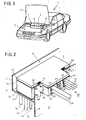
- Fig. 1 shows a passenger vehicle (1) with the hood (2) folded up so that an engine compartment (3) is visible. This is closed off to the side and to the front by the body boundary walls, while a further partition wall (4) delimits the passenger compartment (5).
- a closed area a so-called “water tank” (7), is formed by a further partition wall (6) upstream of the partition wall (4) and extending approximately over the width of the engine compartment (3). This is sealed in particular with respect to the engine compartment (3) in such a way that engine gases or similar contaminants cannot penetrate from there.
- the water tank (7) is particularly suitable for storing a safe tion and distribution box (8), in which various lines, for example from consumers in the engine compartment (3) and from various operating and display instruments of the passenger compartment (5) open.
- the fuse and distribution box (8) is essentially designed as an approximately cuboid box which has a stem (9). This stem (9) protrudes from a dimensionally adapted cutout (10) of the front partition (6) and thus into the engine compartment (3). A circumferential sealing strip (13) provided in the area of the cutout (10) prevents gases and dirt from entering the engine compartment into the water tank (7) via this cutout (10).
- the fuse and distribution box (8) is formed in two parts, consisting of the actual housing (14) and a cover (15). Here too, a circumferential sealing strip (20) is provided between the two.
- cable strands (16-18) coming from the passenger compartment (5) and opening into the fuse and distribution box (8) can open into the water box (7) from below. They serve to supply operating and display instruments provided in the passenger compartment (5), such as lighting, power windows, heating, etc.
- These wiring harnesses (16 to 18) can be led through a corresponding opening in the central electrical system of the fuse and distribution box (8).
- Another circumferential sealing band (41) also prevents dirt from penetrating into this area.
- the front end face (19) of the housing (14) protruding into the engine compartment (3) has, as can be seen in particular from the others 3 to 5 shows a number of recesses (22-24).
- a number of cable grommets (25, 26) are inserted from above with the cover (15) removed, whereby they each grip the aforementioned recesses (22-24) on both sides and with one another in the manner of a groove and Spring connection (27) are plugged together. An optimal sealing effect can thus be achieved.
- Cable strands (29, 30) coming from consumers arranged in the engine compartment (3) are now guided through the outer cable grommets (25, 26) into the fuse and distribution box (8). Cables for additional electrical equipment can be routed through the central recess (23). If no cables are provided, the cable grommets are designed as blind plugs (28). If retrofitting is necessary, they can be exchanged for others at any time, so that the retrofitting work can be carried out in a particularly simple manner.
- the cable strands (29, 30) open as plug connections (33, 34) in a removable inner part (35) of the fuse and distribution box (8).
- a number of fuses (36) and relays (37, 38) are housed on a circuit board.
- the cable harnesses (16-18) coming, for example, from the passenger compartment (5) and opening into the fuse and distribution box (8) could also be led into the engine compartment (3) through the cable grommets (25, 26) used in the stem (9) be connected or with lines that lead from the engine compartment into the central electrical system.
- the entire fuse and distribution box (8) is thus designed to be extremely flexible with regard to the additional equipment to be provided, and there are also favorable conditions with regard to assembly and maintenance work.
- the summary sen of the entire central electrical system can thus also be carried out in a particularly simple manner.
- optimal protection of the integrated components (36 to 38) is guaranteed.
- the fuse and distribution box (8) which is then designed as a supporting part, for increasing the rigidity of the partition wall (6), which extends approximately over the width of the engine compartment (3).
- a strength-related coupling of the two components (6, 8) can be brought about via screw connections (42) or similarly acting connection techniques.
- the fuse and distribution box (8) would fit snugly against the partition (6) with its front face.
- the seal (13) could possibly be omitted.
Landscapes
- Engineering & Computer Science (AREA)
- Architecture (AREA)
- Civil Engineering (AREA)
- Structural Engineering (AREA)
- Fuses (AREA)
- Installation Of Indoor Wiring (AREA)
Applications Claiming Priority (2)
| Application Number | Priority Date | Filing Date | Title |
|---|---|---|---|
| DE19863619183 DE3619183A1 (de) | 1986-06-06 | 1986-06-06 | Sicherungs- und verteilerkasten fuer kraftfahrzeuge |
| DE3619183 | 1986-06-06 |
Publications (2)
| Publication Number | Publication Date |
|---|---|
| EP0248181A1 true EP0248181A1 (fr) | 1987-12-09 |
| EP0248181B1 EP0248181B1 (fr) | 1990-06-27 |
Family
ID=6302501
Family Applications (1)
| Application Number | Title | Priority Date | Filing Date |
|---|---|---|---|
| EP87105694A Expired - Lifetime EP0248181B1 (fr) | 1986-06-06 | 1987-04-16 | Boîte de fusibles et de distribution pour véhicules à moteur |
Country Status (3)
| Country | Link |
|---|---|
| EP (1) | EP0248181B1 (fr) |
| JP (1) | JPS63931A (fr) |
| DE (2) | DE3619183A1 (fr) |
Cited By (14)
| Publication number | Priority date | Publication date | Assignee | Title |
|---|---|---|---|---|
| EP0368115A2 (fr) * | 1988-11-09 | 1990-05-16 | Grote & Hartmann GmbH & Co. KG | Comprimé buccal |
| AT394690B (de) * | 1991-01-14 | 1992-05-25 | Uher Ag | Schaltkreisanordnung fuer bordnetze von fahrzeugen |
| EP0340444B1 (fr) * | 1988-05-03 | 1992-08-12 | Dicon Dinkel Industrie Automation Gmbh | Boîtier pour des équipments électriques ou électroniques |
| EP0543350A1 (fr) * | 1991-11-22 | 1993-05-26 | RXS Schrumpftechnik-Garnituren GmbH | Manchon de câble comprenant un boîtier divisé longitudinalement |
| WO1994019213A1 (fr) * | 1993-02-24 | 1994-09-01 | Siemens Aktiengesellschaft | Dispositif de distribution pour composants electriques |
| WO1996000156A1 (fr) * | 1994-06-23 | 1996-01-04 | United Technologies Automotive, Inc. | Boitier et systeme de distribution electrique |
| US5574259A (en) * | 1993-12-22 | 1996-11-12 | Rxs Schrumpftechnik-Garnituren Gmbh | Cable sleeve composed of a longitudinally divided housing |
| US5785532A (en) * | 1993-06-09 | 1998-07-28 | United Technologies Automotive, Inc. | Power distribution box and system |
| US5805402A (en) * | 1993-06-09 | 1998-09-08 | Ut Automotive Dearborn, Inc. | Integrated interior trim and electrical assembly for an automotive vehicle |
| WO1998046458A1 (fr) * | 1997-04-15 | 1998-10-22 | Temic Telefunken Microelectronic Gmbh | Boitier |
| EP0920083A1 (fr) * | 1997-11-25 | 1999-06-02 | Sumitomo Wiring Systems, Ltd. | Assemblage de connexion électrique avec un bloc de jonction ayant une face laterale prolongée |
| DE102018221627A1 (de) * | 2018-12-13 | 2020-06-18 | Icotek Project Gmbh & Co. Kg | Kabeldurchführung für einen Durchbruch in einer Platte |
| EP3584898B1 (fr) * | 2018-06-20 | 2022-12-14 | Kaiser GmbH & Co. KG | Boîte d'installation |
| DE102021126007A1 (de) | 2021-10-07 | 2023-04-13 | Icotek Project Gmbh & Co. Kg | Kabeldurchführung |
Families Citing this family (20)
| Publication number | Priority date | Publication date | Assignee | Title |
|---|---|---|---|---|
| DE3732087C1 (en) * | 1987-09-24 | 1988-12-29 | Opel Adam Ag | Combined arrangement of electrical and electronic components, especially fuses and relays for motor vehicles |
| DE4041016C1 (fr) * | 1990-12-20 | 1992-07-16 | Audi Ag, 8070 Ingolstadt, De | |
| DE4341384C2 (de) * | 1992-12-17 | 2002-12-12 | Volkswagen Ag | Durchführung von Leitungen |
| DE19544236B4 (de) * | 1994-12-17 | 2005-05-19 | Volkswagen Ag | Anordnung für ein Bordnetz eines Kraftfahrzeuges |
| DE19524120C1 (de) * | 1995-07-03 | 1996-08-14 | Opel Adam Ag | Abdeckung für einen Wasserkasten eines Kraftfahrzeuges |
| DE19653733C2 (de) * | 1996-12-12 | 1999-11-11 | Brose Fahrzeugteile | Vorrichtung zur Herstellung einer elektrischen Steckverbindung zwischen elektrischen oder elektronischen Bauteilen oder Baugruppen |
| DE19850794C1 (de) * | 1998-11-04 | 2000-02-17 | Opel Adam Ag | Kraftfahrzeug mit einem Sicherungskasten |
| DE19936887A1 (de) * | 1999-08-05 | 2001-02-01 | Daimler Chrysler Ag | Vorrichtung zur Befestigung von elektronischen Steuergeräten |
| DE19936880A1 (de) * | 1999-08-05 | 2001-02-01 | Daimler Chrysler Ag | Vorrichtung zur Aufnahme von Steuergeräten |
| DE19943867A1 (de) * | 1999-09-13 | 2001-04-19 | Bosch Gmbh Robert | Elektrotechnische Baugruppe für ein Kraftfahrzeug |
| JP3536794B2 (ja) | 1999-10-19 | 2004-06-14 | トヨタ自動車株式会社 | 電装部品の配置構造 |
| DE19959185A1 (de) * | 1999-12-08 | 2001-06-28 | Bethke Kunststofftechnik Gmbh | Kabeldurchführung |
| DE10300464A1 (de) * | 2003-01-07 | 2004-07-15 | Intedis Gmbh & Co. Kg | Bordnetz eines Kraftfahrzeugs |
| DE10313989B4 (de) | 2003-03-27 | 2012-07-12 | Murrplastik Systemtechnik Gmbh | Kabeldurchführungsvorrichtung |
| DE10349996B4 (de) * | 2003-10-24 | 2013-09-05 | Icotek Project Gmbh & Co. Kg | Tülle |
| DE102009060988B3 (de) * | 2009-11-12 | 2011-05-19 | Icotek Project Gmbh & Co. Kg | Kabeltrageinheit |
| DE202012101639U1 (de) | 2012-05-03 | 2013-08-06 | Weidmüller Interface GmbH & Co. KG | Durchführungsgehäuse |
| IT201900000034A1 (it) | 2019-01-03 | 2020-07-03 | Detas S P A | Assieme di passacavo per il passaggio e la guida di un cavo |
| IT202100006518A1 (it) | 2021-03-18 | 2022-09-18 | Detas S P A | Assieme di passacavo per il passaggio e la guida di un cavo |
| DE102021208790A1 (de) | 2021-08-11 | 2023-02-16 | Zf Friedrichshafen Ag | Gehäuse für ein Steuergerät |
Citations (8)
| Publication number | Priority date | Publication date | Assignee | Title |
|---|---|---|---|---|
| US1424691A (en) * | 1919-06-06 | 1922-08-01 | Tasso Charles | Gasket |
| DE7424619U (de) * | 1973-12-05 | 1975-01-09 | Cavis Cavetti Isolati Spa | Verkabelungsgehäuse für ein Kraftfahrzeug |
| DE2606319A1 (de) * | 1976-02-18 | 1977-08-25 | Rau Swf Autozubehoer | Zentralelektrik fuer fahrzeuge |
| US4047787A (en) * | 1977-01-21 | 1977-09-13 | Northern Telecom Limited | Extension cords for plug-in telephones |
| DE2748872A1 (de) * | 1977-11-02 | 1979-05-03 | Wolfgang Freitag | Zweiteiliges gehaeuse fuer anzuschliessende koaxialkabel |
| DE2827106A1 (de) * | 1978-06-21 | 1980-01-10 | Festo Maschf Stoll G | Gehaeuse zur aufnahme von elektrotechnischen oder elektronischen geraeten mit einer vielfach-kabelabdichtung-, kabelzugentlastung und -kabelschirmkontaktierung |
| EP0041583A1 (fr) * | 1980-06-10 | 1981-12-16 | Schorch GmbH | Boîte de connexion sans bagues d'étanchéité pour machines électriques |
| DE3032249A1 (de) * | 1980-08-27 | 1982-04-01 | Jean Müller KG Elektrotechnische Fabrik, 6228 Eltville | Einrichtung fuer loesbare zuleitungs-anbringung |
Family Cites Families (3)
| Publication number | Priority date | Publication date | Assignee | Title |
|---|---|---|---|---|
| BE788705A (fr) * | 1971-12-03 | 1973-01-02 | Formex Mfg Inc | Termineur de conduit |
| DE8215324U1 (de) * | 1981-11-26 | 1982-09-09 | Rudolf Döpfl GmbH Brandschutz- und Sicherheitstechnik, 1232 Wien | Preßplatte für die Spanneinrichtung einer Kabeldurchführung |
| DE8321980U1 (de) * | 1983-07-30 | 1983-12-15 | Christian Geyer GmbH & Co, 8500 Nürnberg | Hausanschlußkasten |
-
1986
- 1986-06-06 DE DE19863619183 patent/DE3619183A1/de active Granted
-
1987
- 1987-04-16 EP EP87105694A patent/EP0248181B1/fr not_active Expired - Lifetime
- 1987-04-16 DE DE8787105694T patent/DE3763389D1/de not_active Expired - Fee Related
- 1987-05-27 JP JP62133250A patent/JPS63931A/ja active Pending
Patent Citations (8)
| Publication number | Priority date | Publication date | Assignee | Title |
|---|---|---|---|---|
| US1424691A (en) * | 1919-06-06 | 1922-08-01 | Tasso Charles | Gasket |
| DE7424619U (de) * | 1973-12-05 | 1975-01-09 | Cavis Cavetti Isolati Spa | Verkabelungsgehäuse für ein Kraftfahrzeug |
| DE2606319A1 (de) * | 1976-02-18 | 1977-08-25 | Rau Swf Autozubehoer | Zentralelektrik fuer fahrzeuge |
| US4047787A (en) * | 1977-01-21 | 1977-09-13 | Northern Telecom Limited | Extension cords for plug-in telephones |
| DE2748872A1 (de) * | 1977-11-02 | 1979-05-03 | Wolfgang Freitag | Zweiteiliges gehaeuse fuer anzuschliessende koaxialkabel |
| DE2827106A1 (de) * | 1978-06-21 | 1980-01-10 | Festo Maschf Stoll G | Gehaeuse zur aufnahme von elektrotechnischen oder elektronischen geraeten mit einer vielfach-kabelabdichtung-, kabelzugentlastung und -kabelschirmkontaktierung |
| EP0041583A1 (fr) * | 1980-06-10 | 1981-12-16 | Schorch GmbH | Boîte de connexion sans bagues d'étanchéité pour machines électriques |
| DE3032249A1 (de) * | 1980-08-27 | 1982-04-01 | Jean Müller KG Elektrotechnische Fabrik, 6228 Eltville | Einrichtung fuer loesbare zuleitungs-anbringung |
Cited By (18)
| Publication number | Priority date | Publication date | Assignee | Title |
|---|---|---|---|---|
| EP0340444B1 (fr) * | 1988-05-03 | 1992-08-12 | Dicon Dinkel Industrie Automation Gmbh | Boîtier pour des équipments électriques ou électroniques |
| EP0368115A3 (fr) * | 1988-11-09 | 1991-01-02 | Grote & Hartmann GmbH & Co. KG | Comprimé buccal |
| EP0368115A2 (fr) * | 1988-11-09 | 1990-05-16 | Grote & Hartmann GmbH & Co. KG | Comprimé buccal |
| AT394690B (de) * | 1991-01-14 | 1992-05-25 | Uher Ag | Schaltkreisanordnung fuer bordnetze von fahrzeugen |
| EP0543350A1 (fr) * | 1991-11-22 | 1993-05-26 | RXS Schrumpftechnik-Garnituren GmbH | Manchon de câble comprenant un boîtier divisé longitudinalement |
| US5313018A (en) * | 1991-11-22 | 1994-05-17 | Rxs Schrumpftechnik-Garnituren Gmbh | Cable sleeve composed of a longitudinally-divided housing |
| WO1994019213A1 (fr) * | 1993-02-24 | 1994-09-01 | Siemens Aktiengesellschaft | Dispositif de distribution pour composants electriques |
| US5785532A (en) * | 1993-06-09 | 1998-07-28 | United Technologies Automotive, Inc. | Power distribution box and system |
| US5805402A (en) * | 1993-06-09 | 1998-09-08 | Ut Automotive Dearborn, Inc. | Integrated interior trim and electrical assembly for an automotive vehicle |
| US5574259A (en) * | 1993-12-22 | 1996-11-12 | Rxs Schrumpftechnik-Garnituren Gmbh | Cable sleeve composed of a longitudinally divided housing |
| WO1996000156A1 (fr) * | 1994-06-23 | 1996-01-04 | United Technologies Automotive, Inc. | Boitier et systeme de distribution electrique |
| WO1998046458A1 (fr) * | 1997-04-15 | 1998-10-22 | Temic Telefunken Microelectronic Gmbh | Boitier |
| US6180875B1 (en) | 1997-04-15 | 2001-01-30 | Temic Telefunken Microelectronic Gmbh | Housing |
| EP0920083A1 (fr) * | 1997-11-25 | 1999-06-02 | Sumitomo Wiring Systems, Ltd. | Assemblage de connexion électrique avec un bloc de jonction ayant une face laterale prolongée |
| US6010341A (en) * | 1997-11-25 | 2000-01-04 | Sumitomo Wiring Systems, Ltd. | Electrical connection unit with a junction block or main box having an extended side wall |
| EP3584898B1 (fr) * | 2018-06-20 | 2022-12-14 | Kaiser GmbH & Co. KG | Boîte d'installation |
| DE102018221627A1 (de) * | 2018-12-13 | 2020-06-18 | Icotek Project Gmbh & Co. Kg | Kabeldurchführung für einen Durchbruch in einer Platte |
| DE102021126007A1 (de) | 2021-10-07 | 2023-04-13 | Icotek Project Gmbh & Co. Kg | Kabeldurchführung |
Also Published As
| Publication number | Publication date |
|---|---|
| JPS63931A (ja) | 1988-01-05 |
| DE3763389D1 (de) | 1990-08-02 |
| EP0248181B1 (fr) | 1990-06-27 |
| DE3619183A1 (de) | 1987-12-10 |
| DE3619183C2 (fr) | 1989-10-05 |
Similar Documents
| Publication | Publication Date | Title |
|---|---|---|
| EP0248181B1 (fr) | Boîte de fusibles et de distribution pour véhicules à moteur | |
| DE102018205914B4 (de) | Elektrischer Anschlusskasten und Kabelbaum | |
| EP0909898B1 (fr) | Unité d'entretien pour l'air comprimé | |
| DE10113627B4 (de) | Schaltschranküberwachungseinrichtung | |
| DE3530413A1 (de) | Bausatzteil fuer die verlegung elektrischer leitungen in kraftfahrzeugen | |
| DE3732087C1 (en) | Combined arrangement of electrical and electronic components, especially fuses and relays for motor vehicles | |
| DE3609609C2 (fr) | ||
| DE10255490A1 (de) | Haltevorrichtung und Gerät für Haltevorrichtung | |
| DE10084595B4 (de) | Elektrischer Anschlusskasten | |
| EP0584444A1 (fr) | Elément de montage pour canal d'installation | |
| DE102009022645B4 (de) | Klemmendeckel für einen Elektrizitätszähler und Elektrizitätszähler sowie Verfahren zur Ausrüstung eines Elektrizitätszählers | |
| EP0650228A2 (fr) | Dispositif de fermeture d'une ouverture dans un boîte | |
| DE19928400C2 (de) | Berührungssichere elektrische Hochspannungsversorgung | |
| EP1569250A2 (fr) | Transformateur de courant et ensemble comprenant un appareil électrique | |
| EP0669794B1 (fr) | Boítier constitué d'une base et d'un cache | |
| EP0355524B1 (fr) | Canalisation pour câble | |
| EP2026429A1 (fr) | Commutateur de séparation de sécurité basse tension doté de pinces à crochets entièrement revêtues | |
| AT523766B1 (de) | Berührschutz für ein Prüfkabel | |
| WO2006131014A1 (fr) | Unite fonctionnelle pour appareil electrique ou electronique | |
| EP0835048A2 (fr) | Boítier pour un système à plusieurs canaux | |
| DE19817945C1 (de) | Schrank mit mindestens einem eingebauten elektrischen Gerät | |
| DE2340773A1 (de) | Uebergabesteckverbindung | |
| EP1361155B1 (fr) | Unité de commande et/ou de visualisation pour véhicules | |
| DE19854584B4 (de) | Elektrische Installationsgeräte, insbesondere Schutzkontaktsteckdosenanordnungen | |
| DE2900357A1 (de) | Ueberbrueckungseinrichtung fuer einen elektrozaehler |
Legal Events
| Date | Code | Title | Description |
|---|---|---|---|
| PUAI | Public reference made under article 153(3) epc to a published international application that has entered the european phase |
Free format text: ORIGINAL CODE: 0009012 |
|
| 17P | Request for examination filed |
Effective date: 19870416 |
|
| AK | Designated contracting states |
Kind code of ref document: A1 Designated state(s): DE FR GB IT |
|
| 17Q | First examination report despatched |
Effective date: 19890810 |
|
| ITF | It: translation for a ep patent filed |
Owner name: DE DOMINICIS & MAYER S.R.L. |
|
| GRAA | (expected) grant |
Free format text: ORIGINAL CODE: 0009210 |
|
| AK | Designated contracting states |
Kind code of ref document: B1 Designated state(s): DE FR GB IT |
|
| REF | Corresponds to: |
Ref document number: 3763389 Country of ref document: DE Date of ref document: 19900802 |
|
| GBT | Gb: translation of ep patent filed (gb section 77(6)(a)/1977) | ||
| ET | Fr: translation filed | ||
| PLBE | No opposition filed within time limit |
Free format text: ORIGINAL CODE: 0009261 |
|
| STAA | Information on the status of an ep patent application or granted ep patent |
Free format text: STATUS: NO OPPOSITION FILED WITHIN TIME LIMIT |
|
| ITTA | It: last paid annual fee | ||
| 26N | No opposition filed | ||
| PGFP | Annual fee paid to national office [announced via postgrant information from national office to epo] |
Ref country code: GB Payment date: 19950320 Year of fee payment: 9 |
|
| PGFP | Annual fee paid to national office [announced via postgrant information from national office to epo] |
Ref country code: FR Payment date: 19950404 Year of fee payment: 9 |
|
| PG25 | Lapsed in a contracting state [announced via postgrant information from national office to epo] |
Ref country code: GB Effective date: 19960416 |
|
| GBPC | Gb: european patent ceased through non-payment of renewal fee |
Effective date: 19960416 |
|
| PG25 | Lapsed in a contracting state [announced via postgrant information from national office to epo] |
Ref country code: FR Effective date: 19961227 |
|
| REG | Reference to a national code |
Ref country code: FR Ref legal event code: ST |
|
| PGFP | Annual fee paid to national office [announced via postgrant information from national office to epo] |
Ref country code: DE Payment date: 19980403 Year of fee payment: 12 |
|
| PG25 | Lapsed in a contracting state [announced via postgrant information from national office to epo] |
Ref country code: DE Free format text: LAPSE BECAUSE OF NON-PAYMENT OF DUE FEES Effective date: 20000201 |
|
| PG25 | Lapsed in a contracting state [announced via postgrant information from national office to epo] |
Ref country code: IT Free format text: LAPSE BECAUSE OF NON-PAYMENT OF DUE FEES;WARNING: LAPSES OF ITALIAN PATENTS WITH EFFECTIVE DATE BEFORE 2007 MAY HAVE OCCURRED AT ANY TIME BEFORE 2007. THE CORRECT EFFECTIVE DATE MAY BE DIFFERENT FROM THE ONE RECORDED. Effective date: 20050416 |