EP0543350A1 - Manchon de câble comprenant un boîtier divisé longitudinalement - Google Patents
Manchon de câble comprenant un boîtier divisé longitudinalement Download PDFInfo
- Publication number
- EP0543350A1 EP0543350A1 EP92119642A EP92119642A EP0543350A1 EP 0543350 A1 EP0543350 A1 EP 0543350A1 EP 92119642 A EP92119642 A EP 92119642A EP 92119642 A EP92119642 A EP 92119642A EP 0543350 A1 EP0543350 A1 EP 0543350A1
- Authority
- EP
- European Patent Office
- Prior art keywords
- cable
- cable sleeve
- sealing
- sleeve according
- parting plane
- Prior art date
- Legal status (The legal status is an assumption and is not a legal conclusion. Google has not performed a legal analysis and makes no representation as to the accuracy of the status listed.)
- Granted
Links
Images


Classifications
-
- H—ELECTRICITY
- H02—GENERATION; CONVERSION OR DISTRIBUTION OF ELECTRIC POWER
- H02G—INSTALLATION OF ELECTRIC CABLES OR LINES, OR OF COMBINED OPTICAL AND ELECTRIC CABLES OR LINES
- H02G15/00—Cable fittings
- H02G15/08—Cable junctions
- H02G15/18—Cable junctions protected by sleeves, e.g. for communication cable
- H02G15/192—Cable junctions protected by sleeves, e.g. for communication cable with support means for ends of the sleeves
-
- G—PHYSICS
- G02—OPTICS
- G02B—OPTICAL ELEMENTS, SYSTEMS OR APPARATUS
- G02B6/00—Light guides; Structural details of arrangements comprising light guides and other optical elements, e.g. couplings
- G02B6/44—Mechanical structures for providing tensile strength and external protection for fibres, e.g. optical transmission cables
- G02B6/4439—Auxiliary devices
- G02B6/444—Systems or boxes with surplus lengths
- G02B6/4441—Boxes
- G02B6/4446—Cable boxes, e.g. splicing boxes with two or more multi fibre cables
- G02B6/4447—Cable boxes, e.g. splicing boxes with two or more multi fibre cables with divided shells
-
- H—ELECTRICITY
- H02—GENERATION; CONVERSION OR DISTRIBUTION OF ELECTRIC POWER
- H02G—INSTALLATION OF ELECTRIC CABLES OR LINES, OR OF COMBINED OPTICAL AND ELECTRIC CABLES OR LINES
- H02G15/00—Cable fittings
- H02G15/013—Sealing means for cable inlets
-
- H—ELECTRICITY
- H02—GENERATION; CONVERSION OR DISTRIBUTION OF ELECTRIC POWER
- H02G—INSTALLATION OF ELECTRIC CABLES OR LINES, OR OF COMBINED OPTICAL AND ELECTRIC CABLES OR LINES
- H02G15/00—Cable fittings
- H02G15/08—Cable junctions
- H02G15/10—Cable junctions protected by boxes, e.g. by distribution, connection or junction boxes
- H02G15/113—Boxes split longitudinally in main cable direction
Definitions
- the invention relates to a cable sleeve made of a longitudinally divided housing with a sealing system in the parting plane of the housing and with front cable entry areas.
- the present invention has for its object to provide a cable sleeve with longitudinal division, in which the cable entry areas can remain untouched when opened later.
- the object is achieved according to the invention with a cable sleeve of the type described in the introduction in that a further separation level, which is independent of the housing separation level, is provided in the cable entry areas, in which the cable entry openings are introduced.
- the parting plane of the half-shells lies at the same time in the parting plane of the cables to be inserted, so that when the cable socket is opened, the seals in the cable entry areas are also affected.
- the cable entry areas are also opened. This very often leads to irreversible damage to the cable seal, so that the cable sleeve is no longer tight in these areas after reclosing. The Seals must therefore be completely replaced, which means a great deal of effort.
- the invention is a cable sleeve with a separate sealing area for the cable entries, and the use on uncut cables is also possible without using shrink technology.
- This solution provides a second parting plane in which the cables to be inserted are arranged.
- This second parting plane is covered by an adapted sealing body with one of its longitudinal surfaces, the height of the sealing body being dimensioned such that the longitudinal surface opposite the first surface forms the first parting plane with the boundary surfaces of the sleeve half-shell. In this way, this separation level is separate from the cable entry level and when opening the cable sleeve, the cable entry level can remain unaffected.
- the cables to be inserted are wrapped with plastic or elastic sealing material and inserted into the provided troughs or insertion openings of the second parting level in the cable sleeve.
- the cable entry openings can be preformed at the factory or made at the assembly point, for example by drilling or breaking out.
- Sealing inserts which can be snapped in and out can also be provided in the provided insertion openings, which can be made of rubber or other elastic material, for example. These sealing inserts can also be used by means of glue or sealing paste, which have corresponding insertion diameters.
- a sealing tape must be inserted between the cable socket shell and the sealing body; however, a sealing system with a groove-shaped design and corresponding sealing inserts can also be provided.
- the sealing body is advantageously screwed tightly onto the lower cable sleeve shell or clamped by latching, possibly with the aid of an appropriate tool, so that the cables are sealed in this way.
- the cable entry area is separated from the parting plane between the cable sleeve shells.
- the edge of the lower cable socket shell and the upper surface of the Sealing bodies then form, for example, a plane as a sealing surface for the cable sleeve cover or the associated half-shell.
- the seal for this is preferably elastic and can be located either in the upper shell of the cable sleeve (cover) or on the lower cable sleeve unit.
- the cable entry area can remain unaffected and the locking measures to be carried out after the switching work are limited to the simple seal between the cable sleeve shells.
- the elastic seal guarantees easy opening and closing of the cable sleeve and is reusable.
- the sealing body must only be removed when the cable assignment is changed.
- the cable sleeve is suitable for use on uncut cables, since the entry area is fully accessible by removing the sealing body.
- pipes e.g. also closed on one side
- Sealing is carried out using shrink tubing, stuffing box or clamping half-shell.
- the sealing body can be designed in such a way that several separation planes are also created. This allows multiple cables to be inserted or removed.
- the upper cable sleeve shell or the cover of the cable sleeve can be a flat or, in the area of the splice space, also slightly curved or a structure that is mirror-inverted but otherwise identical to the lower shell. It is therefore also possible to provide the upper cover or the upper half shell with or without cable designs.
- the mutual closure of the cable sleeve shells is preferably carried out by means of screws or also by means of conical clamping rails which are pushed onto conical flange attachments.
- Snap-on brackets or single snap-in screws are just as conceivable as a one-sided overlap in the longitudinal seal, in which case only closure elements on the opposite side are required.
- Film hinges are also conceivable.
- the seals in the annular gaps around the cables can be made by wrapping them with appropriate plastic or elastic sealing material known per se, and problems can arise with small cables. It is also possible to use combination sealing systems, for example made of elastic and plastic sealing material, which complement each other in the sealing space in such a way that larger diameter differences can also be bridged.
- the cable entry area could be shaped in such a way that an elastic block with an entry diameter smaller than the hard half-shell wall is inserted in the sealing area of a cable entry, so that the seal is made by pressing the sealing material.
- Multiple assignments in a cable entry opening can be realized with the help of a filler with several recesses that are open radially outwards.
- Another possibility of sealing in the cable entry areas results from the use of glands, which are also in the parting plane, so that they can be used with cut cables. In this case, mainly sockets with a wide range of applications with regard to the cable diameter should be used.
- Figure 1 shows the front view of a cable sleeve 1 according to the invention, wherein the outer shape with respect to the contours can be changed as desired.
- the cable sleeve 1 essentially consists of a lower cable sleeve shell 3 and an upper cable sleeve shell 2 or a cover.
- the lower cable sleeve shell 3 can be separated from the upper cable sleeve shell 2 in the housing level 10 via a sealing system in a manner known per se, wherein closure elements, for example in the form of flanges 12, are arranged along the edges and are held together in a sealing manner by means of screws or clamps .
- this design corresponds essentially to the previously known, longitudinally divided cable sleeve shape consisting of two cable sleeve shells, but in which the cable entries were arranged in this parting plane.
- this has the disadvantage that when the cable sleeve 1 is subsequently reopened, seals in the cable entry areas also have to be replaced.
- an improved path is now taken, so that when the cable sleeve is reopened 1 the cable entry seals can remain untouched.
- the cable entries with the corresponding cable entry openings 5 are shifted into a separate separation plane 7 that is independent of the housing separation plane 10.
- cable entry openings could also be made in this parting plane 10 if required; but here the cable entry openings 18 and 19 are destroyed when opening the cable sleeve 1 as before.
- the middle cable entry opening 5 it is shown that the seal can be pressed into the annular gap between a cable with a smaller diameter and the larger cable entry opening 5 with several layers of sealing tape 20.
- the front of the upper cable socket shell 2 is also divided lengthwise if there is a greater need for cable entry openings. The same measures are then taken here as for the lower cable sleeve half shell 3.
- the front walls of the cable sleeve shells 2 and 3 can, for example, also have a lamellar structure in the longitudinal direction, that is to say a plurality of lamellar, thin turns are arranged one behind the other. This can improve the sealing effect.
- Figure 2 shows a cable entry area in the sectional view.
- an elastic or plastic sealing block 13 is used as the seal, which is provided with a cable entry opening 18, the diameter of which is smaller than the cut cable entry opening 19 in the front wall of the lower cable sleeve shell 3.
- a sealing system with a sealing cord 21 is arranged in the housing parting plane 10, with which the seal to the upper cable sleeve shell 2 is produced.
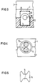
- section III-III is shown, which points to the representation of FIG. 3.
- FIG. 3 shows the cable entry area according to section III-III shown in FIG. 2 and makes it clear that the sealing block 13 fills the sealing chamber 25.
- the diameter of the cable entry opening 19 in the outer wall of the cable sleeve shell 4 is larger than the diameter of the cable entry opening 18 in the sealing block 13 in order to be able to ensure the compression of the sealing block 13.
- Figure 5 shows a filler 14 made of deformable material which can be pressed tightly within the cable entry opening.
- the filler 14 has lateral open recesses 15 in which the cables to be inserted are inserted.
- the shape of the filler 14 shown only shows the basic design; Of course, correspondingly rounded contours that are already matched to the diameter are also possible.
- FIG. 6 shows an example for the lateral connection of the cable sleeve shells 2 and 3, which have laterally projecting flanges 12. These flanges 12 are pressed together, for example, by means of screws 16 and produce the required seal via the sealing system introduced into the housing parting plane 10, which is not shown here.
- FIG. 7 shows another possibility for the mutual connection of the cable sleeve shells 2 and 3.
- the two molded flanges 12a are undercut in a wedge shape, so that a clamp 17, for example in the form of a longitudinal rail, can be slipped on as a mutual connection.
- FIG. 8 conveys a seal in a cable entry opening by means of a type of stuffing box known per se.
- the sealing material 24 used in the sealing chamber of the cable sleeve shell 3 is pressed with the aid of a compression screw 22, which has a cable insertion opening 23.
- the situation is the same as in the previous examples, in particular the formation of a second separation level for the cable entry openings, which are independent of the housing separation level.
Landscapes
- Physics & Mathematics (AREA)
- General Physics & Mathematics (AREA)
- Optics & Photonics (AREA)
- Cable Accessories (AREA)
- Installation Of Indoor Wiring (AREA)
- Details Of Indoor Wiring (AREA)
- Laying Of Electric Cables Or Lines Outside (AREA)
- Insulating Bodies (AREA)
Applications Claiming Priority (2)
| Application Number | Priority Date | Filing Date | Title |
|---|---|---|---|
| DE4138462 | 1991-11-22 | ||
| DE4138462 | 1991-11-22 |
Publications (2)
| Publication Number | Publication Date |
|---|---|
| EP0543350A1 true EP0543350A1 (fr) | 1993-05-26 |
| EP0543350B1 EP0543350B1 (fr) | 1995-09-20 |
Family
ID=6445375
Family Applications (1)
| Application Number | Title | Priority Date | Filing Date |
|---|---|---|---|
| EP92119642A Expired - Lifetime EP0543350B1 (fr) | 1991-11-22 | 1992-11-17 | Manchon de câble comprenant un boîtier divisé longitudinalement |
Country Status (10)
| Country | Link |
|---|---|
| US (1) | US5313018A (fr) |
| EP (1) | EP0543350B1 (fr) |
| JP (1) | JP3160096B2 (fr) |
| KR (1) | KR100285532B1 (fr) |
| AT (1) | ATE128282T1 (fr) |
| AU (1) | AU657812B2 (fr) |
| CA (1) | CA2083418C (fr) |
| DE (1) | DE59203753D1 (fr) |
| DK (1) | DK0543350T3 (fr) |
| ES (1) | ES2077962T3 (fr) |
Cited By (7)
| Publication number | Priority date | Publication date | Assignee | Title |
|---|---|---|---|---|
| EP0637767A2 (fr) * | 1993-07-08 | 1995-02-08 | WALTER ROSE GmbH & Co. KG | Un boîtier pour des câbles multifilaires |
| EP0660481A1 (fr) * | 1993-12-22 | 1995-06-28 | RXS Kabelgarnituren Gesellschaft mit beschränkter Haftung | Manchon de câble comprenant un boîtier fendu longitudinalement |
| EP0797114A2 (fr) * | 1996-03-20 | 1997-09-24 | RXS Kabelgarnituren Gesellschaft mit beschränkter Haftung | Boîte de jonction |
| US5775702A (en) * | 1994-03-07 | 1998-07-07 | N.V. Raychem S.A. | Sealing arrangement |
| EP0908996A1 (fr) * | 1997-10-09 | 1999-04-14 | The Furukawa Electric Co., Ltd. | Boíte pour cable optique |
| EP1261094A1 (fr) * | 2001-05-23 | 2002-11-27 | Nexans | Boítier d'appareillage, notamment boítier d'épissurage |
| WO2012007904A1 (fr) * | 2010-07-13 | 2012-01-19 | Tyco Electronics (Shanghai) Co. Ltd. | Boîtier pour épissure de fibres optiques pourvu d'un élément d'obturation élastique |
Families Citing this family (7)
| Publication number | Priority date | Publication date | Assignee | Title |
|---|---|---|---|---|
| CN1171367C (zh) * | 1997-12-09 | 2004-10-13 | Dsg-卡纳萨两合公司 | 用于保持和引导穿过细长物体的方法和装置 |
| JP2004129331A (ja) * | 2002-09-30 | 2004-04-22 | Sumitomo Rubber Ind Ltd | ケーブル配線クロージャ用端面シール部材 |
| US20120008257A1 (en) * | 2010-07-06 | 2012-01-12 | 3M Innovative Properties Company | Cell tower wiring junction box |
| WO2019103665A1 (fr) | 2017-11-22 | 2019-05-31 | Telefonaktiebolaget Lm Ericsson (Publ) | Ensemble d'étanchéité de câble |
| NL2020036B1 (nl) * | 2017-12-07 | 2019-06-19 | Leia B V | Kabelmof en werkwijze voor het aan elkaar verbinden van een eerste kabeleinde en een tweede kabeleinde |
| CN114156703A (zh) * | 2021-11-29 | 2022-03-08 | 赫兹曼电力(广东)有限公司 | 一种电力压板 |
| CN115793167B (zh) * | 2023-02-06 | 2023-06-06 | 江苏亨通光电股份有限公司 | 一种自承式蝶形皮线光缆 |
Citations (6)
| Publication number | Priority date | Publication date | Assignee | Title |
|---|---|---|---|---|
| DE941734C (de) * | 1949-12-06 | 1956-04-19 | Merten Geb | Kabelkasten aus Isolierpressstoff |
| GB1060255A (en) * | 1964-10-28 | 1967-03-01 | British Insulated Callenders | Improvements in junction boxes for electric cables |
| DE2515939A1 (de) * | 1975-04-11 | 1976-10-14 | Siemens Ag | Thermoplastklemmuffe mit dichtungskoerper |
| EP0248181A1 (fr) * | 1986-06-06 | 1987-12-09 | Audi Ag | Boîte de fusibles et de distribution pour véhicules à moteur |
| US4743209A (en) * | 1986-05-21 | 1988-05-10 | Penn Central Telecommunications Company | Compartmentalized splice case |
| FR2648630A1 (fr) * | 1989-06-20 | 1990-12-21 | Sirti Spa | Couvre-joint hermetique pour cables de telecommunication et en particulier pour cables contenant des fibres optiques |
Family Cites Families (5)
| Publication number | Priority date | Publication date | Assignee | Title |
|---|---|---|---|---|
| DE2332847A1 (de) * | 1973-06-28 | 1975-01-23 | Quante Wilhelm Spezialfab | Verbindungsmuffe fuer elektrische kabel, insbesondere nachrichtenkabel |
| US3935373A (en) * | 1975-03-04 | 1976-01-27 | Smith-Schreyer & Assoc., Inc. | Access insert for splice case |
| US4875952A (en) * | 1984-06-11 | 1989-10-24 | American Telephone And Telegraph Company, At&T Bell Laboratories | Forced encapsulation means for a cable |
| JPH0529446Y2 (fr) * | 1987-09-03 | 1993-07-28 | ||
| US5006669A (en) * | 1989-07-18 | 1991-04-09 | Siemens Aktiengesellschaft | End member for a longitudinally divided cable sleeve |
-
1992
- 1992-09-23 US US07/950,657 patent/US5313018A/en not_active Expired - Lifetime
- 1992-11-17 AT AT92119642T patent/ATE128282T1/de not_active IP Right Cessation
- 1992-11-17 ES ES92119642T patent/ES2077962T3/es not_active Expired - Lifetime
- 1992-11-17 DK DK92119642.4T patent/DK0543350T3/da active
- 1992-11-17 EP EP92119642A patent/EP0543350B1/fr not_active Expired - Lifetime
- 1992-11-17 DE DE59203753T patent/DE59203753D1/de not_active Expired - Fee Related
- 1992-11-18 JP JP30843292A patent/JP3160096B2/ja not_active Expired - Fee Related
- 1992-11-20 CA CA002083418A patent/CA2083418C/fr not_active Expired - Fee Related
- 1992-11-20 KR KR1019920021862A patent/KR100285532B1/ko not_active IP Right Cessation
- 1992-11-20 AU AU28532/92A patent/AU657812B2/en not_active Ceased
Patent Citations (6)
| Publication number | Priority date | Publication date | Assignee | Title |
|---|---|---|---|---|
| DE941734C (de) * | 1949-12-06 | 1956-04-19 | Merten Geb | Kabelkasten aus Isolierpressstoff |
| GB1060255A (en) * | 1964-10-28 | 1967-03-01 | British Insulated Callenders | Improvements in junction boxes for electric cables |
| DE2515939A1 (de) * | 1975-04-11 | 1976-10-14 | Siemens Ag | Thermoplastklemmuffe mit dichtungskoerper |
| US4743209A (en) * | 1986-05-21 | 1988-05-10 | Penn Central Telecommunications Company | Compartmentalized splice case |
| EP0248181A1 (fr) * | 1986-06-06 | 1987-12-09 | Audi Ag | Boîte de fusibles et de distribution pour véhicules à moteur |
| FR2648630A1 (fr) * | 1989-06-20 | 1990-12-21 | Sirti Spa | Couvre-joint hermetique pour cables de telecommunication et en particulier pour cables contenant des fibres optiques |
Cited By (14)
| Publication number | Priority date | Publication date | Assignee | Title |
|---|---|---|---|---|
| EP0637767A2 (fr) * | 1993-07-08 | 1995-02-08 | WALTER ROSE GmbH & Co. KG | Un boîtier pour des câbles multifilaires |
| EP0637767A3 (fr) * | 1993-07-08 | 1995-11-22 | Rose Walter Gmbh & Co Kg | Un boîtier pour des câbles multifilaires. |
| EP0660481A1 (fr) * | 1993-12-22 | 1995-06-28 | RXS Kabelgarnituren Gesellschaft mit beschränkter Haftung | Manchon de câble comprenant un boîtier fendu longitudinalement |
| US5574259A (en) * | 1993-12-22 | 1996-11-12 | Rxs Schrumpftechnik-Garnituren Gmbh | Cable sleeve composed of a longitudinally divided housing |
| US5775702A (en) * | 1994-03-07 | 1998-07-07 | N.V. Raychem S.A. | Sealing arrangement |
| EP0749641B1 (fr) * | 1994-03-07 | 1998-07-15 | N.V. Raychem S.A. | Agencement d'etancheite |
| EP0797114A3 (fr) * | 1996-03-20 | 1998-01-07 | RXS Kabelgarnituren Gesellschaft mit beschränkter Haftung | Boíte de jonction |
| EP0797114A2 (fr) * | 1996-03-20 | 1997-09-24 | RXS Kabelgarnituren Gesellschaft mit beschränkter Haftung | Boîte de jonction |
| EP0908996A1 (fr) * | 1997-10-09 | 1999-04-14 | The Furukawa Electric Co., Ltd. | Boíte pour cable optique |
| US6085013A (en) * | 1997-10-09 | 2000-07-04 | The Furukawa Electric Co., Ltd. | Optical cable closure |
| EP1261094A1 (fr) * | 2001-05-23 | 2002-11-27 | Nexans | Boítier d'appareillage, notamment boítier d'épissurage |
| FR2825199A1 (fr) * | 2001-05-23 | 2002-11-29 | Nexans | Boitier d'appareillage, notamment boitier d'epissurage |
| US6768859B2 (en) | 2001-05-23 | 2004-07-27 | Nexans | Equipment box, in particular a splice box |
| WO2012007904A1 (fr) * | 2010-07-13 | 2012-01-19 | Tyco Electronics (Shanghai) Co. Ltd. | Boîtier pour épissure de fibres optiques pourvu d'un élément d'obturation élastique |
Also Published As
| Publication number | Publication date |
|---|---|
| JP3160096B2 (ja) | 2001-04-23 |
| AU657812B2 (en) | 1995-03-23 |
| ES2077962T3 (es) | 1995-12-01 |
| ATE128282T1 (de) | 1995-10-15 |
| JPH05227638A (ja) | 1993-09-03 |
| EP0543350B1 (fr) | 1995-09-20 |
| DK0543350T3 (da) | 1996-01-08 |
| KR100285532B1 (ko) | 2001-04-02 |
| US5313018A (en) | 1994-05-17 |
| KR930011357A (ko) | 1993-06-24 |
| CA2083418C (fr) | 2002-01-29 |
| CA2083418A1 (fr) | 1993-05-23 |
| DE59203753D1 (de) | 1995-10-26 |
| AU2853292A (en) | 1993-05-27 |
Similar Documents
| Publication | Publication Date | Title |
|---|---|---|
| DE2515939C3 (de) | Thermoplastklernmuffe mit Dichtungskörper | |
| EP3517816B1 (fr) | Connecteur avec boîtier | |
| DE3512175C2 (fr) | ||
| EP0543350B1 (fr) | Manchon de câble comprenant un boîtier divisé longitudinalement | |
| DE7126050U (de) | Flussigkeitsdichter spannungsfreier Verbinder | |
| EP2492565B1 (fr) | Passage de ligne avec empilement | |
| EP0408967A2 (fr) | Corps d'étanchéité pour garnitures de câbles divisées longitudinalement | |
| EP3329566B1 (fr) | Dispositif antidéflagrant et procédé de fabrication de celui-ci | |
| EP0521324B1 (fr) | Manchon de câble | |
| DE7425454U (de) | Lippenförmiger Dichtungskörper für Kabelmuffen | |
| EP2614565B1 (fr) | Traversée de câbles | |
| DE2427677A1 (de) | Dichtungskoerper fuer kabeleinfuehrungen | |
| DE2736039B2 (de) | Aufteilungsmuffe nach dem Thermoplastklemmuffenprinzip | |
| EP1870909A1 (fr) | Câble plat | |
| EP0442367A2 (fr) | Dispositif pour boucher une ouverture de traversée de câble dans une armoire de commutation | |
| EP1503471A2 (fr) | Plaque de traversée de câble | |
| DE2050536C3 (de) | Längsgeteilte Verbindungs- und/oder Abzweigmuffe für Kabel | |
| DE102018207019A1 (de) | Wanddurchführung | |
| DE2240086C3 (de) | Elastischer Dichtungskörper für feuchtigkeitsgeschützte elektrische Installationsgeräte | |
| DE102014102260B4 (de) | Baukasten für die Abdichtung des Durchganges von Kabeln oder Adern, die durch eine Platte verlaufen sowie Verfahren zum Abdichten | |
| EP1231693A1 (fr) | Entrée de câble pour dispositif d'installation électrique | |
| DE102005011286B3 (de) | Vorrichtung zum flüssigkeits- oder gasdichten gegenseitigen Abgrenzen zweier Räume | |
| DE102013201149A1 (de) | Kabeldurchführungseinrichtung | |
| EP0638975A1 (fr) | Extrémité de manchon à pluralité d'entrées subdivisées de câbles | |
| DE10047715A1 (de) | Kabeldurchführung |
Legal Events
| Date | Code | Title | Description |
|---|---|---|---|
| PUAI | Public reference made under article 153(3) epc to a published international application that has entered the european phase |
Free format text: ORIGINAL CODE: 0009012 |
|
| AK | Designated contracting states |
Kind code of ref document: A1 Designated state(s): AT BE CH DE DK ES FR GB IT LI NL SE |
|
| 17P | Request for examination filed |
Effective date: 19930618 |
|
| 17Q | First examination report despatched |
Effective date: 19941007 |
|
| GRAA | (expected) grant |
Free format text: ORIGINAL CODE: 0009210 |
|
| AK | Designated contracting states |
Kind code of ref document: B1 Designated state(s): AT BE CH DE DK ES FR GB IT LI NL SE |
|
| REF | Corresponds to: |
Ref document number: 128282 Country of ref document: AT Date of ref document: 19951015 Kind code of ref document: T |
|
| REF | Corresponds to: |
Ref document number: 59203753 Country of ref document: DE Date of ref document: 19951026 |
|
| REG | Reference to a national code |
Ref country code: ES Ref legal event code: FG2A Ref document number: 2077962 Country of ref document: ES Kind code of ref document: T3 |
|
| ITF | It: translation for a ep patent filed |
Owner name: STUDIO JAUMANN |
|
| GBT | Gb: translation of ep patent filed (gb section 77(6)(a)/1977) |
Effective date: 19951127 |
|
| REG | Reference to a national code |
Ref country code: DK Ref legal event code: T3 |
|
| ET | Fr: translation filed | ||
| PLBE | No opposition filed within time limit |
Free format text: ORIGINAL CODE: 0009261 |
|
| STAA | Information on the status of an ep patent application or granted ep patent |
Free format text: STATUS: NO OPPOSITION FILED WITHIN TIME LIMIT |
|
| 26N | No opposition filed | ||
| PGFP | Annual fee paid to national office [announced via postgrant information from national office to epo] |
Ref country code: AT Payment date: 20001103 Year of fee payment: 9 Ref country code: CH Payment date: 20001103 Year of fee payment: 9 Ref country code: DK Payment date: 20001103 Year of fee payment: 9 Ref country code: NL Payment date: 20001103 Year of fee payment: 9 |
|
| PGFP | Annual fee paid to national office [announced via postgrant information from national office to epo] |
Ref country code: SE Payment date: 20011101 Year of fee payment: 10 |
|
| PG25 | Lapsed in a contracting state [announced via postgrant information from national office to epo] |
Ref country code: AT Free format text: LAPSE BECAUSE OF NON-PAYMENT OF DUE FEES Effective date: 20011117 Ref country code: DK Free format text: LAPSE BECAUSE OF NON-PAYMENT OF DUE FEES Effective date: 20011117 |
|
| PG25 | Lapsed in a contracting state [announced via postgrant information from national office to epo] |
Ref country code: LI Free format text: LAPSE BECAUSE OF NON-PAYMENT OF DUE FEES Effective date: 20011130 Ref country code: CH Free format text: LAPSE BECAUSE OF NON-PAYMENT OF DUE FEES Effective date: 20011130 |
|
| REG | Reference to a national code |
Ref country code: GB Ref legal event code: IF02 |
|
| PG25 | Lapsed in a contracting state [announced via postgrant information from national office to epo] |
Ref country code: NL Free format text: LAPSE BECAUSE OF NON-PAYMENT OF DUE FEES Effective date: 20020601 |
|
| REG | Reference to a national code |
Ref country code: CH Ref legal event code: PL |
|
| REG | Reference to a national code |
Ref country code: DK Ref legal event code: EBP |
|
| NLV4 | Nl: lapsed or anulled due to non-payment of the annual fee |
Effective date: 20020601 |
|
| PG25 | Lapsed in a contracting state [announced via postgrant information from national office to epo] |
Ref country code: SE Free format text: LAPSE BECAUSE OF NON-PAYMENT OF DUE FEES Effective date: 20021118 |
|
| EUG | Se: european patent has lapsed | ||
| BECA | Be: change of holder's address |
Owner name: *CCS TECHNOLOGY INC.103 FOULK ROAD, WILMINGTON, DE Effective date: 20040119 |
|
| BECH | Be: change of holder |
Owner name: *CCS TECHNOLOGY INC. Effective date: 20040119 |
|
| BECN | Be: change of holder's name |
Owner name: *CCS TECHNOLOGY INC. Effective date: 20040119 |
|
| REG | Reference to a national code |
Ref country code: GB Ref legal event code: 732E |
|
| REG | Reference to a national code |
Ref country code: ES Ref legal event code: PC2A |
|
| REG | Reference to a national code |
Ref country code: FR Ref legal event code: TP Ref country code: FR Ref legal event code: CD |
|
| PG25 | Lapsed in a contracting state [announced via postgrant information from national office to epo] |
Ref country code: IT Free format text: LAPSE BECAUSE OF NON-PAYMENT OF DUE FEES;WARNING: LAPSES OF ITALIAN PATENTS WITH EFFECTIVE DATE BEFORE 2007 MAY HAVE OCCURRED AT ANY TIME BEFORE 2007. THE CORRECT EFFECTIVE DATE MAY BE DIFFERENT FROM THE ONE RECORDED. Effective date: 20051117 |
|
| PGFP | Annual fee paid to national office [announced via postgrant information from national office to epo] |
Ref country code: DE Payment date: 20081223 Year of fee payment: 17 |
|
| PGFP | Annual fee paid to national office [announced via postgrant information from national office to epo] |
Ref country code: ES Payment date: 20091126 Year of fee payment: 18 |
|
| PGFP | Annual fee paid to national office [announced via postgrant information from national office to epo] |
Ref country code: FR Payment date: 20091201 Year of fee payment: 18 Ref country code: GB Payment date: 20091125 Year of fee payment: 18 |
|
| PGFP | Annual fee paid to national office [announced via postgrant information from national office to epo] |
Ref country code: BE Payment date: 20091224 Year of fee payment: 18 |
|
| PG25 | Lapsed in a contracting state [announced via postgrant information from national office to epo] |
Ref country code: DE Free format text: LAPSE BECAUSE OF NON-PAYMENT OF DUE FEES Effective date: 20100601 |
|
| BERE | Be: lapsed |
Owner name: *CCS TECHNOLOGY INC. Effective date: 20101130 |
|
| GBPC | Gb: european patent ceased through non-payment of renewal fee |
Effective date: 20101117 |
|
| REG | Reference to a national code |
Ref country code: FR Ref legal event code: ST Effective date: 20110801 |
|
| PG25 | Lapsed in a contracting state [announced via postgrant information from national office to epo] |
Ref country code: BE Free format text: LAPSE BECAUSE OF NON-PAYMENT OF DUE FEES Effective date: 20101130 |
|
| PG25 | Lapsed in a contracting state [announced via postgrant information from national office to epo] |
Ref country code: FR Free format text: LAPSE BECAUSE OF NON-PAYMENT OF DUE FEES Effective date: 20101130 |
|
| PG25 | Lapsed in a contracting state [announced via postgrant information from national office to epo] |
Ref country code: GB Free format text: LAPSE BECAUSE OF NON-PAYMENT OF DUE FEES Effective date: 20101117 |
|
| REG | Reference to a national code |
Ref country code: ES Ref legal event code: FD2A Effective date: 20120110 |
|
| PG25 | Lapsed in a contracting state [announced via postgrant information from national office to epo] |
Ref country code: ES Free format text: LAPSE BECAUSE OF NON-PAYMENT OF DUE FEES Effective date: 20101118 |