EP2614565B1 - Traversée de câbles - Google Patents
Traversée de câbles Download PDFInfo
- Publication number
- EP2614565B1 EP2614565B1 EP11761276.2A EP11761276A EP2614565B1 EP 2614565 B1 EP2614565 B1 EP 2614565B1 EP 11761276 A EP11761276 A EP 11761276A EP 2614565 B1 EP2614565 B1 EP 2614565B1
- Authority
- EP
- European Patent Office
- Prior art keywords
- sealing element
- sealing
- pressure
- cable bushing
- housing
- Prior art date
- Legal status (The legal status is an assumption and is not a legal conclusion. Google has not performed a legal analysis and makes no representation as to the accuracy of the status listed.)
- Not-in-force
Links
Images


Classifications
-
- H—ELECTRICITY
- H02—GENERATION; CONVERSION OR DISTRIBUTION OF ELECTRIC POWER
- H02G—INSTALLATION OF ELECTRIC CABLES OR LINES, OR OF COMBINED OPTICAL AND ELECTRIC CABLES OR LINES
- H02G3/00—Installations of electric cables or lines or protective tubing therefor in or on buildings, equivalent structures or vehicles
- H02G3/22—Installations of cables or lines through walls, floors or ceilings, e.g. into buildings
-
- F—MECHANICAL ENGINEERING; LIGHTING; HEATING; WEAPONS; BLASTING
- F16—ENGINEERING ELEMENTS AND UNITS; GENERAL MEASURES FOR PRODUCING AND MAINTAINING EFFECTIVE FUNCTIONING OF MACHINES OR INSTALLATIONS; THERMAL INSULATION IN GENERAL
- F16L—PIPES; JOINTS OR FITTINGS FOR PIPES; SUPPORTS FOR PIPES, CABLES OR PROTECTIVE TUBING; MEANS FOR THERMAL INSULATION IN GENERAL
- F16L5/00—Devices for use where pipes, cables or protective tubing pass through walls or partitions
- F16L5/02—Sealing
- F16L5/10—Sealing by using sealing rings or sleeves only
-
- H—ELECTRICITY
- H02—GENERATION; CONVERSION OR DISTRIBUTION OF ELECTRIC POWER
- H02G—INSTALLATION OF ELECTRIC CABLES OR LINES, OR OF COMBINED OPTICAL AND ELECTRIC CABLES OR LINES
- H02G15/00—Cable fittings
- H02G15/013—Sealing means for cable inlets
Definitions
- the invention relates to a cable bushing, in particular for a motor vehicle for the sealed guidance of a cable harness with a plurality of electrical lines through a wall opening with the features of the preamble of claim 1.
- Such a cable bushing can be seen for example from the US 2007/0193766 A1 ,
- the sealing system comprises a receiving body made of a resilient material, which is compressed by two shell segments, which act in the applied state as a clamping frame, in order to achieve a moisture-proof application of the receiving body to the lines.
- the receiving body consists of a dimensionally stable elastic block of rubber or rubber-like material. In this block through holes are provided for the lines. Slots from the through holes lead to the outside of the receiving body. As a result, the receiving body for inserting the lines can be opened a little.
- From the DE 697 14 720 T2 is to take a seal for an opening closure, in which a sealing element between the pressure plates is arranged and the lines are individually guided by the pressure plates and the sealing element.
- WO 01/81807 A1 From the WO 01/81807 A1 is a device for the sealed implementation of, for example, pipes to be taken through wall openings. Between the pipe and an introduced into the wall opening wall sleeve is a introduced annular sealing element, which is penetrated in the axial direction of screws, which clamp the sealing element in the axial direction, so that it is spread in the radial direction.
- a sealing insert for cable bushings which has a plurality of passage openings for individual strands, which are each open to the outer periphery of the sealing element via a running in raidaler direction insertion slot to the outside, so that the individual strands inserted from the peripheral side into the bushings can be.
- the invention has for its object to provide an improved with regard to the longitudinal water-tightness cable entry.
- a grommet in particular for a motor vehicle, for sealingly guiding a cable harness with a plurality of electrical lines through a wall opening, comprising a dimensionally stable housing for insertion into the wall opening, which encloses a sealing element formed as a prefabricated unit of an elastic sealing material, wherein recordings for the individual guidance of the electroluminescent lines in an axial direction are provided in the sealing element. Furthermore, a pressure element is provided, which exerts a compressive force on the sealing element such that the sealing material alsweltet in the radial direction perpendicular to the axial direction, that is displaced radially outward.
- the electrical lines are individually tightly enclosed by the sealing material and preferably at the same time the sealing element is pressed radially against the housing.
- the pressure element on pins which protrude into holes in the sealing element in such a way that on the pins a radial compressive force is exerted on the sealing material of the sealing element in the region of the holes, which at least supports the radial pressing of the sealing element against the housing.
- the pins have an excess of the holes, so a larger diameter, whereby a seal of the pins is ensured in the sealing element is.
- the pins of the printing element are e.g. the axial fixation of the sealing element, in particular, the two parts of the sealing element can be connected to one another via the pins.
- the pins In addition to the function of radial expansion, the pins also serve for precise (rotational) positioning of the pressure elements with respect to the sealing element and have advantages during assembly.
- the pins extend in the axial direction.
- two pressure plates are provided as pressure elements which enclose the sealing element between them.
- Each pressure plate preferably has pins which project into the sealing element.
- the pins of the opposing pressure plates are aligned with one another.
- the pins extend respectively only a portion in the sealing element inside.
- the printing plates are not connected to each other.
- the pins extend in a plane perpendicular to the axial plane.
- the pressure elements are designed as brackets which extend around the circumference of the pressure element, so that a plurality of pins are inserted from several sides into the pressure element.
- This embodiment can alternatively or in addition to the printing plates, the front side exert a compressive force on the pressure element.
- the housing has a peripheral surface which is provided with openings for the pins and the brackets are on the outside of the housing on the peripheral surface. Due to the fact that the stirrups, i. the pressure element is arranged outside the housing, the radial expansion of the sealing element is limited only by the housing, so that a good seal between the sealing element and the housing is formed. This eliminates the need to seal the bracket relative to the housing.
- the housing in this case has a mounting flange with a contact surface for engagement with an edge of the opening and a peripheral seal, which is in particular an O-ring, for sealing the housing to the wall opening out.
- the dimensionally stable housing usually designed as a dimensionally stable plastic injection-molded part, not only serves to seal the cable gland against the wall opening. Rather, it is also used to support the pressure element, wherein the housing in particular forms an abutment, so that the pressure element can exert its pressure force on the prefabricated, in particular cylindrical sealing element of the resilient sealing material.
- the compressive force in this case causes a widening of the sealing material of the Dichtelemerits, so that the sealing element is pressed in the radial direction against the housing and also the sealing material, the individual electrical plinsgen tightly encloses.
- the sealing of the cable harness is based on a defined expansion of the elastic sealing material by which not only a secure seal around the electrical lines is created, but also in the contact area between the sealing element and the housing can not penetrate water. In a cable bushing constructed in this way, it is therefore sufficient to merely insert the cable feedthrough into the wall opening and seal it via the O-ring in relation to the wall opening.
- the cable bushing is therefore a prefabricated unit, which together with the cables in particular form a prefabricated cable set, in which, for example, the end of the lines already plugs are struck.
- the individual components of the grommet such as sealing element, pressure element, housing, are also prefabricated, separate individual units, which are in particular detachably connected to each other, so that a repair and replacement of defective components or lines is possible. Potting a sealant in the housing to form the sealing element is therefore not provided.
- the sealing material of the sealing element is preferably rubber-elastic overall and, for example, a (moss) rubber, a (thermoplastic) elastomer or a (silicone) rubber.
- the sealing element preferably has at least one separation point which extends over the entire length of the sealing element, such that the individual electrical leads are laterally and at least approximately perpendicular to the axial direction via the separation point can be introduced in the radial direction in the sealing element.
- a passage through the individual electrical lines is not required, but the lines are inserted into the receptacles via the at least one separation point, which extends between the two end faces of the sealing element.
- the introduction of the electrical leads is thus perpendicular, ie laterally to the axial direction and not in the axial direction as in the insertion of the electrical lines. In case of a possible defect of components of the cable gland, it can be dismantled non-destructively for repair purposes.
- the pressure element on two opposite parts, which are in particular positively connected with each other.
- the pressure element acts e.g. on both end faces of the sealing element.
- both parts of the pressure element extend around the circumference of the sealing element.
- the parts of the pressure element are preferably positively and releasably connected to each other, e.g. via a latching or snap connection. In the case of disassembly of the cable gland, the pressure element can thus be quickly disassembled.
- the slots are formed as slots around the circumference of the sealing element and extend from there to the shots.
- the slots are preferably formed only as cuts without an open slot width, so that the edge sides of the slots lie directly against each other.
- the electrical wires are pressed from the outside of the sealing element into the receptacles.
- a good seal of the slots is achieved by the slots preferably extend obliquely outwardly with respect to a radial and in particular have a curved course. As a result, the slots are reliably closed tightly as soon as a resultant radial force is exerted on the pressure element, which leads to the radial expansion of the sealing material.
- the pressure element comprises two pressure plates, which abut end face on the sealing element.
- the printing plates exert a large-scale pressure force on the end face of the printing element, whereby the printing element widens in the radial direction.
- the pressure element or the sealing element on at least one pressure surface portion which is oriented obliquely to the axial direction such that thereby by the axial compression the sealing element creates a radially outwardly acting force component. In terms of design, this is achieved, for example, in that the pressure element is convex.
- the end faces of the sealing element are in particular made concave.
- An increased surface pressure on the housing by the radially expanded sealing element is achieved by preferably the sealing element has a profiling on the circumferential side, by which the lateral surface of the sealing element is reduced.
- the profiling is e.g. formed in the manner of one or more extending around the circumference of the sealing element grooves.
- the pressure plates act as large as possible on the pressure element, their diameter is about as large as that of the sealing element.
- the pressure plates have according to a preferred embodiment, circumferential recesses for the electrical lines, the recesses are designed in particular for engaging behind and captive receiving the lines and, for example, L-shaped. After inserting the electrical leads in the L-shaped recesses, the pressure plates are slightly twisted in particular in opposite directions, thereby falling out of the electrical wires is prevented.
- the housing advantageously has a stop whose diameter is smaller than the diameter of the pressure plates.
- an axial abutment is required, especially if the two pressure plates are not connected to each other, which is attached to the housing, for example, after mounting the pressure plates in the housing.
- an annular locking element is preferably provided, which is in particular positively and detachably connectable to the housing and thereby exerts an axial force on the Druckelemerit or one of the printing plates. The connection takes place here in particular in the manner of a bayonet closure. The locking element thus forms a second axial stop for one of the printing plates.
- the locking element is connected in a vördefined position with the housing, whereby the relative position between the housing and the locking element is locked in the axial direction, so that a predefined contact force in the axial direction acts on the applied pressure plate.
- the locking element is, for example, a locking ring with a narrowed neck whose diameter is smaller than the diameter of the printing plates. Particularly advantageous when using the locking element is that no other components, such as screws, washers or threaded inserts are needed.
- the connection between the locking element and the housing takes place in particular via a bayonet lock.
- snap-in hooks for example, are provided on the locking latch, which snap into place on the housing. The compression of the sealing element on the sealing plates is determined by the constructive length of the snap hooks.
- the separation point is formed according to a further preferred variant by at least one parting plane and the sealing element consists of two or more adjacent sealing bodies, wherein at least in a sealing body channels are provided which in the assembled state of the sealing element, the receptacles for the electrical lines form.
- the juxtaposed channels each extend in the axial direction and lie in the parting plane. This is therefore spanned by the channels.
- the channels are radially open, so that the electrical lines are inserted into the channels without much effort. Only when joining the two or more sealing bodies, the channels are closed, whereby the receptacles for the electrical lines are formed.
- the assembly of the electrical lines is simplified by the channels are advantageously designed for captive receiving the lines and this considered in cross-section each having an undercut, so that the individual lines are partially encompassed by the sealing material.
- the already inserted in the channels lines are thus held captive in position as long as further lines are pressed into the channels provided for them.
- a particularly efficient sealing of the electrical lines in the receptacles along their length is achieved if the channels preferably have a constriction in a section. At the site of the constriction a particularly high surface pressure is achieved to seal the pipes.
- the constriction may also be formed as a web extending transversely to the axial direction, which completely blocks the channels. When inserting the lines in the channels, the elastic sealing material is pushed away in the region of the web.
- At least one bead-like thickening is formed around the circumference of the sealing element, in particular in the region of the bores, which is compressed in the assembled state of the cable feedthrough. This is preferably also provided in the variant with the front side arranged printing plates.
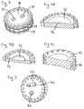
- FIG Figures 1 and 2 A first embodiment variant of a cable feedthrough 2 for the sealed guidance of a cable harness through a wall opening is shown in FIG Figures 1 and 2 shown.
- the cable harness comprises a plurality of electrical lines 4 of a cable harness 5 (see Fig. 7 ), for reasons of clarity in Fig. 1 and 2 only one is shown, which is identified by the reference numeral 4.
- a protective cap 7 is provided to protect the electrical cable line 4 outside the cable gland 2.
- the cable bushing 2 comprises a dimensionally stable housing 6 for insertion into the wall opening.
- an O-ring 8 is provided to seal the housing 6 with respect to the wall opening.
- the housing 6 has a flange-like stop for abutment against an edge of the wall opening.
- the grommet 2 also includes a sealing member 16, which in this embodiment is a one-piece, solid cylindrical body made of an elastic sealing material such as rubber.
- a plurality of slits 18 extending in the axial direction A are formed around the circumference of the sealing element 16 and extend in each case as far as a cylindrical receptacle 20 for the individual guidance of the electrical leads 4 in the axial direction A.
- the receptacles 20 accordingly form a concentric circle not far from the lateral surface of the sealing element 16. Viewed in cross-section, the slots 18 have a curved course.
- the electrical leads 4 are in this case pressed through the slots 18 perpendicular to the axial direction A up to the receptacles 20 ..
- a pressure plate 22 At both end faces of the sealing element 16 is in each case a pressure plate 22, wherein the pressure plates 22 are part of a two-part pressure element 24, by means of which a compressive force is exerted on the sealing element 16.
- the pressure force on the pressure element 24 by a Ver locking element 26 is generated, which is fixedly connected via a bayonet lock with the housing 6.
- the locking element 26 and the pressure plates 22 are solid and dimensionally stable components.
- the pressure plates 22 have around their circumference a plurality of recesses 27 through which the electrical leads are guided.
- the number of recesses corresponds to the number of receptacles 20 in the sealing element 16.
- the recesses 27 are viewed in cross-section preferably L-shaped, so that falling out of the electrical lines 4 during assembly is prevented (see. Fig. 4A, 4B ). For this purpose, the pressure plates 22 are rotated against each other.
- the pressure plates 22 preferably have pins 42, as for example in Fig. 5 is shown.
- each pressure plate 22 has a plurality of Stif th, for example, two, three or more pins. These penetrate preferably on both sides in each case a common bore 41 (see. Fig. 3 ) of the sealing element 16 a.
- the pins 42 have a larger diameter than the associated bore 41, so that the sealing material displaced in the radial direction and thereby improved longitudinal water-tightness is achieved.
- the sealing element 16 may have around its periphery a profiling in the manner of one or more grooves 29 (see. Fig. 3 ).
- Fig. 1 the end faces of the sealing element 16 on a flat course in a transverse plane, which is transverse to the axial direction A. Also, the sides of the pressure plates 22 which abut the sealing element 16 are formed flat. However, it is possible to generate a radial force component of the compressive force on the sealing element 16 by a pressure surface portion 32 of the pressure plates 22 or the end face of the sealing element 16 inclined to the axial direction A, for example, are convex. Examples are in the FIGS. 4A, 4B, 4C shown. In addition, if the pressure surface portion 32 of the pressure plates 22 is convex, the end faces of the sealing element 16 may be concave. The convex pressure surface portion 32 is formed, for example, in the manner of a central elevation of the end face, but it may also extend in an annular manner on the end face.
- the locking element 26 has a constricted neck 28 whose diameter is smaller than that of the pressure plates 22.
- the neck 28 forms an axial stop for one of the pressure plates 22.
- a further stop 30 is formed for the second pressure plate 22, so that the position of the second pressure plate 22 is fixed in the housing 6.
- the diameter of the stopper 30 is smaller than a diameter of the pressure plates 22.
- the locking element 26 can be connected to the housing 6 via snap hooks which engage on the housing 6.
- the pressure force depends in particular on the length of Schnäpphakens.
- the pressure plates 22 each have - as in Fig. 5 shown - preferably axially extending pins 42 which through axial bores 41 in the sealing element 16 (see Fig. 3 ) are performed.
- only one of the pressure plates 22 has axial pins which are about as long as the sealing element 16 is wide in the axial direction A, and the other pressure plate has receptacles, eg detent recesses 43 for the end of the pins.
- This embodiment is used in addition to the compression of the sealing element 16 as an assembly aid in the in Fig. 5 illustrated variant, each of the pressure plates 22, a pin 42 and a locking receptacle 43.
- the second embodiment of the cable gland 2 according to FIGS. 6 to 8 differs from the first in that the pressure element 24, consists of two brackets 34 which are arranged around the sealing element 16.
- the sealing element 16 is divided into two parallel parting planes, so that the sealing element 16 consists of three sealing bodies 36a, 36b and 36c.
- channels 38 are formed, which extend in the axial direction A over the entire length of the sealing body 36 a, 36 b, 36 c.
- the channels 38 are radially open, so that in this the electrical lines 4 can be inserted.
- the channels 38 on a middle sealing body 36b also have undercuts 39, which in Fig. 9 are shown.
- the electrical lines 4 when they are inserted in the channels 38, the sealing material behind grasped. This prevents that during the installation of the cable gland 2, the lines 4 guided along the middle sealing body 36b and in particular the lines 4 fall out on the lower side of the middle sealing body 36b.
- the two outer sealing bodies 36a, 36c have, in a partial section, a constriction 40 of the channels 38, by means of which the electrical lines 4 are axially fixed in the assembled state.
- the lines 4 in the receptacles 20, through the channels 38 on the middle sealing body 36b and through the corresponding channels 38 on the outer sealing bodies 36a, 36c in the interior of the sealing element 16th are formed, individually enclosed by the sealing material. Since the sealing body 16 has two part levels, the lines 4 of the cable strand 5 are divided into two mutually parallel planes. In the case of a sealing element 16 which is composed of more than three sealing bodies 36a, 36b, 36c, the number of planes of lines 4 is correspondingly greater.
- pins 42 are used in the second embodiment, which protrude inwardly from the brackets 34 and extend perpendicular to the axial direction A.
- bores 44 are provided in the sealing bodies 36a, 36b, 36c, the pins 42 having an oversize relative to the bores 44, so that the pins 42 exert a compressive force on the sealing element 16 when inserted into the bores 44 , By this pressure force, the sealing element 16 can expand both axially and radially, so that it is pressed against the housing 6.
- the two brackets 34 of the pressure element 24 are not attached directly to the sealing element 16, but they abut against a peripheral surface 46 of the housing 6.
- the peripheral surface 46 of the housing 6 is provided for this purpose with openings 48 for the pins 42.
- the bracket 34 are releasably connected together to form the pressure element 24.
- the connection is in particular positive and takes place via a latching nose 52, which engages in a latching receptacle 54 of the respective other bracket 34.
- the sealing element 16 has around its circumference a plurality of bead-like thickenings 50. If the sealing element 16 is enclosed by the housing 6 and the pins 42 are inserted into the bores 44, the sealing element 16 lies in the region of the thickenings 50 particularly close to the housing 6.
- Both described embodiments of a cable gland 2 are characterized in that a particularly good sealing of the cable gland 2 is achieved by the elastic sealing element 16 is radially expanded and thereby pressed against the housing 6.
- the difference between the two embodiments lies essentially in the fact that in the first the pressure element 24, through which the pressure force is introduced into the sealing element 16, acts axially on the end faces of the sealing element 16 and in the second embodiment, the pressure force on the pins 42 ins Interior of the sealing element 16 is initiated. Due to the different arrangement of the pressure element 24 with respect to the sealing element 16 and the sealing element 16 is designed differently in the two embodiments. In the first embodiment, it has around its circumference axially extending separation points, which are formed as slots 18 to reach the receptacles 20 for the lines 4. In the second embodiment, the separation points are formed by two parting lines, so that the sealing element 16 is designed in three parts.
- the lines 4 can be inserted in a simple manner perpendicular to the axial direction A in the receptacles 20.
- the cable guides 2 can be dismantled quickly and easily in case of failure.
- LIST OF REFERENCE NUMBERS 30 attack 2 Grommet 32
- Pressure surface section 4 electrical line 34 hanger 5 wire harness 36a, b, c sealing body 6 casing 38 channel 7 protective cap 39 undercut 8th O-ring 40 narrowing 10 screw 41 drilling 12 Rifle 42 pen 14 eyelet 43 latching receptacle 16 sealing element 44 drilling 18 slot 46 peripheral surface 20 admission 48 opening 22 printing plate 50 thickening 24 pressure element 52 locking lug 26 locking element 54 latching receptacle 27 recesses 28 neck A axially 29 groove
Landscapes
- Engineering & Computer Science (AREA)
- Architecture (AREA)
- Civil Engineering (AREA)
- Structural Engineering (AREA)
- General Engineering & Computer Science (AREA)
- Mechanical Engineering (AREA)
- Installation Of Indoor Wiring (AREA)
- Motor Or Generator Frames (AREA)
Claims (15)
- Traversée de câbles (2), notamment destiné à un véhicule automobile, pour le guidage étanche d'un faisceau de câbles (5) avec plusieurs conducteurs électriques (4) à travers une ouverture de paroi, comprenant un boitier (6) de forme rigide destiné à être inséré dans l'ouverture de paroi et entourant un élément d'étanchéité (16) en un matériau d'étanchéité élastique, des logements d'accueil (20) étant prévus dans une direction axiale (A) dans l'élément d'étanchéité (16), pour le guidage individuel des conducteurs électriques (4), l'ensemble comprenant également un élément de compression (24), qui exerce une force de compression sur l'élément d'étanchéité (16) de manière telle que le matériau d'étanchéité soit refoulé ou repoussé radialement vers l'extérieur,
caractérisée en ce que l'élément d'étanchéité (16) présente des alésages (41, 44), et l'élément de compression (24) présente des broches (42) qui s'engagent dans les alésages (41, 44), les broches (42) présentant une surcote dimensionnelle par rapport aux alésages (41, 44) et conduisant à un refoulement radial du matériau d'étanchéité de l'élément d'étanchéité (16). - Traversée de câbles (2) selon la revendication 1, dans laquelle les alésages et les broches (2) s'étendent dans la direction axiale (A) ou perpendiculairement à la direction axiale (A).
- Traversée de câbles (2) selon la revendication 2, caractérisée en ce que l'élément de compression (24) comprend deux étriers (34), qui entourent l'élément d'étanchéité (16) sur sa périphérie.
- Traversée de câbles (2) selon la revendication 3, dans laquelle le boitier (6) présente une surface périphérique (46), qui est pourvue d'ouvertures (48), et les étriers (34) s'appuient contre la surface périphérique (46).
- Traversée de câbles (2) selon l'une des revendications précédentes, dans laquelle l'élément d'étanchéité (16) présente au moins une zone de séparation ou de sectionnement, qui s'étend sur toute la longueur de l'élément d'étanchéité (16), de sorte que les conducteurs électriques (4) individuels peuvent être déposés dans l'élément d'étanchéité (16) par l'intermédiaire de la zone de séparation ou de sectionnement, perpendiculairement à la direction axiale.
- Traversée de câbles (2) selon l'une des revendications précédentes, dans laquelle l'élément de compression (24) comprend deux parties (22, 34) mutuellement opposées.
- Traversée de câbles (2) selon la revendication 5 et l'une des revendications précédentes, dans laquelle sont prévues plusieurs zones de séparation ou de sectionnement, qui sont réalisées sous forme de fentes (18), et s'étendent de la périphérie de l'élément d'étanchéité (16) jusqu'aux logements d'accueil (20).
- Traversée de câbles (2) selon l'une des revendications précédentes, dans laquelle sélectivement ou en combinaison, l'élément de compression (24) ou l'élément d'étanchéité (16) présente un tronçon de surface de compression (32), qui est orienté de manière inclinée par rapport à la direction axiale (A) de façon telle que lors de l'écrasement axial ou de la compression axiale de l'élément d'étanchéité (16), il apparaisse une composante de force agissant radialement vers l'extérieur.
- Traversée de câbles (2) selon l'une des revendications précédentes, dans laquelle l'élément d'étanchéité (16) présente un profilage (29) sur le côté périphérique.
- Traversée de câbles (2) selon l'une des revendications précédentes, dans laquelle l'élément de compression (24) comprend des plaques de compression (22), qui présentent, sur la périphérie, des évidements (27) pour les conducteurs électriques (4), notamment conçus pour accueillir en contre-dépouille les conducteurs (4), et dans laquelle le boitier (6) comporte une butée (30) dont le diamètre est plus petit qu'un diamètre des plaques de compression (22).
- Traversée de câbles (2) selon l'une des revendications précédentes, dans laquelle il est prévu un élément de verrouillage (26), qui peut être relié, notamment par complémentarité de formes, avec le boitier (6), en exerçant ainsi une force de compression axiale sur l'élément de compression (24), et dans laquelle une position relative entre le boitier (6) et l'anneau de verrouillage (26) est fixée dans la direction axiale (A).
- Traversée de câbles (2) selon l'une des revendications précédentes, dans laquelle la zone de séparation ou de sectionnement est formée par au moins un plan de séparation ou de sectionnement s'étendant dans la direction axiale (A), et l'élément d'étanchéité (16) est constitué de deux ou plusieurs corps d'étanchéité (36a, 36b, 36c) adjacents, des canaux (38) étant prévus dans au moins un des corps d'étanchéité (36a, 36b, 36c) et formant, dans l'état assemblé de l'élément d'étanchéité (16), les logements d'accueil (20) pour les conducteurs électriques (4).
- Traversée de câbles (2) selon la revendication 12, dans laquelle les canaux (38), vus en section transversale, présentent chacun une contre-dépouille (39), de sorte que les conducteurs individuels (4) sont enserrés partiellement par le matériau d'étanchéité.
- Traversée de câbles (2) selon la revendication 12 ou la revendication 13, dans laquelle les canaux (38) présentent, sur un tronçon partiel, un rétrécissement (40).
- Traversée de câbles (2) selon l'une des revendications précédentes, dans laquelle autour de la périphérie de l'élément d'étanchéité (16), notamment dans la zone des alésages (44), est formé au moins un renflement (50) en forme de bourrelet.
Applications Claiming Priority (2)
| Application Number | Priority Date | Filing Date | Title |
|---|---|---|---|
| DE201010045146 DE102010045146A1 (de) | 2010-09-11 | 2010-09-11 | Kabeldurchführung |
| PCT/EP2011/004243 WO2012031690A2 (fr) | 2010-09-11 | 2011-08-24 | Traversée de câbles |
Publications (2)
| Publication Number | Publication Date |
|---|---|
| EP2614565A2 EP2614565A2 (fr) | 2013-07-17 |
| EP2614565B1 true EP2614565B1 (fr) | 2016-08-03 |
Family
ID=44681062
Family Applications (1)
| Application Number | Title | Priority Date | Filing Date |
|---|---|---|---|
| EP11761276.2A Not-in-force EP2614565B1 (fr) | 2010-09-11 | 2011-08-24 | Traversée de câbles |
Country Status (4)
| Country | Link |
|---|---|
| US (1) | US9006589B2 (fr) |
| EP (1) | EP2614565B1 (fr) |
| DE (1) | DE102010045146A1 (fr) |
| WO (1) | WO2012031690A2 (fr) |
Families Citing this family (5)
| Publication number | Priority date | Publication date | Assignee | Title |
|---|---|---|---|---|
| EP2863505A4 (fr) * | 2012-06-15 | 2016-02-17 | Martins Neto João | Presse-câble à indicateur de serrage |
| US10557573B2 (en) * | 2016-11-04 | 2020-02-11 | United Technologies Corporation | Feed through seals and fittings |
| DE102020104086A1 (de) | 2020-02-17 | 2021-08-19 | Alstom Transport Technologies | Kabelhaltevorrichtung, entsprechende Montagegruppe und Fahrzeug |
| CN115013741B (zh) * | 2022-08-09 | 2022-10-18 | 河北巨擎管道制造有限公司 | 一种具有节能监测功能的预制直埋保温管及其监测方法 |
| SE2251185A1 (en) * | 2022-10-10 | 2024-04-11 | Roxtec Ab | A transit system and method for retaining cables |
Family Cites Families (17)
| Publication number | Priority date | Publication date | Assignee | Title |
|---|---|---|---|---|
| US4267401A (en) * | 1978-07-03 | 1981-05-12 | Wilkinson William L | Seal plug |
| JPS5839216A (ja) * | 1981-08-31 | 1983-03-07 | アイシン・エィ・ダブリュ株式会社 | 油圧機器における電線の連結封止方法および装置 |
| US4622436A (en) * | 1985-05-21 | 1986-11-11 | L & F Company | Plug assembly and method for encapsulating a cable within a conduit |
| DE3544785A1 (de) | 1985-12-18 | 1987-06-19 | Bayerische Motoren Werke Ag | Abdichtungssystem fuer leitungen |
| DE3828693C1 (fr) | 1988-08-24 | 1989-10-26 | Plastoform Gmbh & Co Kg, 4973 Vlotho, De | |
| JP2766558B2 (ja) * | 1991-02-14 | 1998-06-18 | 矢崎総業株式会社 | 油洩れ防止用電線保持ケース |
| US5235138A (en) * | 1991-06-24 | 1993-08-10 | Shah Jagdish H | Penetration plug for pressure vessels |
| JP2823037B2 (ja) * | 1993-11-11 | 1998-11-11 | 矢崎総業株式会社 | 電線保持ケース |
| PE69897A1 (es) | 1996-05-02 | 1997-11-05 | Raychem Sa Nv | Cierre para sellar una abertura |
| DE29803091U1 (de) * | 1998-02-25 | 1998-04-30 | Doyma Gmbh & Co | Vorrichtung zur dichten Durchführung mindestens eines Kabels und/oder Rohres o.dgl. durch einen in einer Wand ausgebildeten Durchbruch |
| GB0003073D0 (en) * | 2000-02-11 | 2000-03-29 | Raychem Sa Nv | Wraparound sealing cable termination |
| DE10020493A1 (de) * | 2000-04-26 | 2001-11-08 | Dsi Rohrleitungsbau Zubehoer | Vorrichtung zum Abdichten eines von einem inneren und einem äußeren Körper begrenzten Ringraumes |
| DE10162813A1 (de) * | 2001-12-19 | 2003-07-10 | Manfred Schmitt | Durchführungsdichtung |
| EP1565776A1 (fr) * | 2002-11-30 | 2005-08-24 | Tyco Electronics UK Limited | Dispositif d'etancheification |
| DE10334518A1 (de) * | 2003-07-29 | 2005-02-17 | Harting Electric Gmbh & Co. Kg | Kabelabdichtung für einen Steckverbinder |
| US7534960B2 (en) * | 2006-02-22 | 2009-05-19 | Harris Corporation | Cable stuffing tube |
| US8686289B2 (en) * | 2011-07-14 | 2014-04-01 | Channell Commercial Corporation | Sealing mechanism and method for drop cable splice enclosures |
-
2010
- 2010-09-11 DE DE201010045146 patent/DE102010045146A1/de not_active Withdrawn
-
2011
- 2011-08-24 EP EP11761276.2A patent/EP2614565B1/fr not_active Not-in-force
- 2011-08-24 US US13/822,059 patent/US9006589B2/en not_active Expired - Fee Related
- 2011-08-24 WO PCT/EP2011/004243 patent/WO2012031690A2/fr active Application Filing
Also Published As
| Publication number | Publication date |
|---|---|
| EP2614565A2 (fr) | 2013-07-17 |
| US9006589B2 (en) | 2015-04-14 |
| WO2012031690A3 (fr) | 2012-10-04 |
| DE102010045146A1 (de) | 2012-03-15 |
| WO2012031690A2 (fr) | 2012-03-15 |
| US20130292911A1 (en) | 2013-11-07 |
Similar Documents
| Publication | Publication Date | Title |
|---|---|---|
| EP3292604B1 (fr) | Procédé de réalisation d'une traversée mural pour plusieurs câbles et ensemble | |
| DE102010064071B3 (de) | Klemmring, Kabelverschraubung und Verfahren zum Montieren einer Kabelverschraubung | |
| EP2764591B1 (fr) | Traversée de câbles et procédé de montage d'une traversée de câbles | |
| DE2515939C3 (de) | Thermoplastklernmuffe mit Dichtungskörper | |
| EP2249448A2 (fr) | Passe-câble | |
| EP3329566B1 (fr) | Dispositif antidéflagrant et procédé de fabrication de celui-ci | |
| EP2614565B1 (fr) | Traversée de câbles | |
| EP3292603B1 (fr) | Entrée de ligne/câble | |
| DE202009009807U1 (de) | Manipulationssichere Kabeldurchführung | |
| EP1867024B1 (fr) | Dispositif de traversee de cable | |
| EP2178183A2 (fr) | Passage de câble pour boîtiers de composants électroniques | |
| DE102008059308B4 (de) | Elektrische Trennwanddurchführung | |
| WO2005100907A2 (fr) | Dispositif de mesure de deplacement | |
| DE60037237T2 (de) | Verbindungssystem zwischen Mittel- oder Hochspannungszellen | |
| EP2518849B1 (fr) | Passage de boîtier (vissage de câble) | |
| DE102014215058A1 (de) | Anschlussvorrichtung zum Anschließen elektrischer Leitungen und Verfahren zur Montage einer derartigen Anschlussvorrichtung | |
| DE102013201149A1 (de) | Kabeldurchführungseinrichtung | |
| DE102014102260B4 (de) | Baukasten für die Abdichtung des Durchganges von Kabeln oder Adern, die durch eine Platte verlaufen sowie Verfahren zum Abdichten | |
| DE102020109786A1 (de) | Anschlusseinrichtung | |
| WO2016135229A1 (fr) | Faisceau de câbles haute tension | |
| WO2020151785A1 (fr) | Passe-câble pour le passage de câbles à travers un élément de séparation et assemblage | |
| DE102008052346A1 (de) | Dichtelement | |
| EP4044384B1 (fr) | Dispositif de passage d'un câble électrique | |
| DE10012157C1 (de) | Tülle | |
| EP2988045B1 (fr) | Joint de branchement domestique, en particulier un branchement domestique multi-voies |
Legal Events
| Date | Code | Title | Description |
|---|---|---|---|
| PUAI | Public reference made under article 153(3) epc to a published international application that has entered the european phase |
Free format text: ORIGINAL CODE: 0009012 |
|
| 17P | Request for examination filed |
Effective date: 20130405 |
|
| AK | Designated contracting states |
Kind code of ref document: A2 Designated state(s): AL AT BE BG CH CY CZ DE DK EE ES FI FR GB GR HR HU IE IS IT LI LT LU LV MC MK MT NL NO PL PT RO RS SE SI SK SM TR |
|
| DAX | Request for extension of the european patent (deleted) | ||
| 17Q | First examination report despatched |
Effective date: 20140711 |
|
| GRAP | Despatch of communication of intention to grant a patent |
Free format text: ORIGINAL CODE: EPIDOSNIGR1 |
|
| INTG | Intention to grant announced |
Effective date: 20151027 |
|
| INTG | Intention to grant announced |
Effective date: 20160105 |
|
| GRAS | Grant fee paid |
Free format text: ORIGINAL CODE: EPIDOSNIGR3 |
|
| GRAP | Despatch of communication of intention to grant a patent |
Free format text: ORIGINAL CODE: EPIDOSNIGR1 |
|
| INTG | Intention to grant announced |
Effective date: 20160518 |
|
| GRAA | (expected) grant |
Free format text: ORIGINAL CODE: 0009210 |
|
| AK | Designated contracting states |
Kind code of ref document: B1 Designated state(s): AL AT BE BG CH CY CZ DE DK EE ES FI FR GB GR HR HU IE IS IT LI LT LU LV MC MK MT NL NO PL PT RO RS SE SI SK SM TR |
|
| REG | Reference to a national code |
Ref country code: GB Ref legal event code: FG4D Free format text: NOT ENGLISH |
|
| REG | Reference to a national code |
Ref country code: CH Ref legal event code: EP Ref country code: AT Ref legal event code: REF Ref document number: 817889 Country of ref document: AT Kind code of ref document: T Effective date: 20160815 |
|
| REG | Reference to a national code |
Ref country code: IE Ref legal event code: FG4D Free format text: LANGUAGE OF EP DOCUMENT: GERMAN |
|
| REG | Reference to a national code |
Ref country code: FR Ref legal event code: PLFP Year of fee payment: 6 |
|
| REG | Reference to a national code |
Ref country code: DE Ref legal event code: R096 Ref document number: 502011010317 Country of ref document: DE |
|
| PGFP | Annual fee paid to national office [announced via postgrant information from national office to epo] |
Ref country code: DE Payment date: 20160823 Year of fee payment: 6 Ref country code: GB Payment date: 20160822 Year of fee payment: 6 |
|
| PGFP | Annual fee paid to national office [announced via postgrant information from national office to epo] |
Ref country code: FR Payment date: 20160830 Year of fee payment: 6 |
|
| REG | Reference to a national code |
Ref country code: NL Ref legal event code: MP Effective date: 20160803 |
|
| REG | Reference to a national code |
Ref country code: LT Ref legal event code: MG4D |
|
| PG25 | Lapsed in a contracting state [announced via postgrant information from national office to epo] |
Ref country code: IT Free format text: LAPSE BECAUSE OF FAILURE TO SUBMIT A TRANSLATION OF THE DESCRIPTION OR TO PAY THE FEE WITHIN THE PRESCRIBED TIME-LIMIT Effective date: 20160803 Ref country code: RS Free format text: LAPSE BECAUSE OF FAILURE TO SUBMIT A TRANSLATION OF THE DESCRIPTION OR TO PAY THE FEE WITHIN THE PRESCRIBED TIME-LIMIT Effective date: 20160803 Ref country code: LT Free format text: LAPSE BECAUSE OF FAILURE TO SUBMIT A TRANSLATION OF THE DESCRIPTION OR TO PAY THE FEE WITHIN THE PRESCRIBED TIME-LIMIT Effective date: 20160803 Ref country code: HR Free format text: LAPSE BECAUSE OF FAILURE TO SUBMIT A TRANSLATION OF THE DESCRIPTION OR TO PAY THE FEE WITHIN THE PRESCRIBED TIME-LIMIT Effective date: 20160803 Ref country code: IS Free format text: LAPSE BECAUSE OF FAILURE TO SUBMIT A TRANSLATION OF THE DESCRIPTION OR TO PAY THE FEE WITHIN THE PRESCRIBED TIME-LIMIT Effective date: 20161203 Ref country code: NO Free format text: LAPSE BECAUSE OF FAILURE TO SUBMIT A TRANSLATION OF THE DESCRIPTION OR TO PAY THE FEE WITHIN THE PRESCRIBED TIME-LIMIT Effective date: 20161103 Ref country code: FI Free format text: LAPSE BECAUSE OF FAILURE TO SUBMIT A TRANSLATION OF THE DESCRIPTION OR TO PAY THE FEE WITHIN THE PRESCRIBED TIME-LIMIT Effective date: 20160803 Ref country code: NL Free format text: LAPSE BECAUSE OF FAILURE TO SUBMIT A TRANSLATION OF THE DESCRIPTION OR TO PAY THE FEE WITHIN THE PRESCRIBED TIME-LIMIT Effective date: 20160803 |
|
| PG25 | Lapsed in a contracting state [announced via postgrant information from national office to epo] |
Ref country code: PL Free format text: LAPSE BECAUSE OF FAILURE TO SUBMIT A TRANSLATION OF THE DESCRIPTION OR TO PAY THE FEE WITHIN THE PRESCRIBED TIME-LIMIT Effective date: 20160803 Ref country code: BE Free format text: LAPSE BECAUSE OF NON-PAYMENT OF DUE FEES Effective date: 20160831 Ref country code: PT Free format text: LAPSE BECAUSE OF FAILURE TO SUBMIT A TRANSLATION OF THE DESCRIPTION OR TO PAY THE FEE WITHIN THE PRESCRIBED TIME-LIMIT Effective date: 20161205 Ref country code: SE Free format text: LAPSE BECAUSE OF FAILURE TO SUBMIT A TRANSLATION OF THE DESCRIPTION OR TO PAY THE FEE WITHIN THE PRESCRIBED TIME-LIMIT Effective date: 20160803 Ref country code: ES Free format text: LAPSE BECAUSE OF FAILURE TO SUBMIT A TRANSLATION OF THE DESCRIPTION OR TO PAY THE FEE WITHIN THE PRESCRIBED TIME-LIMIT Effective date: 20160803 Ref country code: LV Free format text: LAPSE BECAUSE OF FAILURE TO SUBMIT A TRANSLATION OF THE DESCRIPTION OR TO PAY THE FEE WITHIN THE PRESCRIBED TIME-LIMIT Effective date: 20160803 Ref country code: GR Free format text: LAPSE BECAUSE OF FAILURE TO SUBMIT A TRANSLATION OF THE DESCRIPTION OR TO PAY THE FEE WITHIN THE PRESCRIBED TIME-LIMIT Effective date: 20161104 |
|
| REG | Reference to a national code |
Ref country code: CH Ref legal event code: PL |
|
| PG25 | Lapsed in a contracting state [announced via postgrant information from national office to epo] |
Ref country code: LI Free format text: LAPSE BECAUSE OF NON-PAYMENT OF DUE FEES Effective date: 20160831 Ref country code: RO Free format text: LAPSE BECAUSE OF FAILURE TO SUBMIT A TRANSLATION OF THE DESCRIPTION OR TO PAY THE FEE WITHIN THE PRESCRIBED TIME-LIMIT Effective date: 20160803 Ref country code: CH Free format text: LAPSE BECAUSE OF NON-PAYMENT OF DUE FEES Effective date: 20160831 Ref country code: EE Free format text: LAPSE BECAUSE OF FAILURE TO SUBMIT A TRANSLATION OF THE DESCRIPTION OR TO PAY THE FEE WITHIN THE PRESCRIBED TIME-LIMIT Effective date: 20160803 |
|
| REG | Reference to a national code |
Ref country code: DE Ref legal event code: R097 Ref document number: 502011010317 Country of ref document: DE |
|
| PG25 | Lapsed in a contracting state [announced via postgrant information from national office to epo] |
Ref country code: DK Free format text: LAPSE BECAUSE OF FAILURE TO SUBMIT A TRANSLATION OF THE DESCRIPTION OR TO PAY THE FEE WITHIN THE PRESCRIBED TIME-LIMIT Effective date: 20160803 Ref country code: BG Free format text: LAPSE BECAUSE OF FAILURE TO SUBMIT A TRANSLATION OF THE DESCRIPTION OR TO PAY THE FEE WITHIN THE PRESCRIBED TIME-LIMIT Effective date: 20161103 Ref country code: CZ Free format text: LAPSE BECAUSE OF FAILURE TO SUBMIT A TRANSLATION OF THE DESCRIPTION OR TO PAY THE FEE WITHIN THE PRESCRIBED TIME-LIMIT Effective date: 20160803 Ref country code: SM Free format text: LAPSE BECAUSE OF FAILURE TO SUBMIT A TRANSLATION OF THE DESCRIPTION OR TO PAY THE FEE WITHIN THE PRESCRIBED TIME-LIMIT Effective date: 20160803 Ref country code: SK Free format text: LAPSE BECAUSE OF FAILURE TO SUBMIT A TRANSLATION OF THE DESCRIPTION OR TO PAY THE FEE WITHIN THE PRESCRIBED TIME-LIMIT Effective date: 20160803 |
|
| REG | Reference to a national code |
Ref country code: IE Ref legal event code: MM4A |
|
| PLBE | No opposition filed within time limit |
Free format text: ORIGINAL CODE: 0009261 |
|
| STAA | Information on the status of an ep patent application or granted ep patent |
Free format text: STATUS: NO OPPOSITION FILED WITHIN TIME LIMIT |
|
| PG25 | Lapsed in a contracting state [announced via postgrant information from national office to epo] |
Ref country code: MC Free format text: LAPSE BECAUSE OF FAILURE TO SUBMIT A TRANSLATION OF THE DESCRIPTION OR TO PAY THE FEE WITHIN THE PRESCRIBED TIME-LIMIT Effective date: 20160803 |
|
| 26N | No opposition filed |
Effective date: 20170504 |
|
| PG25 | Lapsed in a contracting state [announced via postgrant information from national office to epo] |
Ref country code: IE Free format text: LAPSE BECAUSE OF NON-PAYMENT OF DUE FEES Effective date: 20160824 |
|
| PG25 | Lapsed in a contracting state [announced via postgrant information from national office to epo] |
Ref country code: LU Free format text: LAPSE BECAUSE OF NON-PAYMENT OF DUE FEES Effective date: 20160824 Ref country code: SI Free format text: LAPSE BECAUSE OF FAILURE TO SUBMIT A TRANSLATION OF THE DESCRIPTION OR TO PAY THE FEE WITHIN THE PRESCRIBED TIME-LIMIT Effective date: 20160803 |
|
| REG | Reference to a national code |
Ref country code: AT Ref legal event code: MM01 Ref document number: 817889 Country of ref document: AT Kind code of ref document: T Effective date: 20160824 |
|
| PG25 | Lapsed in a contracting state [announced via postgrant information from national office to epo] |
Ref country code: AT Free format text: LAPSE BECAUSE OF NON-PAYMENT OF DUE FEES Effective date: 20160824 |
|
| REG | Reference to a national code |
Ref country code: DE Ref legal event code: R119 Ref document number: 502011010317 Country of ref document: DE |
|
| GBPC | Gb: european patent ceased through non-payment of renewal fee |
Effective date: 20170824 |
|
| REG | Reference to a national code |
Ref country code: FR Ref legal event code: ST Effective date: 20180430 |
|
| PG25 | Lapsed in a contracting state [announced via postgrant information from national office to epo] |
Ref country code: CY Free format text: LAPSE BECAUSE OF FAILURE TO SUBMIT A TRANSLATION OF THE DESCRIPTION OR TO PAY THE FEE WITHIN THE PRESCRIBED TIME-LIMIT Effective date: 20160803 Ref country code: HU Free format text: LAPSE BECAUSE OF FAILURE TO SUBMIT A TRANSLATION OF THE DESCRIPTION OR TO PAY THE FEE WITHIN THE PRESCRIBED TIME-LIMIT; INVALID AB INITIO Effective date: 20110824 |
|
| PG25 | Lapsed in a contracting state [announced via postgrant information from national office to epo] |
Ref country code: MT Free format text: LAPSE BECAUSE OF FAILURE TO SUBMIT A TRANSLATION OF THE DESCRIPTION OR TO PAY THE FEE WITHIN THE PRESCRIBED TIME-LIMIT Effective date: 20160803 Ref country code: TR Free format text: LAPSE BECAUSE OF FAILURE TO SUBMIT A TRANSLATION OF THE DESCRIPTION OR TO PAY THE FEE WITHIN THE PRESCRIBED TIME-LIMIT Effective date: 20160803 Ref country code: MK Free format text: LAPSE BECAUSE OF FAILURE TO SUBMIT A TRANSLATION OF THE DESCRIPTION OR TO PAY THE FEE WITHIN THE PRESCRIBED TIME-LIMIT Effective date: 20160803 |
|
| PG25 | Lapsed in a contracting state [announced via postgrant information from national office to epo] |
Ref country code: GB Free format text: LAPSE BECAUSE OF NON-PAYMENT OF DUE FEES Effective date: 20170824 Ref country code: DE Free format text: LAPSE BECAUSE OF NON-PAYMENT OF DUE FEES Effective date: 20180301 |
|
| PG25 | Lapsed in a contracting state [announced via postgrant information from national office to epo] |
Ref country code: FR Free format text: LAPSE BECAUSE OF NON-PAYMENT OF DUE FEES Effective date: 20170831 |
|
| PG25 | Lapsed in a contracting state [announced via postgrant information from national office to epo] |
Ref country code: AL Free format text: LAPSE BECAUSE OF FAILURE TO SUBMIT A TRANSLATION OF THE DESCRIPTION OR TO PAY THE FEE WITHIN THE PRESCRIBED TIME-LIMIT Effective date: 20160803 |