EP0243755A2 - Dispositif de sécurité pour fusils à répétition - Google Patents
Dispositif de sécurité pour fusils à répétition Download PDFInfo
- Publication number
- EP0243755A2 EP0243755A2 EP87105259A EP87105259A EP0243755A2 EP 0243755 A2 EP0243755 A2 EP 0243755A2 EP 87105259 A EP87105259 A EP 87105259A EP 87105259 A EP87105259 A EP 87105259A EP 0243755 A2 EP0243755 A2 EP 0243755A2
- Authority
- EP
- European Patent Office
- Prior art keywords
- firing pin
- lock
- nut
- spring
- rotary handle
- Prior art date
- Legal status (The legal status is an assumption and is not a legal conclusion. Google has not performed a legal analysis and makes no representation as to the accuracy of the status listed.)
- Withdrawn
Links
Images
Classifications
-
- F—MECHANICAL ENGINEERING; LIGHTING; HEATING; WEAPONS; BLASTING
- F41—WEAPONS
- F41A—FUNCTIONAL FEATURES OR DETAILS COMMON TO BOTH SMALLARMS AND ORDNANCE, e.g. CANNONS; MOUNTINGS FOR SMALLARMS OR ORDNANCE
- F41A17/00—Safety arrangements, e.g. safeties
- F41A17/64—Firing-pin safeties, i.e. means for preventing movement of slidably- mounted strikers
-
- F—MECHANICAL ENGINEERING; LIGHTING; HEATING; WEAPONS; BLASTING
- F41—WEAPONS
- F41A—FUNCTIONAL FEATURES OR DETAILS COMMON TO BOTH SMALLARMS AND ORDNANCE, e.g. CANNONS; MOUNTINGS FOR SMALLARMS OR ORDNANCE
- F41A19/00—Firing or trigger mechanisms; Cocking mechanisms
- F41A19/06—Mechanical firing mechanisms, e.g. counterrecoil firing, recoil actuated firing mechanisms
- F41A19/25—Mechanical firing mechanisms, e.g. counterrecoil firing, recoil actuated firing mechanisms having only slidably-mounted striker elements, i.e. percussion or firing pins
- F41A19/27—Mechanical firing mechanisms, e.g. counterrecoil firing, recoil actuated firing mechanisms having only slidably-mounted striker elements, i.e. percussion or firing pins the percussion or firing pin being movable relative to the breech-block
- F41A19/29—Mechanical firing mechanisms, e.g. counterrecoil firing, recoil actuated firing mechanisms having only slidably-mounted striker elements, i.e. percussion or firing pins the percussion or firing pin being movable relative to the breech-block propelled by a spring under tension
- F41A19/30—Mechanical firing mechanisms, e.g. counterrecoil firing, recoil actuated firing mechanisms having only slidably-mounted striker elements, i.e. percussion or firing pins the percussion or firing pin being movable relative to the breech-block propelled by a spring under tension in bolt-action guns
- F41A19/34—Cocking mechanisms
Definitions
- the invention relates to a device for securing bolt action rifles, in which a firing pin nut is guided in a lock, which is connected to a firing pin guided in a breech, which is under the action of a striking spring and the firing pin nut can be locked in a clamping position and when released the cocking position the striker presses the firing pin against the primer of a cartridge.
- the invention relates in particular to repeating rifles similar to model 98 from the Mauser company and systems which are very popular and therefore, in addition to their original military use, to a considerable extent Hunting weapon manufactured or converted into one and used accordingly.
- the innovation is therefore based on the object of providing a safety device for repeating rifles of the type mentioned at the outset, which achieves the same or a higher level of safety than the wing safety device and, in particular, can be retrofitted to any weapon and is also inexpensive.
- a counter bearing of the tension spring is designed to be axially displaceable, can be locked in a standby position against the action of the striking spring and can be brought from this into a safety position under the action of the striking spring.
- the thrust bearing rests on an abutment of the firing pin nut that is firmly connected to the firing pin, so that the spring is ultimately clamped between a radial flange at the front end of the firing pin and rigidly connected firing pin nut at the rear end - via the unlocked thrust bearing - and therefore can no longer exert this moving pressure on the firing pin, so that when the trigger stud is triggered unintentionally, the firing pin is no longer set in motion.
- the counter bearing In the ready position, on the other hand, the counter bearing is moved away from the firing pin nut counter to the spring action and is fixed relative to the lock, so that there is a finite movement path between the counter bearing and firing pin nut, over which firing pin nut and firing pin can then move to trigger a shot, this distance being dimensioned in this way is that the firing pin hits the bonnet before the firing pin nut comes to rest on the rear side of the counter bearing. A simple but effective safeguard against unintentional firing of a shot from the firing position is thus achieved.
- the counter bearing can be brought into the clamping position by means of a tensioning slide, in particular the counter bearing by means of a pawl in the Clamping position can be locked and the pawl is provided on the cocking slide and engages the lock.
- the lock on the outside of the lock cylinder is connected to it, in particular the lock is screwed by means of a nut thread to an external bolt thread of the lock cylinder or is also connected by a plug connection.
- the device according to the invention can be provided subsequently.
- a lock known per se can be so, i.e. be drilled axially with a drilling diameter such that its entire front part with the support of an external thread is omitted, a nut thread is then cut into the front opening of the lock.
- a suitable bolt thread is applied on the outside.
- the locking cylinder can be turned off and a ring with a corresponding thread can be attached to it, e.g.
- lock and lock cylinder are attached to the outside of the latter, so that a space has been created in the interior of the rear part of the lock cylinder and lock, in which the movable counter bearing that previously replaced the fixed counter bearing can be arranged.
- the above object is achieved in another embodiment in that the free end of the firing pin nut is provided with a twist grip which limits the path of the firing pin and which engages the lock before the impact occurs has a pin striking the primer.
- the firing pin nut of a manual tensioning device designed for the Mauser model 98 has a rotary handle on its end facing the user, which can be brought from the fire position into the blocking position by rotating movement by approximately 90 degrees.
- This twist grip is designed as an add-on part and can be attached to any weapon model 98 and modeled after it, so that no complex and costly modification work on the weapon is required.
- the stop pin of the twist grip limits the stroke of the firing pin, in that the pin is arranged on the twist grip in such a way that it strikes the primer of an inserted cartridge on the lock and thus prevents the cartridge from igniting.
- the firing pin has advantageously covered about 95% of the stroke, so that the remaining distance of the stroke is not sufficient to ignite the cartridge even if the safety device is unlocked prematurely and without renewed tensioning of the manual tensioning device.
- the twist grip attached to the firing pin nut also enables the use of the lowest mounted scope, since it does not protrude above the top of the firing pin and the breech.
- the stop pin is placed on the outside of the twist grip axially parallel to the lock. In order to be able to follow the movement of the firing pin when firing, the stop pin is in the firing position of the rotary Handle provided in the axial extension of the locking stud on the twist grip.
- the lock is advantageously provided with a groove receiving the stop pin in order to prevent unintentional rotation of the rotary handle in the closed position and when the striking spring is relaxed.
- twist grip has a coaxial bolt with an external thread on the end face of the firing pin nut and the firing pin nut has a bore with an internal thread receiving the bolt or vice versa.
- the manipulations that have to be carried out on the manual tensioning device with this type of fastening are limited to a minimum and can be carried out without difficulty, so that the securing can be attached quickly and inexpensively.
- the rotary handle on the end face of the firing pin nut has a plug connection connecting it to the firing pin nut.
- the fuse is very inexpensive and can be attached without effort.
- the rotary handle advantageously has a handle in the form of a mushroom-shaped rotating part or a thumb rest.
- This conveniently designed handle facilitates the clamping of the secured manual clamping device, so that the weapon can be made ready to fire immediately if required.
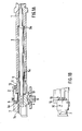
- a lock cylinder 1 is first provided with a lock 2 in a manner to be shown.
- the firing pin 3 is guided, which is provided with a firing pin nut 4 at its rear end.
- a counter bearing 5 for one acting on the firing pin 3 and this against the primer one in the barrel of a sleeve which is connected to the lock cylinder 1 is provided, inserted cartridge pressing impact spring 5a.
- the firing pin nut 4 interacts with a trigger stud 8, behind which it can be locked against the action of the striking spring 5a by actuating two corresponding tensioning curves (not shown) (FIGS. 2 and 3) and through which it can be released when the same is actuated, so that the Impact spring 5a can act freely on the firing pin 3.
- the design according to the invention provides that the lock 2 is connected to the locking cylinder 1 on the outside thereof.
- the locking cylinder 1 may have a bolt thread 11 in its rear part, which interacts with a corresponding nut thread 12 of the lock 2, so that lock 2 and lock cylinder 1 are firmly connected to one another. This creates 1 space for the separate counter bearing 5 in the rear interior of the locking cylinder that is axially slidably disposed in the locking cylinder 1 over a limited distance.
- a tension rod 6 cooperates with the counter bearing 5 on its side facing away from the striking spring 5a, which is guided in an axially parallel groove of the striker nut 4, protrudes beyond this from the lock 2 and on its rear, i.e. the opposite end 5 carries an upward pin 6a.
- the pin 6a engages in a cocking slide 7, with the inner end of which it cooperates.
- the cocking slide 7 has an actuating surface 7a which is anatomically adapted to the shape of the thumb on its upper side.
- a pivotable pawl 9 is provided on the tensioning slide 7 (in particular Figure 2b) which has a front hook 13. It is under the action of a spring 14 which presses it clockwise around a pin 15 so that the hook 13 engages around an edge 16 of the lock 2.
- An actuating button 17 is also provided, with which the latching between the hook 13 and the projection 16 of the lock leg 2 can be unlocked.
- Figure 1 shows the fired position of the firing pin after firing.
- the weapon is at rest.
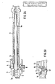
- the firing pin nut 4 with the firing pin 3 is moved back against the action of the firing pin spring 5a by means of a bolt handle 34 (FIG. 4 ff) over two corresponding tensioning curves (not shown) until the trigger stud 8 springs up from the firing pin nut and the latter in the tensioned position blocked ( Figure 2a).
- the cocking slide is locked with its pawl 9 on the projection 16 of the lock 2 and is thereby held in this position.
- the weapon In this position the weapon is cocked, the cock Slider is in its front, locked position, thus blocking the sliding counter bearing in a clamping position.
- the weapon can be fired by triggering the trigger tunnel 8.
- the latching of the cocking slide 7 can now be released by pressing the pawl 9 to the side.
- the cocking slide is released and can be pushed back under the action of the impact spring 5a via the movable counter bearing 5.
- the cocking slide 7 is pressed forward over the actuating surface 7a until the hook 13 of the pawl 9 engages behind the projection 16, so that the counter bearing 5 is also blocked again in its forward position in FIG. 2.
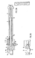
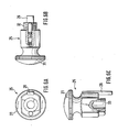
- FIG. 4 shows a lock 1 with a lock 2, a firing pin 3 guided axially in the locking cylinder 1 and a firing pin nut 4 connected to the firing pin nut 4.
- the firing pin nut 4 has on its side facing away from the firing pin 3 a turning handle 25 which is an attachment to the firing pin nut 4, for example via a screw, plug, or other connection, which in turn is attached by gluing, welding or the like.
- the Twist grip 25 has a stop pin 26 attached to its outside.
- the firing pin nut 4 has a locking lug 27 which cooperates with a trigger lug 8 which locks it.
- the stop pin 26 In the firing position of the rotary handle 25, the stop pin 26 lies behind the locking stud 27 (dashed line) and can follow the movement of the firing pin nut 4 and thus the firing pin 3 when fired.
- the stop pin 26 By turning the rotary handle 25 by about 90 degrees counterclockwise, the stop pin 26 is rotated and emerges from the position behind the locking stud 27. It is no longer behind the locking stud 27, but in an axial extension behind the lock 2.
- the trigger stud 8 By actuating the trigger stud 8 in the direction of arrow 29, the locking stud 27 is unlocked, whereupon the firing pin nut 4 and the firing pin 3 move in the direction of an inserted cartridge .
- the stop pin 26 strikes the outside of the lock 2 and thereby locks the further movement of the firing pin nut 4 and the firing pin 3.
- the lock 2 has a groove 30 in the stop, in which the stop pin 26 engages.
- the weapon is made ready to fire from this secured position by the user gripping the rotary handle 25 on the handle 31 and pulling it backwards against the pressure of the striker spring (not shown) until the trigger lug 8 in front of the locking lug 27 of the firing pin nut 4 jumps up.
- the rotary handle 25 90 degrees clockwise, the lock is released and the weapon is ready to fire.
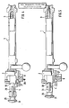
- FIGS. 6a to 6c show the rotary handle 25 designed as a rotating part in a more detailed view.
- the position is parallel to the axis of the stop pin 26 and the handle 31 delimiting the rotary handle 25.
- the side view of the rotary handle 25 shown in FIG. 6b shows the connecting device to the firing pin nut 4, which is designed as a threaded bolt 32.
- FIG. 6c shows another connecting device to the firing pin nut 4 with an arrangement 33 in the rotary handle 25.
Landscapes
- Engineering & Computer Science (AREA)
- General Engineering & Computer Science (AREA)
- Aiming, Guidance, Guns With A Light Source, Armor, Camouflage, And Targets (AREA)
- Toys (AREA)
- Telescopes (AREA)
Applications Claiming Priority (2)
| Application Number | Priority Date | Filing Date | Title |
|---|---|---|---|
| DE19863612386 DE3612386A1 (de) | 1986-04-12 | 1986-04-12 | Handspanneinrichtung fuer repetierbuechsen |
| DE3612386 | 1986-04-12 |
Publications (2)
| Publication Number | Publication Date |
|---|---|
| EP0243755A2 true EP0243755A2 (fr) | 1987-11-04 |
| EP0243755A3 EP0243755A3 (fr) | 1988-01-07 |
Family
ID=6298567
Family Applications (1)
| Application Number | Title | Priority Date | Filing Date |
|---|---|---|---|
| EP87105259A Withdrawn EP0243755A3 (fr) | 1986-04-12 | 1987-04-09 | Dispositif de sécurité pour fusils à répétition |
Country Status (2)
| Country | Link |
|---|---|
| EP (1) | EP0243755A3 (fr) |
| DE (1) | DE3612386A1 (fr) |
Cited By (2)
| Publication number | Priority date | Publication date | Assignee | Title |
|---|---|---|---|---|
| EP1126230A1 (fr) * | 2000-02-15 | 2001-08-22 | Hubert Bonderer | Mécanisme d'armement et de désarmement incorporable dans la culasse d'un fusil Mauser K98 |
| WO2008142520A1 (fr) * | 2007-05-17 | 2008-11-27 | Voere Holding Gmbh | Culasse mobile à dispositif de contrainte du ressort du percuteur par bouton poussoir |
Family Cites Families (8)
| Publication number | Priority date | Publication date | Assignee | Title |
|---|---|---|---|---|
| DE638052C (de) * | 1933-07-11 | 1936-11-09 | Waffenfabrik | Zylinderverschluss mit zentraler Sicherung und drehbarem Kammergriff, aber undrehbarer Kammer |
| DE1057915B (de) * | 1957-02-06 | 1959-05-21 | Horst Blaser | Handspannerschloss fuer Kipplaufwaffen |
| DE1056506B (de) * | 1957-07-26 | 1959-04-30 | Robert Huebner O H G | Spann- und Entspanneinrichtung fuer ein- oder mehrlaeufige Jagdgewehre |
| FR1506116A (fr) * | 1965-12-30 | 1967-12-15 | Mauser Werke Ag | Dispositif de sécurité coulissant pour culasses tournantes à cylindre d'armes |
| DE2927951A1 (de) * | 1978-08-02 | 1980-02-21 | Rudolf Ing Pasaurek | Drehkammerverschluss |
| AT363820B (de) * | 1980-03-14 | 1981-09-10 | Kepplinger Johann | Einrichtung zur spannungsaenderung der den schlagbolzen beaufschlagenden feder von handfeuerwaffen |
| DE3212467A1 (de) * | 1982-04-01 | 1984-04-05 | Gerd 4200 Oberhausen Fitscher | Zusatzsicherung fuer die repetierbuechse sauer modell 80 oder 90 |
| DE3302140A1 (de) * | 1983-01-22 | 1984-07-26 | Horst 7972 Isny Blaser | Schloss fuer repetierwaffen |
-
1986
- 1986-04-12 DE DE19863612386 patent/DE3612386A1/de not_active Withdrawn
-
1987
- 1987-04-09 EP EP87105259A patent/EP0243755A3/fr not_active Withdrawn
Cited By (3)
| Publication number | Priority date | Publication date | Assignee | Title |
|---|---|---|---|---|
| EP1126230A1 (fr) * | 2000-02-15 | 2001-08-22 | Hubert Bonderer | Mécanisme d'armement et de désarmement incorporable dans la culasse d'un fusil Mauser K98 |
| WO2008142520A1 (fr) * | 2007-05-17 | 2008-11-27 | Voere Holding Gmbh | Culasse mobile à dispositif de contrainte du ressort du percuteur par bouton poussoir |
| US8112927B2 (en) | 2007-05-17 | 2012-02-14 | Voere Holding Gmbh | Chamber lock having a pushbutton firing pin spring tensioning device |
Also Published As
| Publication number | Publication date |
|---|---|
| DE3612386A1 (de) | 1987-10-15 |
| EP0243755A3 (fr) | 1988-01-07 |
Similar Documents
| Publication | Publication Date | Title |
|---|---|---|
| DE2212211C3 (de) | Schlagbolzensicherungseinrichtung für Handfeuerwaffen | |
| DE3435809C2 (fr) | ||
| EP2487446B1 (fr) | Culasse pour fusil à répétition | |
| DE844558C (de) | Automatische Feuerwaffe mit einteiligem Verschluss | |
| CH620987A5 (fr) | ||
| DE7804099U1 (de) | Verschluss an einer selbsttaetigen feuerwaffe | |
| DE2106295A1 (de) | Sicherungsvorrichtung fur Revolver trommeln | |
| DE3120024C2 (de) | Selbsttätige Sicherungsvorrichtung für Handfeuerwaffen | |
| DE1067377B (de) | Bolzensetzgerat | |
| EP0036853A2 (fr) | Dispositif pour changer la tension du ressort de percussion des armes à feu portatives | |
| EP0243755A2 (fr) | Dispositif de sécurité pour fusils à répétition | |
| DE1478997C3 (de) | Verschlußausbildung für einen mit einem Trommelmagazin versehenen Brennkraftbolzens etz er | |
| DE2240878B2 (de) | Revolver | |
| DE579528C (de) | Schnellfeuerpistole | |
| DE2023816A1 (de) | Verschluß für automatische Feuerwaffen mit Puffereinrichtung | |
| DE567427C (de) | Verschlussverriegelungsvorrichtung fuer Feuerwaffen | |
| AT389759B (de) | Sicherungsvorrichtung fuer pistolen mit hahnschlagmechanismus | |
| DE1052274B (de) | Faustfeuerwaffe nach Art einer Maschinenpistole | |
| DE3132284A1 (de) | Sicherung an kurz- und langwaffen mit schlaghebel, insbesondere selbstladepistole | |
| DE1553869C3 (de) | Sicherungseinrichtung | |
| AT148246B (de) | Verschluß für Maschinenpistolen. | |
| AT212750B (de) | Abzugseinrichtung an automatischen Feuerwaffen | |
| DE1966147A1 (de) | Starrlauf-Federdruckluftgewehr | |
| DE2631256C3 (de) | Rückschlagsperre für die Spannvorrichtung einer Luftdruckwaffe mit verschiebbarem Kompressionszylinder | |
| DE623992C (de) | Sicherung fuer Zylinderverschlussgewehre |
Legal Events
| Date | Code | Title | Description |
|---|---|---|---|
| PUAI | Public reference made under article 153(3) epc to a published international application that has entered the european phase |
Free format text: ORIGINAL CODE: 0009012 |
|
| AK | Designated contracting states |
Kind code of ref document: A2 Designated state(s): AT BE CH DE ES FR GB GR IT LI LU NL SE |
|
| PUAL | Search report despatched |
Free format text: ORIGINAL CODE: 0009013 |
|
| AK | Designated contracting states |
Kind code of ref document: A3 Designated state(s): AT BE CH DE ES FR GB GR IT LI LU NL SE |
|
| STAA | Information on the status of an ep patent application or granted ep patent |
Free format text: STATUS: THE APPLICATION IS DEEMED TO BE WITHDRAWN |
|
| 18D | Application deemed to be withdrawn |
Effective date: 19880708 |