EP0241902A1 - Verfahren zur katalytischen Methanisierung eines Kohlenmonoxid, Kohlendioxid und Wasserstoff enthaltenden Synthesegases und Reaktor zur Methanisierung - Google Patents
Verfahren zur katalytischen Methanisierung eines Kohlenmonoxid, Kohlendioxid und Wasserstoff enthaltenden Synthesegases und Reaktor zur Methanisierung Download PDFInfo
- Publication number
- EP0241902A1 EP0241902A1 EP87105491A EP87105491A EP0241902A1 EP 0241902 A1 EP0241902 A1 EP 0241902A1 EP 87105491 A EP87105491 A EP 87105491A EP 87105491 A EP87105491 A EP 87105491A EP 0241902 A1 EP0241902 A1 EP 0241902A1
- Authority
- EP
- European Patent Office
- Prior art keywords
- synthesis gas
- area
- coolant
- methanation
- catalyst bed
- Prior art date
- Legal status (The legal status is an assumption and is not a legal conclusion. Google has not performed a legal analysis and makes no representation as to the accuracy of the status listed.)
- Withdrawn
Links
Images


Classifications
-
- B—PERFORMING OPERATIONS; TRANSPORTING
- B01—PHYSICAL OR CHEMICAL PROCESSES OR APPARATUS IN GENERAL
- B01J—CHEMICAL OR PHYSICAL PROCESSES, e.g. CATALYSIS OR COLLOID CHEMISTRY; THEIR RELEVANT APPARATUS
- B01J8/00—Chemical or physical processes in general, conducted in the presence of fluids and solid particles; Apparatus for such processes
- B01J8/02—Chemical or physical processes in general, conducted in the presence of fluids and solid particles; Apparatus for such processes with stationary particles, e.g. in fixed beds
- B01J8/0285—Heating or cooling the reactor
-
- C—CHEMISTRY; METALLURGY
- C07—ORGANIC CHEMISTRY
- C07C—ACYCLIC OR CARBOCYCLIC COMPOUNDS
- C07C1/00—Preparation of hydrocarbons from one or more compounds, none of them being a hydrocarbon
- C07C1/02—Preparation of hydrocarbons from one or more compounds, none of them being a hydrocarbon from oxides of a carbon
- C07C1/04—Preparation of hydrocarbons from one or more compounds, none of them being a hydrocarbon from oxides of a carbon from carbon monoxide with hydrogen
- C07C1/0405—Apparatus
- C07C1/042—Temperature controlling devices; Heat exchangers
-
- B—PERFORMING OPERATIONS; TRANSPORTING
- B01—PHYSICAL OR CHEMICAL PROCESSES OR APPARATUS IN GENERAL
- B01J—CHEMICAL OR PHYSICAL PROCESSES, e.g. CATALYSIS OR COLLOID CHEMISTRY; THEIR RELEVANT APPARATUS
- B01J2208/00—Processes carried out in the presence of solid particles; Reactors therefor
- B01J2208/00008—Controlling the process
- B01J2208/00017—Controlling the temperature
- B01J2208/00026—Controlling or regulating the heat exchange system
- B01J2208/00035—Controlling or regulating the heat exchange system involving measured parameters
- B01J2208/0007—Pressure measurement
-
- B—PERFORMING OPERATIONS; TRANSPORTING
- B01—PHYSICAL OR CHEMICAL PROCESSES OR APPARATUS IN GENERAL
- B01J—CHEMICAL OR PHYSICAL PROCESSES, e.g. CATALYSIS OR COLLOID CHEMISTRY; THEIR RELEVANT APPARATUS
- B01J2208/00—Processes carried out in the presence of solid particles; Reactors therefor
- B01J2208/00008—Controlling the process
- B01J2208/00017—Controlling the temperature
- B01J2208/00026—Controlling or regulating the heat exchange system
- B01J2208/00035—Controlling or regulating the heat exchange system involving measured parameters
- B01J2208/00088—Flow rate measurement
-
- B—PERFORMING OPERATIONS; TRANSPORTING
- B01—PHYSICAL OR CHEMICAL PROCESSES OR APPARATUS IN GENERAL
- B01J—CHEMICAL OR PHYSICAL PROCESSES, e.g. CATALYSIS OR COLLOID CHEMISTRY; THEIR RELEVANT APPARATUS
- B01J2208/00—Processes carried out in the presence of solid particles; Reactors therefor
- B01J2208/00008—Controlling the process
- B01J2208/00017—Controlling the temperature
- B01J2208/00106—Controlling the temperature by indirect heat exchange
- B01J2208/00115—Controlling the temperature by indirect heat exchange with heat exchange elements inside the bed of solid particles
- B01J2208/00141—Coils
-
- B—PERFORMING OPERATIONS; TRANSPORTING
- B01—PHYSICAL OR CHEMICAL PROCESSES OR APPARATUS IN GENERAL
- B01J—CHEMICAL OR PHYSICAL PROCESSES, e.g. CATALYSIS OR COLLOID CHEMISTRY; THEIR RELEVANT APPARATUS
- B01J2208/00—Processes carried out in the presence of solid particles; Reactors therefor
- B01J2208/00008—Controlling the process
- B01J2208/00017—Controlling the temperature
- B01J2208/00106—Controlling the temperature by indirect heat exchange
- B01J2208/00265—Part of all of the reactants being heated or cooled outside the reactor while recycling
- B01J2208/00274—Part of all of the reactants being heated or cooled outside the reactor while recycling involving reactant vapours
-
- B—PERFORMING OPERATIONS; TRANSPORTING
- B01—PHYSICAL OR CHEMICAL PROCESSES OR APPARATUS IN GENERAL
- B01J—CHEMICAL OR PHYSICAL PROCESSES, e.g. CATALYSIS OR COLLOID CHEMISTRY; THEIR RELEVANT APPARATUS
- B01J2219/00—Chemical, physical or physico-chemical processes in general; Their relevant apparatus
- B01J2219/00002—Chemical plants
- B01J2219/00004—Scale aspects
- B01J2219/00006—Large-scale industrial plants
Definitions
- the invention relates to a process for the catalytic methanation of a synthesis gas containing carbon monoxide, carbon dioxide and hydrogen.
- the methanation takes place in a solid catalyst bed which is cooled by a coolant.
- the synthesis gas flows successively first through an input area for the synthesis gas, then through an area with a high synthesis gas temperature, which is referred to below as the hot-spot area, and finally through an exit area in which the synthesis gas temperatures essentially decrease.
- the coolant that dissipates the heat generated in the solid catalyst bed is used to generate steam and is converted into superheated steam.
- the conversion of a synthesis gas containing carbon monoxide, carbon dioxide and hydrogen is, since it is exothermic, for recovery of energy usable. It is known to carry out the conversion of the synthesis gases in internally cooled reactors containing catalysts. To generate steam, the internally cooled reactors have cooling systems through which coolants are arranged, which are arranged within the catalyst bed. The cooling ensures that a maximum operating temperature for the catalyst is not exceeded so that the catalyst material remains stable.
- the coolant overheats in the heat exchange with the synthesis gas flowing out of the adiabatic reactor.
- the methanation process known from DE-PS 31 12 991 does not differ from the aforementioned process.
- the first is used to generate steam at the evaporation temperature
- the second reactor is used as an adiabatic reactor
- the third reactor is used to heat the coolant to the evaporation temperature.
- the synthesis gas flowing out of the adiabatic reactor is used to overheat the coolant.
- the object of the invention is to methanation propose a single-stage process of synthesis gas that allows both the generation of superheated steam and the production of a methane-rich product gas and ensures that an adequate operating temperature is not impaired within the catalyst bed, even in the hot spot area, which does not impair the stability of the catalyst.
- a low maximum temperature in the hot spot area can be achieved by introducing the steam formed in the exit area into the entrance area of the catalyst bed and flowing through the entrance area and the hot spot area in cocurrent to the synthesis gas, claim 3.
- a further reduction in the maximum temperature arises when the hot-spot area is also used to evaporate the coolant, claim 4.
- the heat of reaction generated in the hot-spot area not only serves to generate superheated steam, part of the heat also becomes evaporation of the coolant, which facilitates the controllability of the desired process.
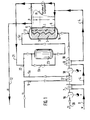
- FIG. 1 shows a methanation plant with a methanization reactor 1 which contains a catalyst bed 2 and is traversed by a cooling system 3.
- the coolant flows through the cooling system 3 in counterflow to the synthesis gas.
- the direction of flow of the coolant in coolant lines 4 is marked in the drawing with dark filled arrows, the flow direction of the synthesis gas in synthesis gas lines 5 with bright arrows.
- Water serves as the coolant, which first passes through two preheaters 7, 8 at its coolant inlet 6 before entering the methanation reactor. In the preheaters, the water flowing in via the inflow 9 at room temperature is preheated to the required inlet temperature at the coolant inlet 6 in the heat exchange with product gas which flows out of the methanation reactor in product gas lines 10.
- the water is then in the Cooling system 3 of the methanation reactor evaporates by absorbing the heat generated in the catalyst bed 2 during the methanation of the synthesis gas and then overheats.
- the superheated steam flows from the coolant outlet 11 out of the methanation reactor into a steam line 12.
- the methanation reactor 1 has three zones with a characteristic temperature profile in the catalyst bed 2. According to this temperature profile in the catalyst bed, the methanation reactor can be divided into an input area A with a steeply rising temperature, a hot spot area B with a temperature maximum in the catalyst bed and an output area C with a steadily decreasing temperature with stable operating behavior. These three zones and their characteristic temperature profile in the flow direction of the synthesis gas are shown schematically in FIG. 1 over the length of the catalyst bed.
- the entrance area A is characterized by rising synthesis gas temperatures from approx. 2500C to approx. 450 ° C, the hot spot area by synthesis gas temperatures between 450 ° C and 750 C and the exit area by falling temperatures from approx. 450 ° C to approx. 250 ° C.
- the cooling system 3 penetrates in the flow direction of the cooling seen both the exit area C, the hot spot area B and the entry area A of the methanation reactor.
- the synthesis gas flows in the methanation reactor in counterflow to the coolant. It is introduced into the methanation reactor at the synthesis gas inlet 13 and is initially strongly heated in the inlet area A when the exothermic methanation reaction starts in the catalyst bed 2.
- the synthesis gas reaches its maximum temperature. It is converted to product gas and, after cooling and further reaction, leaves the methanation reactor in exit area C as a product gas rich in methane.
- the product gas flows from the product gas outlet 14 out of the methanation reactor into the product gas line 10.
- the heat present there is removed from the catalyst bed by evaporating the coolant in the cooling system 3.
- the heat generated is removed from the catalyst bed by overheating the steam formed.
- the cooling system 3 thus acts in the exit area C as an evaporator 15 for the coolant, in the hot spot area B as a superheater 16 for the coolant vapor produced in the evaporator.
- Evaporator 15 and superheater 16 go in the methanation reactor shown in FIG directly into each other. There is therefore no fixed boundary between the evaporator and superheater in the cooling system 3. It is essential, however, that within the part of the cooling system 3, which acts as a superheater 16, the reaction heat generated in the hot spot area B is dissipated and is used to overheat the steam formed in the evaporator 15 of the cooling system 3. The temperature of the coolant thus rises in the superheater 16. In the exemplary embodiment according to FIG. 1, in which the cooling system also traverses the input area A, it only drops slightly in this area toward the coolant outlet 11.
- the coolant in the evaporator 15 is at a constant temperature, namely at the evaporation temperature which corresponds to its pressure.
- the evaporator 15 and superheater 16 can therefore be distinguished from one another by their temperature profile for the coolant.
- the product gas flowing out of the product gas outlet 14 is led in the product gas line 10 to the preheaters 7 and 8 and exchanges part of its heat here - as already mentioned - with the coolant flowing into the methanation system.
- a preheater 17 is also provided in the product gas line 10 for the synthesis gas, which flows into the methanation plant, and liquid separators 18, 19 are used to separate water from the product gas.
- the dry methane-rich product gas is withdrawn from the methanation plant at the gas outlet 20.
- the superheated steam formed in the methanation reactor 1 is removed in the exemplary embodiment according to FIG. 1 via the steam line 12 as a working medium and fed, for example, to steam turbines for generating electrical energy.
- the superheated steam after mixing with preheated coolant, which is removed from the coolant line 4 by means of a feed line 21 ′, can be introduced as saturated steam via a discharge line 21 into the synthesis gas line 5 into the synthesis gas flowing here to the methanation reactor via the preheater 17.
- the synthesis gas can be introduced in whole or in part into a conversion reactor 23 in order to partially convert the carbon monoxide contained in the synthesis gas to carbon dioxide.
- the proportion of synthesis gas which is not to be converted flows into the methanization reactor 1 via an adjustable bypass 5b parallel to the conversion reactor 23 together with the converted part of the synthesis gas.
- the methanation reactor 1 ' Unlike the Methanmaschinesanla e g according to figure 1, the methanation reactor 1 'according to Figure 2 an evaporator 15', and a superheater 16 ', which form separate from each other in the methanization reactor tube system.
- a steam chamber 24 is connected between the evaporator 15 'and the superheater 16', in which the steam flowing in from the evaporator 15 'collects via a connecting line 25 and entrained, still undevaporated cooling liquid is separated.
- a steam supply line 26 is connected, which conducts the dry steam collecting here to the superheater 16 '.
- a removal line 21 ' leads to the connection 22 in part 5a of the synthesis gas line 5. Saturated steam is thus introduced into the synthesis gas as in the exemplary embodiment according to FIG.
- the steam chamber 24 is arranged outside the methanation reactor 1. Deviating from this, it is also possible to use the steam chamber as an integrated component within the methanation reactor. In this case, the steam chamber is expediently arranged above the catalyst bed and the synthesis gas flows around it, which enters the methanation reactor.
- the steam superheated in superheater 16 ' also flows in the methanation plant according to FIG. to a steam turbine.
- FIG. 2 for the rest, the same reference numerals as in FIG. 1 are given for all parts of the plant which unchanged correspond to the parts of FIG. 1.
- evaporators 15, 15 'and superheaters 16, 16' are only shown schematically. They can also be laid in the catalyst bed in a different way than that shown in FIGS. 1 and 2. However, there is always an evaporator in the exit area C of the methanation reactor and a superheater in the hot spot area B. Special embodiments for the arrangement of the evaporator and superheater are shown in FIGS. 3 to 8. These figures also show the temperature profiles that occur with appropriate heat dissipation by the coolant in the synthesis gas or in the catalyst bed 2. The temperatures are entered both for the synthesis gas and for the coolant over the reactor length in the flow direction of the synthesis gas or the coolant.
- the temperature profile for the synthesis gas over the reactor length is shown in the figures with a solid line, the temperature profile for the coolant with a dashed line.
- the direction of flow of the coolant is always directed opposite to the direction of flow of the synthesis gas in the evaporator.
- the coolant vapor can also be conducted in direct current to the synthesis gas, as is shown in the exemplary embodiment according to FIG. 7.
- the flow direction for coolant or coolant vapor in the evaporator and superheater and the flow direction for the synthesis gas in the catalyst bed are marked in FIGS. 3 to 8 in the same way as in FIGS. 1 and 2 in each case by dark flow arrows (coolant) or bright flow arrows (synthesis gas) .
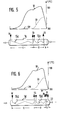
- FIG. 3 shows a methanization reactor 1 a in which a cooling system 3 a runs through the catalyst bed 2 from the exit area C to the hot spot area B.
- the cooling system 3a serves as an evaporator 15a, in the hot spot area as a superheater 16a.
- the cooling water flows into the evaporator 15a at a temperature below the evaporation temperature, is brought to the evaporation temperature in the evaporator, is evaporated and is then overheated in the superheater 16a.
- the cooling water in exit area C, the steam in hot spot area B absorbs the heat of reaction. In the hot In the spot area, the steam is heated to a temperature of approx. 500 ° C at 100 bar.
- the catalyst bed remains below the adiabatic temperature, which is below 800 ° C. for the synthesis gas used in the exemplary embodiment.
- an inconsistency occurs due to the heat absorbed by the evaporator at constant boiling temperature, primarily due to the design, in particular when the methanation reactor is designed in the manner described in DE-OS 32 47 821.
- the temperature increases again slightly and then drops to values below 400 ° C.
- the methanation reactor 1b has a cooling system 3b which runs through the entire methanation reactor from its exit area C via the hot-spot area B to the entrance area A.
- the cooling system 3b thus corresponds to the cooling system 3 shown in FIG. 1. From the associated temperature profile in FIG. 4, it can be seen that in principle a temperature profile comparable to that of the methanation reactor according to FIG. 3 is established. However, the superheated steam is cooled in the inlet area C by the incoming synthesis gas somewhat below its maximum temperature of 500 ° C. What is striking in comparison to the exemplary embodiment according to FIG. 3, however, is the excessive increase in the maximum temperature of the synthesis gas in the hot spot area.
- the synthesis gas is heated in the catalyst bed 2 to a temperature of about 770 ° C.
- the initial temperature of the product gas is thus also slightly higher than the initial temperature of the product gas in the exemplary embodiment according to FIG. 3, but it is still below 400 ° C.
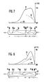
- the methanation reactor 1c has pipeline systems for evaporators 15c and superheaters 16c which are separate from one another.
- the evaporator 14c is installed exclusively in the exit area C of the methanation reactor, the hot spot area B is only cooled by steam overheating.
- the coolant enters the evaporator in this and in the following exemplary embodiments already at the evaporation temperature.
- approximately the same temperatures are set in the hot spot area as in the exemplary embodiment according to FIG. 3.
- the synthesis gas is heated to a maximum of approximately 730 ° C. in the methanation reactor. However, the product gas is cooled to a greater extent and the product gas is withdrawn from the methanation reactor at a temperature of approximately 310 ° C.
- the methanation reactor 1d shown in FIG. 6 is in terms of evaporator 15d and superheater 16d equipped in the same way as the methanization reactor 1c according to FIG. 5. In addition, however, it has a coolant preheater 27 in the entrance area. In the coolant preheater, the coolant is brought to the evaporation temperature before entering the evaporator 15d and only then flows to the coolant inlet 6 of the evaporator. The coolant is led in the coolant preheater in countercurrent to the synthesis gas. This cooling of the synthesis gas already in the entrance area A limits the maximum heating of the catalyst bed in the methanation reactor to approximately 7000C.
- the steam to be superheated is conducted in the superheater 16e in cocurrent to the synthesis gas.
- the superheater 16e is arranged in the hot spot area and in the entrance area of the methanation reactor le.
- the steam to be superheated is supplied to the entrance area at boiling temperature.
- the steam is heated to a temperature of about 500 ° C. at 100 bar.
- the product gas flows out of the methanation reactor at a temperature of about 310 ° C.
- the evaporator 15f of the cooling system extends over the entire length of the catalyst bed from the exit area C via the hot spot area B to the entrance area A of the methanation reactor 1f.
- the superheater 16f is arranged in the hot spot area, but it also projects into the exit area C of the methanation reactor, so that the superheater and the evaporator overlap.
- the heat transfer necessary in this case to superheater 16f and evaporator 15f can expediently be achieved in that the steam superheating lines run inside the catalyst tubes containing the catalyst particles, so that the heat of reaction reacts both to the coolant to be evaporated, which surrounds the catalyst tube, and to the steam to be overheated can be dispensed.
- the maximum temperature of the synthesis gas can be reduced to 650 ° C without the quality of the working fluid, namely up to 500 ° C at 100 bar superheated steam, deteriorating and without reducing the methane content in the product gas.
- Methanization reactors of this type are therefore optimally suited for carrying out a methanization reaction.
- the mass flow, the gas fractions in synthesis gas and product gas, the temperatures and pressures are entered for the latter case of the cooling system according to FIG. 8.
- 1.27 kg / s synthesis gas is introduced into the methanation plant, which contains the following gas fractions in vol%: 1% H 2 0 ; 13.51 % CH 4 ; 8.93% CO; 10.07% CO 2 ; 67.48% H 2 .
- the synthesis gas is heated in the preheater 17 from approximately 180 ° C. and mixed with saturated steam in part 5a of the synthesis gas line 5.
- the entire synthesis gas is converted in the exemplary embodiment with the bypass 5b closed and further heated in the process. It flows into the methanation reactor 1 ′ at a temperature of 280 ° C. at synthesis gas inlet 13.
- a product gas is obtained at the product gas outlet 14 which is 58.66% H 2 0; 39.13% CH 4 ; 0% C0; Contains 0.35% C0 2 and 1.89% H 2 .
- the product gas flows out of the methanation reactor at a pressure of 47 bar and a temperature of 350 ° C.
- the mass flow of the product gas in the product gas line is 1.67 kg / s.
- a product gas with a proportion of 94.6% CH 4 is obtained at the gas outlet 20.
- 1.89 kg / s of cooling water with a temperature of approx. 20 ° C. is fed into the coolant line.
- the cooling water is heated in the preheaters 7 and 8 to a temperature of 2600C, with which it is introduced into the steam chamber 24 in the exemplary embodiment.
- the cooling water is brought to a temperature of 3100C at 100 bar and introduced into the evaporator 15 ', in which it evaporates at an evaporation temperature of 311 ° C.
- the steam formed is returned to the steam chamber 24 and flows via the connecting line 25 into the superheater 16 '.
- the steam is superheated to 500 ° C at 100 bar.
- 1.49 kg / s superheated steam is removed from the methanation plant.
- the remaining steam of 0.4 kg / s flows from the steam chamber 24 via the extraction line 21 'at the connection 22 into the synthesis gas.
- the data entered in FIG. 2 for synthesis gas and coolant also apply, with slight deviations, to the methanation plant according to FIG. 1.
- they are also applicable to the design Examples according to FIGS. 3 to 7.
- To be taken into account here are only the different temperatures for the product gas in the exemplary embodiments according to FIGS. 3 and 4 and the temperature remaining below 500 ° C. in the exemplary embodiment according to FIG. 4 for the superheated steam flowing out from the superheater .
- the temperature profiles shown in FIGS. 3 to 7 are quantitative to the extent that they are semi-quantitative graphs.
Landscapes
- Chemical & Material Sciences (AREA)
- Organic Chemistry (AREA)
- Chemical Kinetics & Catalysis (AREA)
- Engineering & Computer Science (AREA)
- General Chemical & Material Sciences (AREA)
- Oil, Petroleum & Natural Gas (AREA)
- Organic Low-Molecular-Weight Compounds And Preparation Thereof (AREA)
- Devices And Processes Conducted In The Presence Of Fluids And Solid Particles (AREA)
Abstract
Description
- Die Erfindung bezieht sich auf ein Verfahren zur katalytischen Methanisierung eines Kohlenmonoxid, Kohlendioxid und Wasserstoff enthaltenden Synthesegases. Die Methanisierung findet in einem Feststoff-Katalysatorbett statt, das von einem Kühlmittel gekühlt wird. Das Synthesegas durchströmt im Katalysatorbett nacheinander zunächst einen Eingangsbereich für das Synthesegas, anschließend einen Bereich mit hoher Synthesegastemperatur, der im folgenden als Hot-Spot-Bereich bezeichnet wird, und schließlich einen Ausgangsbereich, in dem die Synthesegastemperaturen im wesentlichen absinken. Das Kühlmittel, das die im Feststoff-Katalysatorbett entstehende Wärme abführt, dient der Erzeugung von Dampf und wird in überhitzten Dampf-überführt.
- Die Umwandlung eines Kohlenmonoxid, Kohlendioxid und Wasserstoff enthaltenden Synthesegases ist, da sie exotherm verläuft, zur Gewinnung von Energie nutzbar. Es ist bekannt, die Umwandlung der Synthesegase in Katalysatoren enthaltenden innengekühlten Reaktoren durchzuführen. Zur Dampferzeugung weisen die innengekühlten Reaktoren kühlmitteldurchströmte Kühlsysteme auf, die innerhalb des Katalysatorbettes angeordnet sind. Durch die Kühlung wird dafür Sorge getragen, daß eine für den Katalysator maximal zulässige Betriebstemperatur nicht überschritten wird, damit das Katalysatormaterial stabil bleibt.
- Innengekühlte Reaktoren zur Methanisierung von Sythesegas werden in B. Höhlein, "Methanisierungsverfahren unter Berücksichtigung der Arbeiten zum NFE-Projekt", Berichte der Kernforschungsanlage Jülich, JÜL-1589, Mai 1979 beschrieben. In dieser Veröffentlichung gezeigte Anlagen, insbesondere Bild 10, erlauben eine Führung des Prozesses ohne Rückleiten von Gas mittels störanfälligen Kompressoren. Aus der DE-OS 29 49 588 ist es zur Erzeugung überhitzten Sattdampfes bekannt, mehrere Reaktoren hintereinander zu schalten, wobei einer der Reaktoren, der vom Synthesegas zuerst durchströmte Reaktor, als adiabater Reaktor, der nachfolgende Reaktor als innengekühlter Reaktor ausgebildet ist. Die im innengekühlten Reaktor entstehende Wärme wird durch Verdampfen des Kühlmittels abgeführt. Die Überhitzung des Kühlmittels erfolgt im Wärmeaustausch mit dem dem adiabaten Reaktor entströmenden Synthesegas. Hinsichtlich der Dampferzeugung im innengekühlten Reaktor und der Überhitzung des Dampfes mit Synthesegas, das den adiabaten Reaktor verläßt, unterscheidet sich das aus DE-PS 31 12 991 bekannte Methanisierungsverfahren vom vorgenannten Verfahren nicht. Von den bei diesem bekannten Verfahren vom Synthesegas hintereinander durchströmten drei Reaktoren wird der erste zur Erzeugung von Dampf bei Verdampfungstemperatur, der zweite Reaktor als adiabater Reaktor, der dritte Reaktor zur Aufheizung des Kühlmittels bis auf Verdampfungstemperatur genutzt. Zur Überhitzung des Kühlmittelss dient das vom adiabaten Reaktor abströmende Synthesegas.
- Abgesehen vom apparativen Aufwand mit mehreren hintereinander zu durchströmenden Reaktoren und der Anordnung von zusätzlichen Wärmetauschern zur Überhitzung des erzeugten Dampfes weisen die bekannten Verfahren auch Nachteile hinsichtlich der Verfahrensführung auf. Es ist notwendig, um Überhitzungen der Katalysatoren zu vermeiden, das Synthesegas zwischen den einzelnen Reaktoren zwischenzukühlen, so daß der Methanisierungsprozeß insgesamt nur schrittweise durchführbar ist.
- Aufgabe der Erfindung ist es, zur Methanisierung von Synthesegas ein einstufiges Verfahren vorzuschlagen, das sowohl die Erzeugung überhitzten Dampfes als auch die Erzeugung eines methanreichen Produktgases erlaubt und gewährleistet, daß innerhalb des Katalysatorbettes auch im Hot- Spot-Bereich eine ausreichende, die Stabilität des Katalysators nicht beeinträchtigende Betriebstemperatur eingehalten wird.
- Diese Aufgabe wird bei einem Verfahren der eingangs erwähnten Art gemäß der Erfindung durch die in Patentanspruch 1 angegebenen Merkmale gelöst. Danach wird das Kühlmittel zumindest im Ausgangsbereich des Katalysatorbettes bei Siedetemperatur verdampft, während im Hot-Spot-Bereich der gebildete Dampf überhitzt wird. Durch diese Verfahrensführung mit einer weitgehend konstanten Temperatur des Kühlmittels im Ausgangsbereich und der Überhitzung des gebildeten Dampfes im Hot-Spot-Bereich läßt sich das Verfahren in einfacher Weise im optimalen Betriebsbereich des Katalysatorbettes führen.
- In weiterer Ausbildung der Erfindung gemäß Patentanspruch 2 ist vorgesehen, das Kühlmittel im Ausgangsbereich des Katalysatorbettes im Gegenstrom zum Synthesegas zu führen und mit einer Temperatur in den Ausgangsbereich einzuleiten, die unterhalb der Siedetemperatur des Kühlmittels liegt. Auf diese Weise läßt sich am Ausgang des Katalysatorbettes auch für das Synthesegas eine niedrige Ausgangstemperatur erreichen, so daß das Komponentengleichgewicht im Synthesegas in gewünschter Weise zugunsten von Methan verschiebbar ist.
- Eine niedrige Maximaltemperatur im Hot-Spot-Bereich läßt sich dadurch erreichen, daß der im Ausgangsbereich gebildete Dampf im Eingangsbereich des Katalysatorbettes eingeführt wird und im Gleichstrom zum Synthesegas den Eingangsbereich und den Hot-Spot-Bereich durchströmt, Patenanspruch 3. Eine weitere Erniedrigung der Maximaltemperatur ergibt sich bei einer Nutzung auch des Hot-Spot-Bereiches zur Verdampfung des Kühlmittels, Patentanspruch 4. Für diesen zuletzt genannten Fall dient die im Hot-Spot-Bereich entstehende Reaktionswärme nicht nur zur Erzeugung überhitzten Dampfes, ein Teil der Wärme wird auch zur Verdampfung des Kühlmittels abgegeben, was die Regelbarkeit des gewünschten Prozeßverlaufes erleichtert.
- Im folgenden wird das erfindungsgemäße Verfahren und ein Reaktor zur Durchführung dieses Verfahrens, der ebenfalls Gegenstand der Erfindung ist, anhand von Ausführungsbeispielen näher erläutert. Es zeigen im einzelnen
- Figur 1 Fließbild einer einstufigen Methanisierungsanlage;
- Figur 2 Einstufige Methanisierungsanlage mit Dampfkammer zwischen Verdampfer und Überhitzer;
- Figur 3 Temperaturverlauf im Katalysatorbett eines Methanisierungsreaktors bei Strömungsführung des Kühlmittels im Gegenstrom zum Synthesegas; die Eintrittszone wird vom Kühlmittel nicht durchströmt;
- Figur 4 Temperaturverlauf im Katalysatorbett bei Strömungsführung des Kühlmittels im Gegenstrom zum Synthesegas mit einem Kühlsystem, das sich im Methanisierungsreaktor vom Ausgangsbereich bis zum Eingangsbereich erstreckt;
- Figur 5 Temperaturverlauf im Katalysatorbett eines Methanisierungsreaktors, der einen vom Verdampfer getrennt angeordneten Überhitzer enthält, bei Strömungsführung des Kühlmittels im Gegenstrom zum Synthesegas; die Eintrittszone wird vom Kühlmittel nicht durchströmt;
- Figur 6 Temperaturverlauf im Katalysatorbett eines Methanisierungsreaktors mit getrennt angeordnetem Verdampfer -und Überhitzer und zusätzlicher Kühlung des Eingangsbereiches des Methanisierungsreaktors (der Eingangsbereich dient zur Kühlmittelveränderung);
- Figur 7 Temperaturverlauf im Katalysatorbett eines Methanisierungsreaktors mit getrennt angeordnetem Verdampfer und Überhitzer, wobei der Überhitzer vom zu überhitzenden Dampf im Gleichstrom zum Synthesegas durchströmt wird;
- Figur 8 Temperaturverlauf im Katalysatorbett bei Verdampfung des Kühlmittels auch im Hot-Spot- und Eingangsbereich des Mathanisierungsreaktors.
- Figur 1 zeigt eine Methanisierungsanlage mit einem Methanisierungsreaktor 1, der ein Katalysatorbett 2 enthält und von einem Kühlsystem 3 durchzogen ist. Das Kühlmittel durchströmt das Kühlsystem 3 im Gegenstrom zum Synthesegas. Die Strömungsrichtung des Kühlmittels in Kühlmittelleitungen 4 ist in der Zeichnung jeweils mit dunkel ausgefüllten Pfeilen, die Strömungsrichtung des Synthesegases in Synthesegasleitungen 5 mit hellen Pfeilen markiert. Als Kühlmittel dient Wasser, das vor Eintritt in den Methanisierungsreaktor an dessen Kühlmitteleingang 6 zunächst zwei Vorwärmer 7, 8 passiert. In den Vorwärmern wird das über den Zufluß 9 mit Raumtemperatur einströmende Wasser im Wärmeaustausch mit Produktgas, das vom Methanisierungsreaktor in Produktgasleitungen 10 abströmt, auf die erforderliche Eingangstemperatur am Kühlmitteleingang 6 vorgewärmt. Das Wasser wird dann im Kühlsystem 3 des Methanisierungsreaktors durch Aufnahme der im Katalysatorbett 2 bei der Methanisierung des Synthesegases entstehenden Wärme verdampft und anschließend überhitzt. Der überhitzte Dampf strömt vom Kühlmittelausgang 11 aus dem Methanisierungsreaktor in eine Dampfleitung 12 ab.
- In Strömungsrichtung des Synthesegases gesehen weist der Methanisierungsreaktor 1 drei Zonen mit charakteristischem Temperaturverlauf im Katalysatorbett 2 auf. Entsprechend diesem Temperaturprofil im Katalysatorbett läßt sich der Methanisierungsreaktor bei stabilem Betriebsverhalten in einen Eingangsbereich A mit steil ansteigender Temperatur, in einen Hot-Spot-Bereich B mit einem Temperaturmaximum im Katalysatorbett und einen Ausgangsbereich C mit stetig fallender Temperatur einteilen. Diese drei Zonen und ihr charakteristischer Temperaturverlauf in Strömungsrichtung des Synthesegases gesehen sind in Figur 1 über der Länge des Katalysatorbettes schematisch dargestellt. Der Eingangsbereich A ist dabei gekennzeichnet durch ansteigende Synthesegastemperaturen von ca. 2500C bis auf etwa 450°C, der Hot-Spot-Bereich durch Synthesegastemperaturen zwischen 450°C und 750 C und der Ausgangsbereich durch abfallende Temperaturen von ca. 450°C bis etwa 250°C.
- Im Ausführungsbeispiel nach Figur 1 durchdringt das Kühlsystem 3 in Strömungsrichtung des Kühlmittels gesehen sowohl den Ausgangsbereich C, den Hot-Spot-Bereich B und den Eingangsbereich A des Methanisierungsreaktors. Das Synthesegas strömt im Methanisierungsreaktor im Gegenstrom zum Kühlmittel. Es wird am Synthesegaseingang 13 in den Methanisierungsreaktor eingeführt und im Eingangsbereich A bei einsetzender exothermer Methanisierungsreaktion im Katalysatorbett 2 zunächst stark erhitzt. Im Hot-Spot-Bereich B erreicht das Synthesegas seine maximale Temperatur. Es wird zu Produktgas umgesetzt und verläßt den Methanisierungsreaktor nach Abkühlung und weiterer Umsetzung im Ausgangsbereich C als methanreiches Produktgas. Das Produktgas strömt vom Produktgasausgang 14 aus dem Methanisierungsreaktor in die Produktgasleitung 10 ab.
- Zur Kühlung des Ausgangsbereiches C des Methanisierungsreaktors wird die dort vorhandene Wärme aus dem Katalysatorbett durch Verdampfen des Kühlmittels im Kühlsystem 3 abgeführt. Im Hot-Spot-Bereich B wird die entstehende Wärme dem Katalysatorbett durch Überhitzen des gebildeten Dampfes entzogen. Das Kühlsystem 3 wirkt somit im Ausgangsbereich C als Verdampfer 15 für das Kühlmittel, im Hot-Spot-Bereich B als Überhitzer 16 für den im Verdampfer produzierten Kühlmitteldampf.
- Verdampfer 15 und Überhitzer 16 gehen bei dem in Figur 1 gezeigten Methanisierungsreaktor unmittelbar ineinander über. Es besteht daher im Kühlsystem 3 keine feste Begrenzung zwischen Verdampfer und Überhitzer. Wesentlich ist jedoch, daß innerhalb des Teils des Kühlsystems 3, der als Überhitzer 16 wirkt, die im Hot-Spot-Bereich B entstehende Reaktionswärme abgeführt wird und zur Überhitzung des im Verdampfer 15 des Kühlsystem 3 gebildeten Dampfes dient. Im Überhitzer 16 steigt somit die Temperatur des Kühlmittels an. Sie fällt beim Ausführungsbeispiel nach Figur 1, bei dem das Kühlsystem auch den Eingangsbereich A durchzieht, lediglich in diesem Bereich zum Kühlmittelausgang 11 hin leicht ab. Im Verdampfer 15 befindet sich das Kühlmittel hingegen auf konstanter Temperatur, nämlich auf der Verdampfungstemperatur, die seinem Druck entspricht. Beim Kühlsystem 3 nach Figur 1 lassen sich daher Verdampfer 15 und Überhitzer 16 durch ihren Temperaturverlauf für das Kühlmittel voneinander unterscheiden.
- Das vom Produktgasausgang 14 abströmende Produktgas wird in der Produktgasleitung 10 zu den Vorwärmern 7 und 8 geführt und tauscht hier einen Teil seiner Wärme - wie bereits erwähnt - mit dem in die Methanisierungsanlage einströmenden Kühlmittel aus. Zusätzlich zu diesen Vorwärmern 7, 8 sind in die Produktgasleitung 10 noch ein Vorwärmer 17 für das Synthesegas vorgesehen, das in die Methanisierungsanlage einströmt, sowie Flüssigkeitsabscheider 18, 19 zur Abscheidung von Wasser aus dem Produktgas eingesetzt. Das trockene methanreiche Produktgas zieht am Gasaustritt 20 aus der Methanisierungsanlage ab.
- Der im Methanisierungsreaktor 1 gebildete überhitzte Dampf wird im Ausführungsbeispiel nach Figur 1 über die Dampfleitung 12 als Arbeitsmittel entnommen und beispielsweise Dampfturbinen zur Erzeugung elektrischer Energie zugeführt. Zu einem Teil kann der überhitzte Dampf nach Vermischen mit vorgewärmtem Kühlmittel, das mittels einer Zuleitung 21' aus der Kühlmittelleitung 4 entnommen wird, als Sattdampf über eine Entnahmeleitung 21 in die Synthesegasleitung 5 in das hier dem Methanisierungsreaktor über den Vorwärmer 17 zuströmende Synthesegas eingeleitet werden. Im Ausführungsbeispiel befindet sich hierzu für die Entnahmeleitung 21 ein Anschluß 22 im Teil 5a der Synthesegasleitung 5. Nach Zumischen des Wasserdampfes kann das Synthesegas ganz oder teilweise in einen Konvertierungsreaktor 23 eingeführt werden, um das im Synthesegas enthaltene Kohlenmonoxid teilweise zu Kohlendioxid umzusetzen. Der Anteil nicht zu konvertierenden Synthesegases strömt über einen regulierbaren Bypaß 5b parallel zum Konvertierungsreaktor 23 zusammen mit dem konvertierten Teil des Synthesegases in den Methanisierungsreaktor 1 ein.
- Anders als die Methanisierungsanlage nach Figur 1 weist der Methanisierungsreaktor 1' nach Figur 2 einen Verdampfer 15' und eine Überhitzer 16' auf, die im Methanisierungsreaktor voneinander getrennte Rohrsystem bilden. Zwischen Verdampfer 15' und Überhitzer 16' ist eine Dampfkammer 24 geschaltet, in der sich der vom Verdampfer 15' über eine Verbindungsleitung 25 einströmende Dampf sammelt und mitgerissene noch unverdampfte Kühlflüsssigkeit abgeschieden wird. An der höchsten Stelle der Dampfkammer 24 ist eine Dampfzuleitung 26 angeschlossen, die den sich hier sammelnden trockenen Dampf zum Überhitzer 16' leitet. Von der Dampfkammer 24 führt in gleicher Weise wie beim Ausführungsbeispiel nach Figur 1 auch eine Entnahmeleitung 21' zum Anschluß 22 im Teil 5a der Synthesegasleitung 5. Es wird somit ebenso wie im Ausführungsbeispiel nach Figur 1 Sattdampf in das Synthesegas eingeführt.
- Beim Ausführungsbeispiel ist die Dampfkammer 24 außerhalb des Methanisierungsreaktors 1 angeordnet. Abweichend hiervon ist es auch möglich, die Dampfkammer innerhalb des Methanisierungsreaktors als integrierter Bestandteil einzusetzen. Die Dampfkammer wird in diesem Fall zweckmäßig oberhalb des Katalysatorbettes angeordnet und vom Synthesegas umströmt, das in den Methanisierungsreaktor eintritt.
- Der im Überhitzer 16' überhitzte Dampf strömt auch bei der Methanisierungsanlage nach Figur 2 als Arbeitsmittel z.B. zu einer Dampfturbine. In Figur 2 sind im übrigen für alle Anlagenteile, die unverändert den Anlagenteilen der Figur 1 entsprechen, gleiche Bezugszeichen wie in Figur 1 angegeben.
- In Figuren 1 und 2 sind Verdampfer 15, 15' und Überhitzer 16, 16' nur schematisch dargestellt. Sie lassen sich im Katalysatorbett auch in anderer Weise verlegen, als dies in Figuren 1 und 2 gezeigt ist. Stets befindet sich jedoch ein Verdampfer im Ausgangsbereich C des Methanisierungsreaktors und ein Überhitzer im Hot-Spot-Bereich B. Spezielle Ausführungsformen für die Anordnung von Verdampfer und Überhitzer sind in Figuren 3 bis 8 wiedergegeben. Diese Figuren zeigen auch die Temperaturverläufe, die sich bei entsprechender Wärmeabfuhr durch das Kühlmittel im Synthesegas bzw. im Katalysatorbett 2 einstellen. Die Temperaturen sind sowohl für das Synthesegas als auch für das Kühlmittel jeweils über der Reaktorlänge in Strömungsrichtung des Synthesegases bzw. des Kühlmittels eingetragen. Der Temperaturverlauf für das Synthesegas über der Reaktorlänge ist in den Figuren mit durchgezogenem Linienzug, der Temperaturverlauf für das Kühlmittel mit gestricheltem Linienzug angegeben. In allen Ausführungsbeispielen strömt das Synthesegas durch den Methanisierungsreaktor 1 vom Synthesegaseingang 13 zum Produktgasausgang 14. Die Strömungsrichtung des Kühlmittels ist im Verdampfer stets entgegengesetzt zur Strömungsrichtung des Synthesegases gerichtet. Im Überhitzer kann der Kühlmitteldampf auch im Gleichstrom zum Synthesegas geführt sein, wie dies im Ausführungsbeispiel nach Figur 7 dargestellt ist. Die Strömungsrichtung für Kühlmittel bzw. Kühlmitteldampf in Verdampfer und Überhitzer und die Strömungsrichtung für das Synthesegas im Katalysatorbett sind in Figuren 3 bis 8 in gleicher Weise wie in Figuren 1 und 2 jeweils durch dunkel ausgeführte Strömungspfeile (Kühlmittel) bzw. helle Strömungspfeile (Synthesegas) markiert.
- Figur 3 zeigt einen Methanisierungsreaktor la, bei dem ein Kühlsystem 3a das Katalysatorbett 2 vom Ausgangsbereich C bis zum Hot-Spot-Bereich B durchzieht. Im Ausgangsbereich C dient das Kühlsystem 3a als Verdampfer 15a, im Hot-Spot-Bereich als Überhitzer 16a. Das Kühlwasser strömt in den Verdampfer 15a mit einer Temperatur unterhalb Verdampfungstemperatur ein, wird im Verdampfer auf Verdampfungstemperatur gebracht, verdampft und wird anschließend im Überhitzer 16a überhitzt. Dabei nimmt das Kühlwasser im Ausgangsbereich C, der Dampf im Hot-Spot-Bereich B die entstehende Reaktionswärme auf. Im Hot-Spot-Bereich wird der Dampf bei 100 bar bis auf eine Temperatur von ca. 500°C erhitzt. Das Katalysatorbett bleibt dabei unterhalb der adiabaten Temperatur, die bei dem im Ausführungsbeispiel verwendeten Synthesegas unterhalb 800°C liegt. Bei Übergang vom Hot-Spot-Bereich B zum Ausgangsbereich C tritt wegen der vom Verdampfer bei konstanter Siedetemperatur aufgenommenen Wärme vorallem konstruktionsbedingt, insbesondere bei Ausführung des Methanisierungsreaktors in der in DE-OS 32 47 821 beschriebenen Art, eine Unstetigkeitsstelle auf. Die Temperatur nimmt nochmals leicht zu und fällt dann auf Werte unter 400°C.
- In Figur 4 weist der Methanisierungsreaktor 1b ein Kühlsystem 3b auf, das den gesamten Methanisierungsreaktor von seinem Ausgangsbereich C über den Hot-Spot-Bereich B bis zum Eingangsbereich A durchzieht. Das Kühlsystem 3b entspricht somit dem in Figur 1 dargestellten Kühlsystem 3. Am zugehörigen Temperaturverlauf in Figur 4 erkennt man, daß sich prinzipiell ein mit dem Methanisierungsreaktor nach Figur 3 vergleichbarer Temperaturverlauf einstellt. Der überhitzte Dampf wird im Eingangsbereich C jedoch vom einströmenden Synthesegas etwas unter seine Maximaltemperatur von 500°C abgekühlt. Auffällig ist im Vergleich zum Ausführungsbeispiel nach Figur 3 jedoch die starke Überhöhung der Maximaltemperatur des Synthesegases im Hot-Spot-Bereich. Das Synthesegas wird im Katalysatorbett 2 bis auf eine Temperatur von etwa 770°C erhitzt. Die Ausgangstemperatur des Produktgases ist somit auch leicht erhöht gegenüber der Ausgangstemperatur des Produktgases beim Ausführungsbeispiel nach Figur 3, sie liegt jedoch noch unterhalb 400°C.
- Im Ausführungsbeispiel nach Figur 5 weist der Methanisierungsreaktor 1c voneinander getrennte Rohrleitungssysteme für Verdampfer 15c und Überhitzer 16c auf. Der Verdampfer 14c ist ausschließlich im Ausgangsbereich C des Methanisierungsreaktors verlegt, der Hot-Spot-Bereich B wird nur durch Dampüberhitzung gekühlt. Das Kühlmittel tritt in den Verdampfer bei diesem und in den folgenden Ausführungsbeispielen bereits mit Verdampfungstemperatur ein. Im Ausführungsbeispiel nach Figur 5 stellen sich im Hot-Spot-Bereich etwa die gleichen Temperaturen ein, wie im Ausführungsbeispiel nach Figur 3. Das Synthesegas .wird im Methanisierungsreaktor maximal auf ca. 730°C aufgeheizt. Es wird jedoch eine stärkere Abkühlung des Produktgases erreicht, das Produktgas zieht mit einer Temperatur von etwa 310°C aus dem Methanisierungsreaktor ab.
- Der in Figur 6 gezeigte Methanisierungsreaktor 1d ist hinsichtlich Verdampfer 15d und Überhitzer 16d in gleicher Weise ausgerüstet wie der Methanisierungsreaktor 1c nach Figur 5. Zusätzlich weist er jedoch im Eingangsbereich einen Kühlmittelvorwärmer 27 auf. Im Kühlmittelvorwärmer wird das Kühlmittel vor Eintritt in den Verdampfer 15d auf Verdampfungstemperatur gebracht und strömt erst im Anschluß daran zum Kühlmitteleingang 6 des Verdampfers. Das Kühlmittel wird im Kühlmittelvorwärmer im Gegenstrom zum Synthesegas geführt. Durch diese Abkühlung des Synthesegases bereits im Eingangsbereich A wird die maximale Erwärmung des Katalysatorbettes im' Methanisierungsreaktor auf ca. 7000C begrenzt.
- 7000C als Maximaltemperatur im Hot-Spot-Bereich lassen sich auch beim Ausführungsbeispiel nach Figur 7 erreichen. Bei diesem Ausführungsbeispiel wird der zu überhitzende Dampf im Überhitzer 16e im Gleichstrom zum Synthesegas geführt. der Überhitzer 16e ist im Hot-Spot-Bereich und im Eingangsbereich des Methanisierungsreaktors le angeordnet. Dem Eingangsbereich wird der zu überhitzende Dampf mit Siedetemperatur zugeführt. Auch bei diesem Methanisierungsreaktor wird der Dampf auf eine Temperatur von etwa 500°C bei 100 bar-erhitzt. Das Produktgas strömt mit einer Temperatur von etwa 310°C aus dem Methanisierungsreaktor ab.
- Eine sehr starke Erniedrigung des Temperaturmaximums im Hot-Spot-Bereich wird durch die Ausbildung des Kühlsystems gemäß Figur 8 erreicht. Bei diesem Ausführungsbeispiel erstreckt sich der Verdampfer 15f des Kühlsystems über die gesamte Länge des Katalysatorbettes vom Ausgangsbereich C über den Hot-Spot-Bereich B bis zum Eingangsbereich A des Methanisierungsreaktors 1f. Der Überhitzer 16f ist im Hot-Spot-Bereich angeordnet, er ragt jedoch auch in den Ausgangsbereich C des Methanisierungsreaktors hinein, so daß sich Überhitzer und Verdampfer überlagern. Konstruktiv läßt sich die in diesem Falle notwendige Wärmeübertragung zugleich auf Überhitzer 16f und Verdampfer 15f zweckmäßig dadurch erreichen, daß die Dampfüberhitzungsleitungen innerhalb der die Katalysatorteilchen enthaltenden Katalysatorrohre verlaufen, so daß die Reaktionswärme sowohl an das zu verdampfende Kühlmittel, das die Katalysatorrohr umgibt, als auch an den zu überhitzenden Dampf abgebbar ist. Bei dieser Ausführung läßt sich die Maximaltemperatur des Synthesegases bis auf 650°C herabsetzen, ohne daß sich die Qualität des Arbeitsmittels, nämlich bis auf 500°C bei 100 bar überhitzter Dampf verschlechtert und ohne Verringerung des Methangehaltes im Produktgas. Methanisierungsreaktoren dieser Art sind daher optimal zur Durchführung von Methanisierungsreaktion geeignet.
- In Figur 2 sind für den zuletzt genannten Fall der Ausbildung des Kühlsystems nach Figur 8 der Massenfluß, die Gasanteile in Synthesegas und Produktgas, die Temperaturen und Drücke eingetragen. Im Ausführungsbeispiel werden in die Methanisierungsanlage 1,27 kg/s Synthesegas eingeführt, das folgende Gasanteile in Vol% enthält: 1 % H 2 0; 13,51 % CH4; 8,93 % C0; 10,07 % C02; 67,48 % H2. Das Synthesegas wird im Vorwärmer 17 aus etwa 180°C erhitzt und im Teil 5a der Synthesegasleitung 5 mit Sattdampf vermischt. Mit einer Temperatur von 210°C bei einem Druck von 50 bar wird im Ausführungsbeispiel bei geschlossenem Bypass 5b das gesamte Synthesegas konvertiert und dabei weiter erwärmt. Es strömt mit einer Temperatur von 280°C an Synthesegaseingang 13 in den Methanisierungsreaktor 1' ein.
- Nach Umsetzung des Synthesegases im Methanisierungsreaktor erhält man am Produktgasausgang 14 ein Produktgas, das in Vol% 58,66 % H20; 39,13 % CH4; 0 % C0; 0,35 % C02 und 1,89 % H2 enthält. Das Produktgas strömt aus dem Methanisierungsreaktor bei einem Druck von 47 bar mit einer Temperatur von 350°C ab. Der Massenstrom des Produktgases in der Produktgasleitung beträgt 1,67 kg/s. Nach Durchströmen der Vorwärmer 8,
- 17 und 7 und nach Abscheidung von Wasser in den Flüssigkeitsabscheidern 18 und 19 erhält man am Gasaustritt 20 ein Produktgas mit einem Anteil von 94,6 % CH4. Zum Abführen der in der Methanisierungsanlage entstehenden Wärme wird der Kühlmittelleitung 1,89 kg/s Kühlwasser mit einer Temperatur von ca. 20°C zugeführt. Das Kühlwasser wird in den Vorwärmern 7 und 8 bis auf eine Temperatur von 2600C erwärmt, mit der es im Ausführungsbeispiel in die Dampfkammer 24 eingeführt wird. In der Dampfkammer wird das Kühlwasser auf eine Temperatur von 3100C bei 100 bar gebracht und in den Verdampfer 15' eingeführt, in dem es bei einer Verdampfungstemperatur von 3110C verdampft. Der gebildete Dampf wird in die Dampfkammer 24 zurückgeführt und strömt über die Verbindungsleitung 25 in den Überhitzer 16' ein. Hier wird der Dampf auf 500°C bei 100 bar überhitzt. Es wird aus der Methanisierungsanlage 1,49 kg/s überhitzter Dampf abgeführt. Der restliche Dampf von 0,4 kg/s strömt von der Dampfkammer 24 über die Entnahmeleitung 21' am Anschluß 22 in das Synthesegas ein.
- Die in Figur 2 für Synthesegas und Kühlmittel eingetragenen Daten gelten mit geringen Abweichungen auch für die Methanisierungsanlage gemäß Figur 1. Sie sind als Daten außerhalb des Methanisierungsreaktors auch zutreffend für die Ausführungsbeispiele nach Figur 3 bis 7. Zu berücksichtigen sind dabei lediglich die abweichenden Temperaturen für das Produktgas in den Ausführungsbeispielen nach Figuren 3 und 4 sowie die beim Ausführungsbeispiel nach Figur 4 gegenüber allen anderen Ausführungsbeispielen unter 500°C bleibende Temperatur für den vom Überhitzer abströmenden überhitzten Dampf. Die in Figuren 3 bis 7 wiedergegebenen Temperaturverläufe sind in soweit quantitativ, es handelt sich also um halbquantitative Kurvenbilder.
Claims (11)
Applications Claiming Priority (2)
| Application Number | Priority Date | Filing Date | Title |
|---|---|---|---|
| DE3612734A DE3612734C1 (de) | 1986-04-16 | 1986-04-16 | Verfahren zur katalytischen Methanisierung eines Kohlenmonoxid,Kohlendioxid und Wasserstoff enthaltenden Synthesegases und Reaktor zur Methanisierung |
| DE3612734 | 1986-04-16 |
Publications (1)
| Publication Number | Publication Date |
|---|---|
| EP0241902A1 true EP0241902A1 (de) | 1987-10-21 |
Family
ID=6298752
Family Applications (1)
| Application Number | Title | Priority Date | Filing Date |
|---|---|---|---|
| EP87105491A Withdrawn EP0241902A1 (de) | 1986-04-16 | 1987-04-14 | Verfahren zur katalytischen Methanisierung eines Kohlenmonoxid, Kohlendioxid und Wasserstoff enthaltenden Synthesegases und Reaktor zur Methanisierung |
Country Status (7)
| Country | Link |
|---|---|
| US (1) | US4839391A (de) |
| EP (1) | EP0241902A1 (de) |
| CN (1) | CN1011965B (de) |
| AU (1) | AU591267B2 (de) |
| DE (1) | DE3612734C1 (de) |
| DK (1) | DK148287A (de) |
| SU (1) | SU1597094A3 (de) |
Cited By (5)
| Publication number | Priority date | Publication date | Assignee | Title |
|---|---|---|---|---|
| EP0601957A1 (de) * | 1992-12-07 | 1994-06-15 | Haldor Topsoe A/S | Verfahren zum Kühlen eines Synthesegases in einem katalytischen Reaktor |
| WO2015092006A2 (en) | 2013-12-20 | 2015-06-25 | Basf Se | Two-layer catalyst bed |
| DE102014010055A1 (de) * | 2014-07-07 | 2016-01-07 | Etogas Gmbh | Verfahren zum Betreiben eines Reaktors |
| WO2017211864A1 (de) | 2016-06-07 | 2017-12-14 | Karlsruher Institut für Technologie | Mikroreaktor und verfahrensführung zur methanisierung |
| EP3749443A1 (de) * | 2018-02-09 | 2020-12-16 | Ecole Polytechnique Fédérale de Lausanne (EPFL) EPFL-TTO | Methanisierungsreaktor und -verfahren |
Families Citing this family (14)
| Publication number | Priority date | Publication date | Assignee | Title |
|---|---|---|---|---|
| US5714662A (en) * | 1995-08-10 | 1998-02-03 | Uop | Process for producing light olefins from crude methanol |
| RU2190588C2 (ru) * | 1997-10-07 | 2002-10-10 | Сэсол Текнолоджи (Проприетери) Лимитед | Способ и установка для получения жидких и газообразных продуктов из газообразных реагентов |
| US6419888B1 (en) | 2000-06-02 | 2002-07-16 | Softrock Geological Services, Inc. | In-situ removal of carbon dioxide from natural gas |
| EP1800739A1 (de) * | 2005-12-23 | 2007-06-27 | Methanol Casale S.A. | Verfahren zur Kontrolle exothermischer chemischer Reaktionen |
| CN102317237A (zh) * | 2008-12-31 | 2012-01-11 | 国际壳牌研究有限公司 | 制备富甲烷气体的方法 |
| CN101817716B (zh) * | 2009-02-27 | 2013-05-01 | 中国科学院过程工程研究所 | 合成气催化甲烷化的方法及装置 |
| US8461216B2 (en) | 2009-08-03 | 2013-06-11 | Shell Oil Company | Process for the co-production of superheated steam and methane |
| US8927610B2 (en) | 2009-08-03 | 2015-01-06 | Shell Oil Company | Process for the production of methane |
| CN102234213B (zh) * | 2010-04-20 | 2013-05-01 | 中国科学院过程工程研究所 | 一种合成气完全甲烷化反应装置 |
| FR3010915B1 (fr) * | 2013-09-26 | 2017-08-11 | Gdf Suez | Reacteur de methanation pour faire reagir de l'hydrogene avec au moins un compose a base de carbone et produire du methane et de l'eau |
| CN104353403B (zh) * | 2014-10-21 | 2016-08-17 | 浙江大学 | 一种实现热能回收与连续清焦耦合的系统 |
| CN113670103B (zh) * | 2021-07-13 | 2024-07-09 | 国家能源集团宁夏煤业有限责任公司 | 热气能量回收装置和甲醇制烯烃反应系统 |
| EP4556454A4 (de) * | 2022-07-15 | 2026-03-04 | Mitsubishi Electric Corp | Methansynthesesystem |
| WO2024261942A1 (ja) * | 2023-06-22 | 2024-12-26 | 三菱電機株式会社 | メタネーションシステム |
Citations (3)
| Publication number | Priority date | Publication date | Assignee | Title |
|---|---|---|---|---|
| DE2705141A1 (de) * | 1977-02-08 | 1978-08-10 | Linde Ag | Verfahren und vorrichtung zur durchfuehrung einer stark exothermen katalytisch beschleunigten chemischen reaktion |
| DE2834589A1 (de) * | 1978-08-07 | 1980-02-21 | Didier Eng | Verfahren zur katalytischen umwandlung von gasen |
| US4431751A (en) * | 1981-06-03 | 1984-02-14 | Kernforschungsanlage Julich Gmbh | Method and apparatus for producing superheated steam with the heat of catalytic methanization of a synthesis gas containing carbon monoxide, carbon dioxide and hydrogen |
Family Cites Families (2)
| Publication number | Priority date | Publication date | Assignee | Title |
|---|---|---|---|---|
| US2662911A (en) * | 1948-10-01 | 1953-12-15 | Metallgesellschaft Ag | Temperature control in the catalytic hydrogenation of carbon monoxide |
| DK143162C (da) * | 1978-12-12 | 1981-12-14 | Topsoee H A S | Fremgangsmaade og anlaeg til fremstilling af en metanrig gas |
-
1986
- 1986-04-16 DE DE3612734A patent/DE3612734C1/de not_active Expired
-
1987
- 1987-03-23 DK DK148287A patent/DK148287A/da not_active Application Discontinuation
- 1987-04-14 EP EP87105491A patent/EP0241902A1/de not_active Withdrawn
- 1987-04-14 SU SU874202375A patent/SU1597094A3/ru active
- 1987-04-15 AU AU71582/87A patent/AU591267B2/en not_active Ceased
- 1987-04-15 CN CN87102871.9A patent/CN1011965B/zh not_active Expired
-
1988
- 1988-06-13 US US07/207,024 patent/US4839391A/en not_active Expired - Fee Related
Patent Citations (3)
| Publication number | Priority date | Publication date | Assignee | Title |
|---|---|---|---|---|
| DE2705141A1 (de) * | 1977-02-08 | 1978-08-10 | Linde Ag | Verfahren und vorrichtung zur durchfuehrung einer stark exothermen katalytisch beschleunigten chemischen reaktion |
| DE2834589A1 (de) * | 1978-08-07 | 1980-02-21 | Didier Eng | Verfahren zur katalytischen umwandlung von gasen |
| US4431751A (en) * | 1981-06-03 | 1984-02-14 | Kernforschungsanlage Julich Gmbh | Method and apparatus for producing superheated steam with the heat of catalytic methanization of a synthesis gas containing carbon monoxide, carbon dioxide and hydrogen |
Cited By (10)
| Publication number | Priority date | Publication date | Assignee | Title |
|---|---|---|---|---|
| EP0601957A1 (de) * | 1992-12-07 | 1994-06-15 | Haldor Topsoe A/S | Verfahren zum Kühlen eines Synthesegases in einem katalytischen Reaktor |
| CN1041692C (zh) * | 1992-12-07 | 1999-01-20 | 赫多特普索化工设备公司 | 在催化反应器中冷却合成气体的方法 |
| WO2015092006A2 (en) | 2013-12-20 | 2015-06-25 | Basf Se | Two-layer catalyst bed |
| DE102014010055A1 (de) * | 2014-07-07 | 2016-01-07 | Etogas Gmbh | Verfahren zum Betreiben eines Reaktors |
| DE102014010055B4 (de) | 2014-07-07 | 2023-03-16 | Hitachi Zosen Inova Ag | Verfahren zum Betreiben eines Reaktors |
| WO2017211864A1 (de) | 2016-06-07 | 2017-12-14 | Karlsruher Institut für Technologie | Mikroreaktor und verfahrensführung zur methanisierung |
| DE102016110498A1 (de) | 2016-06-07 | 2017-12-21 | Karlsruher Institut für Technologie | Mikroreaktor und Verfahrensführung zur Methanisierung |
| US11229894B2 (en) | 2016-06-07 | 2022-01-25 | Karlsruher Institut Fuer Technologie | Micro-reactor and method implementation for methanation |
| DE102016110498B4 (de) | 2016-06-07 | 2024-04-04 | Karlsruher Institut für Technologie | Mikroreaktor und Verfahrensführung zur Methanisierung |
| EP3749443A1 (de) * | 2018-02-09 | 2020-12-16 | Ecole Polytechnique Fédérale de Lausanne (EPFL) EPFL-TTO | Methanisierungsreaktor und -verfahren |
Also Published As
| Publication number | Publication date |
|---|---|
| AU7158287A (en) | 1987-10-22 |
| DK148287A (da) | 1987-10-17 |
| AU591267B2 (en) | 1989-11-30 |
| US4839391A (en) | 1989-06-13 |
| CN1011965B (zh) | 1991-03-13 |
| CN87102871A (zh) | 1987-11-18 |
| DK148287D0 (da) | 1987-03-23 |
| SU1597094A3 (ru) | 1990-09-30 |
| DE3612734C1 (de) | 1987-12-17 |
Similar Documents
| Publication | Publication Date | Title |
|---|---|---|
| DE3612734C1 (de) | Verfahren zur katalytischen Methanisierung eines Kohlenmonoxid,Kohlendioxid und Wasserstoff enthaltenden Synthesegases und Reaktor zur Methanisierung | |
| EP0672618B1 (de) | Verfahren zur Gewinnung von elementarem Schwefel aus einem H2S enthaltenden Gasgemisch | |
| DE2757478A1 (de) | Verfahren zur herstellung von methanol | |
| DE1592319A1 (de) | Verfahren und Vorrichtung zum Reformieren von Kohlenwasserstoffen | |
| DE2710247A1 (de) | Verfahren zur ammoniaksynthese und konverter hierfuer | |
| DE2224306A1 (de) | Verfahren zur Herstellung von Ammoniak | |
| DE102021213799A1 (de) | Verfahren zum Betreiben einer Ammoniakanlage und Anlage zur Herstellung von Ammoniak | |
| DE3028646C2 (de) | ||
| DE69010716T2 (de) | Verfahren und Reaktor für die exotherme heterogene Synthese mit Hilfe verschiedener katalytischer Betten und mit Wärmeaustausch. | |
| DE3224422A1 (de) | Reaktor fuer die heterogene synthese sowie verfahren zu seiner optimierung | |
| DE2335659A1 (de) | Verfahren zur erzeugung eines methanhaltigen gases | |
| BE1029986B1 (de) | Verfahren zum Betreiben einer Ammoniakanlage und Anlage zur Herstellung von Ammoniak | |
| DE2602895B2 (de) | Verfahren zur Verwertung der bei der katalytischen Oxidation von o-Xylol zu Phthalsäureanhydrid anfallenden Reaktionswärme | |
| DD225029A3 (de) | Verfahren zur energetisch guenstigen synthese von ammoniak | |
| DE3520756A1 (de) | Verfahren zur wiedergewinnung von reaktionswaerme | |
| DE102016103976A1 (de) | Verfahren und Vorrichtung zur Herstellung von Schwefelsäure | |
| DE2005258B2 (de) | Verfahren zum Abtrennen von Kohlendioxid aus Synthesegas | |
| DE2359741C2 (de) | Verfahren zur Erzeugung eines methanhaltigen Gases | |
| EP0146949A2 (de) | Verfahren zur Herstellung von Ammonnitrat | |
| DE2436297C2 (de) | Verfahren zur Erzeugung von Methan | |
| DE2940334A1 (de) | Methanisierungsverfahren | |
| DE947465C (de) | Verfahren zum Betrieb von Konvertierungsanlagen | |
| DE3522308A1 (de) | Verfahren zur synthese von ammoniak | |
| DE860048C (de) | Verfahren und Vorrichtung zur Herstellung von Methanol | |
| DE2339759A1 (de) | Verfahren zur herstellung eines wasserstoffreichen gases |
Legal Events
| Date | Code | Title | Description |
|---|---|---|---|
| PUAI | Public reference made under article 153(3) epc to a published international application that has entered the european phase |
Free format text: ORIGINAL CODE: 0009012 |
|
| AK | Designated contracting states |
Kind code of ref document: A1 Designated state(s): AT BE CH FR GB LI NL SE |
|
| 17P | Request for examination filed |
Effective date: 19880408 |
|
| 17Q | First examination report despatched |
Effective date: 19890418 |
|
| RAP3 | Party data changed (applicant data changed or rights of an application transferred) |
Owner name: FORSCHUNGSZENTRUM JUELICH GMBH Owner name: RHEINISCHE BRAUNKOHLENWERKE AG. |
|
| STAA | Information on the status of an ep patent application or granted ep patent |
Free format text: STATUS: THE APPLICATION HAS BEEN WITHDRAWN |
|
| RAP1 | Party data changed (applicant data changed or rights of an application transferred) |
Owner name: FORSCHUNGSZENTRUM JUELICH GMBH Owner name: RHEINBRAUN AKTIENGESELLSCHAFT |
|
| 18W | Application withdrawn |
Withdrawal date: 19901105 |
|
| R18W | Application withdrawn (corrected) |
Effective date: 19901105 |
|
| RIN1 | Information on inventor provided before grant (corrected) |
Inventor name: NIESSEN, HANS, DR. Inventor name: RANGE, JOCHEN, DR. Inventor name: HOFFMANN, HORST Inventor name: HOEHLEIN, BERND, DR. Inventor name: VAU, VOLKER Inventor name: SCHIEBAHN, HEINRICH J.R. Inventor name: VORWERK, MANFRED |