EP0241582A2 - Verfahren zur Herstellung von Edelmetall-Gegenständen, die keine allergischen Reaktionen hervorrufen. - Google Patents
Verfahren zur Herstellung von Edelmetall-Gegenständen, die keine allergischen Reaktionen hervorrufen. Download PDFInfo
- Publication number
- EP0241582A2 EP0241582A2 EP86113177A EP86113177A EP0241582A2 EP 0241582 A2 EP0241582 A2 EP 0241582A2 EP 86113177 A EP86113177 A EP 86113177A EP 86113177 A EP86113177 A EP 86113177A EP 0241582 A2 EP0241582 A2 EP 0241582A2
- Authority
- EP
- European Patent Office
- Prior art keywords
- cooling
- heating
- channel
- gas
- metal
- Prior art date
- Legal status (The legal status is an assumption and is not a legal conclusion. Google has not performed a legal analysis and makes no representation as to the accuracy of the status listed.)
- Granted
Links
Images

Classifications
-
- F—MECHANICAL ENGINEERING; LIGHTING; HEATING; WEAPONS; BLASTING
- F27—FURNACES; KILNS; OVENS; RETORTS
- F27B—FURNACES, KILNS, OVENS OR RETORTS IN GENERAL; OPEN SINTERING OR LIKE APPARATUS
- F27B9/00—Furnaces through which the charge is moved mechanically, e.g. of tunnel type; Similar furnaces in which the charge moves by gravity
- F27B9/14—Furnaces through which the charge is moved mechanically, e.g. of tunnel type; Similar furnaces in which the charge moves by gravity characterised by the path of the charge during treatment; characterised by the means by which the charge is moved during treatment
- F27B9/16—Furnaces through which the charge is moved mechanically, e.g. of tunnel type; Similar furnaces in which the charge moves by gravity characterised by the path of the charge during treatment; characterised by the means by which the charge is moved during treatment the charge moving in a circular or arcuate path
-
- C—CHEMISTRY; METALLURGY
- C22—METALLURGY; FERROUS OR NON-FERROUS ALLOYS; TREATMENT OF ALLOYS OR NON-FERROUS METALS
- C22C—ALLOYS
- C22C1/00—Making non-ferrous alloys
- C22C1/02—Making non-ferrous alloys by melting
-
- C—CHEMISTRY; METALLURGY
- C21—METALLURGY OF IRON
- C21D—MODIFYING THE PHYSICAL STRUCTURE OF FERROUS METALS; GENERAL DEVICES FOR HEAT TREATMENT OF FERROUS OR NON-FERROUS METALS OR ALLOYS; MAKING METAL MALLEABLE, e.g. BY DECARBURISATION OR TEMPERING
- C21D1/00—General methods or devices for heat treatment, e.g. annealing, hardening, quenching or tempering
- C21D1/74—Methods of treatment in inert gas, controlled atmosphere, vacuum or pulverulent material
-
- C—CHEMISTRY; METALLURGY
- C21—METALLURGY OF IRON
- C21D—MODIFYING THE PHYSICAL STRUCTURE OF FERROUS METALS; GENERAL DEVICES FOR HEAT TREATMENT OF FERROUS OR NON-FERROUS METALS OR ALLOYS; MAKING METAL MALLEABLE, e.g. BY DECARBURISATION OR TEMPERING
- C21D9/00—Heat treatment, e.g. annealing, hardening, quenching or tempering, adapted for particular articles; Furnaces therefor
- C21D9/52—Heat treatment, e.g. annealing, hardening, quenching or tempering, adapted for particular articles; Furnaces therefor for wires; for strips ; for rods of unlimited length
- C21D9/54—Furnaces for treating strips or wire
- C21D9/56—Continuous furnaces for strip or wire
- C21D9/561—Continuous furnaces for strip or wire with a controlled atmosphere or vacuum
-
- C—CHEMISTRY; METALLURGY
- C22—METALLURGY; FERROUS OR NON-FERROUS ALLOYS; TREATMENT OF ALLOYS OR NON-FERROUS METALS
- C22C—ALLOYS
- C22C5/00—Alloys based on noble metals
-
- C—CHEMISTRY; METALLURGY
- C22—METALLURGY; FERROUS OR NON-FERROUS ALLOYS; TREATMENT OF ALLOYS OR NON-FERROUS METALS
- C22F—CHANGING THE PHYSICAL STRUCTURE OF NON-FERROUS METALS AND NON-FERROUS ALLOYS
- C22F1/00—Changing the physical structure of non-ferrous metals or alloys by heat treatment or by hot or cold working
- C22F1/14—Changing the physical structure of non-ferrous metals or alloys by heat treatment or by hot or cold working of noble metals or alloys based thereon
-
- F—MECHANICAL ENGINEERING; LIGHTING; HEATING; WEAPONS; BLASTING
- F27—FURNACES; KILNS; OVENS; RETORTS
- F27B—FURNACES, KILNS, OVENS OR RETORTS IN GENERAL; OPEN SINTERING OR LIKE APPARATUS
- F27B17/00—Furnaces of a kind not covered by any of groups F27B1/00 - F27B15/00
- F27B17/02—Furnaces of a kind not covered by any of groups F27B1/00 - F27B15/00 specially designed for laboratory use
-
- F—MECHANICAL ENGINEERING; LIGHTING; HEATING; WEAPONS; BLASTING
- F27—FURNACES; KILNS; OVENS; RETORTS
- F27B—FURNACES, KILNS, OVENS OR RETORTS IN GENERAL; OPEN SINTERING OR LIKE APPARATUS
- F27B9/00—Furnaces through which the charge is moved mechanically, e.g. of tunnel type; Similar furnaces in which the charge moves by gravity
- F27B9/30—Details, accessories or equipment specially adapted for furnaces of these types
- F27B9/3005—Details, accessories or equipment specially adapted for furnaces of these types arrangements for circulating gases
-
- Y—GENERAL TAGGING OF NEW TECHNOLOGICAL DEVELOPMENTS; GENERAL TAGGING OF CROSS-SECTIONAL TECHNOLOGIES SPANNING OVER SEVERAL SECTIONS OF THE IPC; TECHNICAL SUBJECTS COVERED BY FORMER USPC CROSS-REFERENCE ART COLLECTIONS [XRACs] AND DIGESTS
- Y02—TECHNOLOGIES OR APPLICATIONS FOR MITIGATION OR ADAPTATION AGAINST CLIMATE CHANGE
- Y02P—CLIMATE CHANGE MITIGATION TECHNOLOGIES IN THE PRODUCTION OR PROCESSING OF GOODS
- Y02P10/00—Technologies related to metal processing
- Y02P10/10—Reduction of greenhouse gas [GHG] emissions
- Y02P10/143—Reduction of greenhouse gas [GHG] emissions of methane [CH4]
-
- Y—GENERAL TAGGING OF NEW TECHNOLOGICAL DEVELOPMENTS; GENERAL TAGGING OF CROSS-SECTIONAL TECHNOLOGIES SPANNING OVER SEVERAL SECTIONS OF THE IPC; TECHNICAL SUBJECTS COVERED BY FORMER USPC CROSS-REFERENCE ART COLLECTIONS [XRACs] AND DIGESTS
- Y10—TECHNICAL SUBJECTS COVERED BY FORMER USPC
- Y10T—TECHNICAL SUBJECTS COVERED BY FORMER US CLASSIFICATION
- Y10T29/00—Metal working
- Y10T29/49—Method of mechanical manufacture
- Y10T29/49588—Jewelry or locket making
- Y10T29/4959—Human adornment device making
Definitions
- the present invention relates to a method and an apparatus for the manufacture of non-allergy creating objects of precious metals.
- precious metal objects are meant any type of objects which are completely or partly made of a precious metal or a precious metal alloy, and the invention is especially concerned with such objects which are supposed to get in contact with the skin of a human body, for instance finger rings, bracelets, jewel chains, brooches, amulets, earrings, watches, glasses and sun-glasses etc.
- the precious metal may be gold, silver, platina, rodium, palladium and other precious metals suited for the manufacture of the above mentioned objects.
- the precious metals may be solid or may be in the form of double or any other surface covering of some less precious metal like copper, zinc, aluminum, tin or chrome or nickel or any alloy of such metals. According to the invention the object also may be made as a whole of these non-precious metals.
- the illness conditions generally are skin troubles like itching, scorching, eryphema, exanthena, liquid containing blisters or suppuration boils. In addition to such skin troubles more intense illness conditions may appear.
- Allergic affections also may appear if impure alloy metals are used like impure copper, zink, tin or any other impure alloy metals.
- Impurities may appear both when manufacturing the precious metal or the precious metal alloy itself or during the working and the following treatment of the metal or the metal alloy. For instance may impurities be added in the precious metal, the alloy metal or the alloy if treated with an acid during the manufacture or the subsequent treatment. Copper has a great tendency of assimilating many different types of impurities. Without the risk of the appearance of allergic problems optimum pure and clean copper, optimum pure zinc, optimum pure tin and possibly even optimum pure aluminum, chrome or nickel and other metals may be used as alloy metals. On the contrary it is of great importance that most types of heavy metals and thereby related or similar metals like cadmium, lead, mercury, bismuth, antimony, cobolt etc. are completely excluded from the alloy.
- silver in combination with copper has a so called shape memory, and as a consequence when heat treating a cold worked silver object the object tends to regain the form that the silver object had before the cold working.
- shape memory courses large problems for instance when soldering the objects in that the joint opens when the objects is heated and there is a risk of bad soldering.
- cadmium In order to neutralize the shape memory of the silver and to make the silver shape willing cadmium generally is added to the silver. Often an addition of more than 7% cadmium was needed in order to obtain the intended effect.
- An addition of cadmium in a silver alloy however, gives serious allergy problems.
- Equivalent problems appear when manufacturing objects of gold, platina, palladium, rodium and other precious metals as well as when manufacturing objects of copper, zink, aluminum, tin and even nickel or chrome or alloys like brass or tombak.
- salts When stress-relieving anneal, salts generally are used, so called hardening salts.
- the salts may be hot or cold.
- the object of the invention therefore is to solve the problem of providing a method and an apparatus for manufacturing of objects of pure metals, especially precious metal alloys or alloys of pure precious metals and optimum pure alloy metals like copper, zink, aluminum, tin, chrome, nickel etc.
- the method and the apparatus according to the invention are based on the presumption that optimum pure metals are used, which metals are mixed, alloyed and worked in heated condition without any contact with the ambient air.
- optimum pure metals such as precious metals like gold, silver, platium, palladium, rodium etc. and alloy metals like optimum pure copper, zink, aluminum, tin and even nickel and chrome are melted and alloyed.
- some reduction agent may be added for absorbing possible impurities.
- the said reduction agent becomes a slag layer on the surface of the melted metal, which slag layer prevents the air from get into contact with the metal.
- the metal is preferably molded under a protective gas and under the said reducing slag layer in order to prevent oxidization.
- the blank thereby obtained is cold worked and is stress-relieving annealed, likewise without any contact with the air, and the metal is cooled without the contact of external agents, for instance without the contact with salts.
- any of the following substances may be used: Optimum purified water (de ionized water), optimum purified alcohol, a mixture of purified water and purified alcohol. Independently of what mixture is used the purity must be at least 0,1 ⁇ s/cm2.
- the stress-relieving anneal must be made under protective gas or otherwise so that the access of air is prevented. Soldering and other further heat treating also must take place without the access of air, and as a final product an object is obtained which is made of pure metals, especially pure precious metals and pure alloy metals, which objects may be considered completely non-allergic.
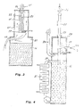
- figure 1 shows an apparatus for melting of metals in accordance with the invention.
- Figure 2 shows a combined apparatus for melting of metals and for molding and cooling of a molded metal rod.
- Figure 3 shows an apparatus for molding of melted metal accordin to the invention.
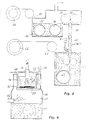
- Figure 4 shows an apparatus for stress-relieving anneal of a rod
- figure 5 shows an apparatus for annealing of a non-allergic creating metal wire
- figur 6 shows another apparatus for stress-relieving anneal of a wound ring of metal wire.
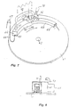
- Figure 7 shows an apparatus for soldering of a metal chain according to the invention
- figure 8 is a cross section along line VIII-VIII of figure 7.
- the most important feature of the invention is that optimum pure metals are used and that the total working of the metal or the metal alloy is made so that no impurities are added during the working.
- jewel metals are in a first hand considered gold, silver, platina, palladium, rodium and other precious metals which may have been alloyed to each other or to alloy metals, in the first hand copper, zinc or tin but even aluminum, nickel and chrome. All alloy metals must be optimum pure and not in any way treated in the surface. Previously it was considered wanted or necessary that some types of heavy metals or similar material was added, for instance cadmium, lead, mercury, bismuth, antimony or cobolt.
- a suitable reduction agent in the form of a melting powder having an excellent property to force impurities out of the melted metal is a mixture of one part of potassium carbonate and 1.5 part of waterfree sodium carbonate.
- the slag layer thereby obtained also has the important purpose of preventing the access of air during the continued melting and cooling of metals.
- the melting together of the metals is made without any access of air, for instance in that a protective gas is continuously blown over the metal surface or that the melting is made by means of a flame which covers the entire surface and prevents the access of air. It is also possible to make use of the supply of protective gas and a covering flame.
- FIG 1 shows a crucible, especially a grafite crucible 1 having a lid 2 which is connected to a positive pole of current and having a bottom 3, which is connected to a negative pole of current.
- the crucible also may have an alternative current heating.
- the lid is closed by a stopper 4.
- a gas inlet 5 for protective gas and an outlet 6 for the protective gas In the lid or any other high position of the crucible there is also a gas inlet 5 for protective gas and an outlet 6 for the protective gas.
- a spout 7 in the lid which is closed by a spout stopper 8.
- In the crucible there is melted metal 9, which is heated electrically in that the current is brought to pass the grafite crucible from the positive lid 2 to the negative bottom 3.
- a suitable protective gas is obtained by burning waterfree acetylene gas or methane gas together with a controlled amount of waterfree pure oxygene in a combustion chamber 10.
- waterfree compressed air may be used. In this case he purity is slightly less and the heating follows more slowly depending on the cooling effect of the nitorgene gas component.
- the combustion is made with deficit of oxygene and the amount of oxygene is controlled so that the exhaust gas outlet at the gas outlet 6 contains un-combusted gases which may be ligthened, whereby a very thin blue coloured flame 11 appears.
- an atmosphere is created inside the combustion chamber and thereby also inside the gas volyme 12 above the surface of the melted metal 9, which volyme 12 absolutely free from oxygene, hydrogene or nitrogene gas.
- a productive gas of the above mentioned type can be used in all conditions during heat treatment of the metal object.
- the entire gas volume 12 of the crucible is perculated by the combustible exhaust gas from the combustion chamber 10 and the surface of the melted metal 9 is continuously spray washed with the said combustible exhaust gas. If on the contrary, the melting and the molding is made under vacuum all gas volumes firstly must be perculated by the combustible exhaust gas or protective gas, and not until the gas volyme has been perculated the volumes are subjected to vacuum.
- the melted metal or the metal alloy is molded to blanks without access of air, preferably under protective gas underneath the reducing slag layer for preventing oxidization.
- the molding of melted metal can be made in a mould, for instance a tube which is preferably rubbed with oil. The entire tube is surrounded by a flame or a protective gas which prevents the access of air.
- the melted metal evaporizes the oil on the walls of the tube, and also the oil gases thereby obtained provide a protective gas which conributes to protecting of the metal against access of air.
- oil for the mold tube peviously was used animal oils like lard fat etc. Also caster-oil or asphalt based oils have been used.
- the castor oil however, quickly turns rancid, and aspahlt based oils in turn, give harmful effects.
- a paraffine based oil which gives a well protecting, inert protective gas layer and which has no harmful influence on the continued treatment of the metal.
- a blank molded under paraffine based oil exhaust gases gets very good soldering joints during the continued treatment.
- Figure 2 shows a combined apparatus for melting and molding of metal under vacuum.
- the apparatus comprises a carrier 13 which at the bottom contains a cooling liquid 14 of the previously described type and which above the level of the cooling liquid carries a mold, for instance a mold tube 15, which at the top has an inlet 16 for protecting gas and at the bottom has a drop shutter 17 for letting the molding metal out.
- a mold tube 15 On top of the mold tube 15 a mold crucible of the same type as in figure 1 is placed.
- the mold crucible 1' in which the melted metal 9' is heated has a gas inlet 5' and a gas outlet 6' for the exhausted protective gas.
- the carrier 13 encloses the entire apparatus as an air sealed unit. Between the level of the cooling liquid 14 and the mold tube, there is an inlet 19 for combustion gas and oxygene which inside the carrier is combusted under deficit of oxygene thereby providing a protective gas.
- the protective gas perculates the entire carrier between the mold tube 15 and the carrier walls, and the protective gas also flows into the gas inlet 15 of the crucible 1' and out through the gas outlet 6' whereby the gas is lightened, whereby the week blue flame indicates the decifit of oxygene of the protective gas inside the apparatus.
- the crucible 1' When using the apparatus in figure 2, the crucible 1' is closed by means of the spout stopper 18' and metal and possible reduction agent is filled into the crucible. Combustible gas and oxygene is supplied through the gas inlet 19, and the protective gas is allowed to force the air out of the equipment.
- the lid 2' and the bottom 3' of the crucible 1' are connected to a source of power, whereby the metal and the reduction agent are melted.
- the drop shutter 17 is kept open and protective gas, which may be supplied form a branch conduit 20 to the protective gas chamber 21 is blown through the gas inlet to the mold tube 15, whereby the protective gas forces the air out of the tube.
- the channel of the mold tube 15 should be conicly widened in the direction downwards in order to facilitate the releasing of the mold blank from the mold 15.
- the drop shutter 17 When the metal 9' is melted the drop shutter 17 is closed, and the gas inlet 16 now is connected to a vacuum pump which sucks the protective gas out of the mold chamber 22 of the mold tube 15.
- the pouring spout 18 of the crucible is lifted and the melted metal 9' is allowed to flow down into the mold chamber 22, in which the melted metal rapidly becomes solidified.
- the drop shutter 17 is reopened and the mold tube 15 together with the mold blank is let down as indicated with the dotted line 23. After some distance of free fall the mold 15 hits a stop bar as shown in figure 2. Thereby the mold gets a shock so that the blank 23 is released and drops down in the cooling liquid 14. After the molded bar has been cooled it is ready to be taken out for possible further working.
- Figure 3 shows an alternative equipment for molding of metal, which preferably may be combined with the crucible shown in figure 1.
- the upper portion of the carrier 13 has an opening 24 through which protective gas flows from the protective gas chamber 21 and through the annular channel between the mold tube 15 and the carrier 13'.
- the protective gas leaving the opening 24 is lightened thereby giving the above mentioned thin blue flame 11' which indicates deficit of oxygene of the protective gas inside the carrier 13'.
- the crucible in figure 1 is tilted so that the spout 7 with the spout stopper 8 comes within the area of the gas flame 11', whereby air is prevented to come into contact with the molten metal. Molding and cooling otherwise is made as explained in connection to figure 2.
- FIG 4 an apparatus for stress-relieving anneal is shown of a bar 25 in an apparatus which in substantial parts coincides with the apparatus of figure 3.
- the bar 25 is carried in a vertically reciprocatable hook 26 and can be let down through an opening in a closed refractory furnace 28, in which the form and size of the opening 27 closely conicides with the form and size of the bar 25.
- the furnace 28 has one or more inlets 19 for combustible gas and oxygene at some central portion of the furnace, and in the lower part of the furnace there is a chimney or an outlet 29 for exiting protective gas.
- cooling liquid 14 is provided which liquid preferably over a branch conduit 30 and a heat exchanger 31 is cooled and recirculated. Hot cooling liquid is removed at the upper portion of the cooling liquid chamber and chilled liquid enters at the bottom of the chamber.
- the bar 25 is stress-relieving annealed and is successively let down in the cooling liquid 14.
- Figure 5 shows an apparatus for stress-relieving anneal of a wire without access of air.
- a wire 33 passes over a pully and enters a de-ionized water bath 34 in which the wire moves at last in two turns over an idle running contact roller 35 of copper, grafite or carbon or similar material.
- a driving roller 36 the wire is fed from the water bath and into the area of a syncronously driven guide roller 37 and an idle running roller 38 which are provided at the upper portion of a protective gas channel 39.
- the protective gas channel 39 there is an inlet 40 for combustible gas and oxygene, and at the lower part of the protective gas channel there is also connected another waterbath 41 for de-ionized water and having a purity, which like the purity of the water bath 34 is less than 0.1 ⁇ s
- the wire is driven between two guide rollers and at last two turns round a driving, speed controlling contact roller 42 of copper, grafite, carbon or a similar alternative material. From the contact roller 42 the wire is fed to a winding roller 44 over a pully 43.
- a current is fed.
- the current heats the wire to a suitable temperature for stress-releaving anneal, and the annealing is made while the wire passes through the protective gas channel 39 in which the protective gas entering the gas inlet 40 prevents the access of air.
- a main gas outlet B is provided at or adjacent the surface of the cooling bath, and only a minor portion of the exhaust gas is allowed to pass the channel 39 and to leave through the top outlet A.
- Figure 6 shows an alternative embodiment for stress-releaving anneal of a ring 45 of wound wire.
- the annealing is made in an open container 46 of a refractory material which at the top is formed with an annular tube 47 having an inlet 48 for protective gas.
- the circular tube 47 is formed with a downwards extending annular wall 49 providing a downwards directed curtain of protective gas entering the container 46.
- the container 46 is mounted in an outer container 50 under gas sealed conditions. In the bottom of the outer container 50 there is a cooling bath 51 and on a level above the surface of the cooling bath there is an inlet 52 for protective gas.
- the inner container 46 is formed with a drop shutter 53 by which the wire ring 45 is supported.
- the heating of the wire ring to stress-relieving anneal temperature is providing by a manually or mechanically controlled burner 54 which is facing the bottom of the container 46 and the wire ring 45.
- a manually or mechanically controlled burner 54 which is facing the bottom of the container 46 and the wire ring 45.
- protective gas leaves through a gas outlet 56 at the top of the outer container 50, and the protective gas together with a combustible gas from the inner part of the inner container 46 leaves in the direction upwards through the open container thereby preventing air from entering the container.
- the exhaust gas from the outlet 56 may be guided to the inlet 48 and may be used for the protective gas curtain from the gas ring 47.
- the blank provided according to the invention may be a bar, a wire or any other object, and said blank is cold worked to any wanted shape.
- the col working does not necessitate any particular handling and is made in the conventional way in the air.
- the continued treatment involves soldering of the blank, and for facilitating the continued handling and to prevent joints from opening when subjected to soldering heating the blank is stress-relieving annealed in the above described way.
- the stress-relieving anneal is made without access of air and without contact with any external substances. It should be noted that the stress-relieving anneal previously was made in a heated salt bath, but according to the invention it is important that the stress-releaving anneal is made without any contact with such salts.
- solder When soldering the cold worked and stress-relieving annealed object, for instance a chain, solder is applied in the joints of the chain and the chain is heated until the solder melts and interconnect the ends of the joint.
- Soldering can be made by means of the apparatus shown in figure 6, whereby the wire ring 45 is substituted by the object or objects to be soldered, and immediately after soldering temperature has been reached and the solder has molted in the joints the drop shutter 53 is opened and the soldered objects are let down in the cooling bath 51. Also in connection to soldering it is important that the air is prevented from getting into contact with the hot objects, and this is effectively prevented in the apparatus according to figure 1. In this apparatus it is possible to provide a discontinuous soldering of long chains, whereby the chain is successively and stepwise fed down in the heating chamber under the gas curtain 49 and the burner 54, and correspondingly the chain is stepwise let down in the cooling bath 51.
- the apparatus comprises a movable table like for instance a circular table 61 which rotates at a controlled speed around a shaft 62. At or adjacent the periphery of the table there is a heating channel 63 which is substantially sealed towards the table 61. At the inlet end 64 the heating channel 63 has a small opening 65 for entering of an object to be stress-relieving annealed or to be soldered for instance a chain 66, which over a pully 67 is continuously fed down on the table. At the outlet end the heating channel 63 is directly connected to a cooling channel 68, which preferably has less dimensions than the heating channel 63.
- the outlet hole at the outlet end of the heating channel 63 (not shown) is like the inlet hole 65 of small dimension for reasons which will be explained in the following.
- the cooling channel 68 should have such length that the treated objects, for instance the chain 66, has a temperature when leaving the cooling channel 68 which is substantially less than the oxidization temperature.
- the outlet hole 69 of the cooling channel 68 is large.
- the heating channel 63 has two tube connections, viz. a connection 70 at the outlet end of the heating channel 68 for supply of combustible gas and some amount of oxygene and a second connection 71 at the inlet end of the heating channel 63 for removal of exhaust gases.
- the exhaust gas connection 71 is directly connected to a connection 73 at the inlet end of the cooling channel 68.
- the exhaust gases from the exhaust gas outlet 71 are thereby directly fed to an exhaust gas inlet of the cooling channel, while being successively cooled the exhaust gases pass through the cooling channel 68 and leave through the large outlet hole 69.
- the heating channel 63 has a small inlet opening 65 and a small outlet opening, the largest portion of the exhaust gases are transmitted from the exhaust gas outlet 71 from the heating channel 63 to the gas cooling inlet 73 of the cooling channel 68.
- a stretching of the chain may cause the links to open and for avoiding such stretching of the chain
- a pusher roller 74 is provided at the inlet end of the cooling channel 68.
- the pusher roller 74 extends through the wall of the cooling channel 68 and is placed so as to be in some contact with the chain.
- the pusher roller 74 rotates with a peripheral speed which is slightly less than the moving speed of the chain on the table 61, and the roller 74 thereby pushes the links into each other.
- the pusher roller 74 is cooled, for instance by a fan 75 and the pusher roller thereby also contributes to a quick cooling of the chain 66.
- the exhaust gases from the inlet 70 for combustible gases and oxygene are successively cooled during the passage through the heating channel 63, through the connecion conduit 72 and through the cooling channel 68, and the chain is successively cooled by said gases while passing through the cooling channel.
- the exhaust gases provide an effective protective gas preventing the access of air both to the heating channel 63 and to the cooling channel 68.
- a fluxing material may be let into the soldering chamber together with the protective gas or the heating gas.
- the soldering of course also can be made in that the chain is moved in an atmosphere on protective gas and in that a soldering flame is directed to the chain while passing the said flame.
- the said plate is surrounded by the protective gas which prevents the air from getting into contact with the chain and thereby prevents the metal from oxidizing and for assimilating impurities which later may cause allergic affections.
- the metal gets in contact with strange substances like waxes and the like during polishing.
- the surface cleaning and the polishing rather can be carried out in vibrating rubber containers filled with small parts of steel having a suitable shape and size for providing a mecanical cleaning and polishing of the manufactured product.
- the two liquids can be used for coarse polishing de-ionized water or pure alcohol or a mixture o the two liquids can be used. Both liquids must have a purity of at least 0.1 ⁇ s/cm2, and there may be an addition of powdered optimum pure chalk or a similar material.
- a final surface covering may be provided by galvanic plating based solely on a technique using potassium cyanide.
- the chemicals of the potassium cyanide bath likewise must be made of optimum pure metal salts and must be made of optimum pure metal salts and must be continuously filtered and purified by means of carbon filter or a corresponding purifying means, and the bath must be protected against any addition of foreign substances in that the bath is hermetically closed. It is not allowed to add any potassium chloride of any type to the bath, nor any acids or acid treated products may be added.
- the galvanic process must under no circumstances be speeded up by a too large flow of current. In case there is a risk that a dialyzis starts which in turn starts production of oxygene and hydrogene gases this must be avoided.
- the product is once again fine polished in a vibrating equipment as previously explained.
- Any surface polishing should be made in a bath which prevents the air from entering. In all surface polishing there is a friction heating, whereby the ability of the metal to assimilate impurities is increased.
- the pure bath prevents such assimilation of impurities.
Landscapes
- Engineering & Computer Science (AREA)
- Chemical & Material Sciences (AREA)
- Mechanical Engineering (AREA)
- Materials Engineering (AREA)
- Metallurgy (AREA)
- Organic Chemistry (AREA)
- General Engineering & Computer Science (AREA)
- Physics & Mathematics (AREA)
- Thermal Sciences (AREA)
- Crystallography & Structural Chemistry (AREA)
- Health & Medical Sciences (AREA)
- Clinical Laboratory Science (AREA)
- Adornments (AREA)
- Pharmaceuticals Containing Other Organic And Inorganic Compounds (AREA)
- Eyeglasses (AREA)
- Manufacture And Refinement Of Metals (AREA)
- Non-Insulated Conductors (AREA)
- Cosmetics (AREA)
- Saccharide Compounds (AREA)
- Peptides Or Proteins (AREA)
- Electroplating And Plating Baths Therefor (AREA)
- Heat Treatment Of Strip Materials And Filament Materials (AREA)
- Coating With Molten Metal (AREA)
- Physical Vapour Deposition (AREA)
- Heat Treatment Of Articles (AREA)
- Medicines That Contain Protein Lipid Enzymes And Other Medicines (AREA)
- Medicines Containing Material From Animals Or Micro-Organisms (AREA)
Applications Claiming Priority (3)
| Application Number | Priority Date | Filing Date | Title |
|---|---|---|---|
| SE8206158 | 1982-10-29 | ||
| SE8206158A SE8206158L (sv) | 1982-10-29 | 1982-10-29 | Forfarande och anordning for framstellning av allergifria edelmetallforemal |
| EP83903600A EP0124574B1 (de) | 1982-10-29 | 1983-10-28 | Verfahren und vorrichtung zur herstellung keine allergie erregender edelmetallgegenstände |
Related Parent Applications (1)
| Application Number | Title | Priority Date | Filing Date |
|---|---|---|---|
| EP83903600.1 Division | 1983-10-28 |
Publications (3)
| Publication Number | Publication Date |
|---|---|
| EP0241582A2 true EP0241582A2 (de) | 1987-10-21 |
| EP0241582A3 EP0241582A3 (en) | 1990-01-31 |
| EP0241582B1 EP0241582B1 (de) | 1994-08-24 |
Family
ID=20348398
Family Applications (2)
| Application Number | Title | Priority Date | Filing Date |
|---|---|---|---|
| EP86113177A Expired - Lifetime EP0241582B1 (de) | 1982-10-29 | 1983-10-28 | Verfahren zur Herstellung von Edelmetall-Gegenständen, die keine allergischen Reaktionen hervorrufen. |
| EP83903600A Expired - Lifetime EP0124574B1 (de) | 1982-10-29 | 1983-10-28 | Verfahren und vorrichtung zur herstellung keine allergie erregender edelmetallgegenstände |
Family Applications After (1)
| Application Number | Title | Priority Date | Filing Date |
|---|---|---|---|
| EP83903600A Expired - Lifetime EP0124574B1 (de) | 1982-10-29 | 1983-10-28 | Verfahren und vorrichtung zur herstellung keine allergie erregender edelmetallgegenstände |
Country Status (22)
| Country | Link |
|---|---|
| US (2) | US4902342A (de) |
| EP (2) | EP0241582B1 (de) |
| JP (1) | JPS59501913A (de) |
| KR (1) | KR910009870B1 (de) |
| AT (2) | ATE110421T1 (de) |
| AU (2) | AU567701B2 (de) |
| CA (1) | CA1222636A (de) |
| CZ (1) | CZ281582B6 (de) |
| DD (1) | DD218394A5 (de) |
| DE (2) | DE3382325D1 (de) |
| DK (1) | DK167287B1 (de) |
| ES (1) | ES8504268A1 (de) |
| FI (1) | FI74741C (de) |
| HU (1) | HUT38402A (de) |
| IT (1) | IT1197736B (de) |
| MX (2) | MX164073B (de) |
| NO (1) | NO164358C (de) |
| PT (1) | PT77560B (de) |
| SE (1) | SE8206158L (de) |
| SK (1) | SK278968B6 (de) |
| WO (1) | WO1984001788A1 (de) |
| ZA (1) | ZA838048B (de) |
Families Citing this family (26)
| Publication number | Priority date | Publication date | Assignee | Title |
|---|---|---|---|---|
| SE8206158L (sv) * | 1982-10-29 | 1984-04-30 | Hans G Wahlbeck | Forfarande och anordning for framstellning av allergifria edelmetallforemal |
| US5226946A (en) * | 1992-05-29 | 1993-07-13 | Howmet Corporation | Vacuum melting/casting method to reduce inclusions |
| DE69317079T2 (de) * | 1992-07-20 | 1998-08-13 | Koninkl Philips Electronics Nv | Verfahren zum Herstellen einer Formplatte und danach hergestellte Formplatten |
| WO1999014387A1 (en) * | 1997-09-12 | 1999-03-25 | Engelhard-Clal Uk Ltd. | Process for manufacturing precious metal artefacts |
| TW432020B (en) * | 1998-04-27 | 2001-05-01 | Nh Technoglass Co | Lining material for glass melting furnace, glass melting furnace, production of glass product and purification of lining material for glass melting furnace |
| DE19838888C2 (de) * | 1998-08-27 | 2001-07-19 | Hafner C Gmbh & Co | Verfahren zum Herstellen eines Formkörpers aus Rhodium |
| US6692588B1 (en) * | 1999-07-12 | 2004-02-17 | Nutool, Inc. | Method and apparatus for simultaneously cleaning and annealing a workpiece |
| SE517576C2 (sv) * | 2000-10-04 | 2002-06-18 | Hans Gustav Erik Wahlbeck | Arrangemang för en kedjematning |
| SE519401C2 (sv) * | 2000-10-25 | 2003-02-25 | Hans Gustav Erik Wahlbeck | Arrangemang för att avlägsna slaggprodukter från kedjor |
| SE517515C2 (sv) * | 2000-11-07 | 2002-06-11 | Hans Gustav Erik Wahlbeck | Länksvetsande arrangemang |
| SE517724C2 (sv) * | 2000-11-07 | 2002-07-09 | Hans Gustav Erik Wahlbeck | Länkkylande arrangemang vid kedjetillverkning |
| SE518022C2 (sv) * | 2000-12-11 | 2002-08-20 | Hans Gustav Erik Wahlbeck | Anordning för tryckreglering av avgaser vid svetsning eller lödning av kedjor |
| SE518054C2 (sv) * | 2000-12-29 | 2002-08-20 | Hans Gustav Erik Wahlbeck | System för att bilda en kedja |
| SE518477C2 (sv) * | 2001-02-22 | 2002-10-15 | Hans Gustav Erik Wahlbeck | Hållare för ett arrangemang ingående i en produktionslinje för kedjetillverkning |
| TW570851B (en) * | 2001-03-28 | 2004-01-11 | Phild Co Ltd | Method and device for producing metal powder |
| TW558471B (en) * | 2001-03-28 | 2003-10-21 | Phild Co Ltd | Method and device for manufacturing metallic particulates and manufactured metallic particulates |
| SE0103810L (sv) * | 2001-11-15 | 2003-05-16 | Hans Gustav Erik Wahlbeck | Operatörsanpassat system |
| JP2005289776A (ja) * | 2004-04-05 | 2005-10-20 | Canon Inc | 結晶製造方法および結晶製造装置 |
| EP1598435A1 (de) * | 2004-05-21 | 2005-11-23 | Leg.Or S.r.l | Verfahren zur Verringerung der Allergenizität von Metallwaren aus Allergen-Elemente enthaltenden Legierungen |
| US20070030880A1 (en) * | 2005-08-04 | 2007-02-08 | Kaz, Incorporated | Gold tip thermometer |
| ES2304218B1 (es) | 2007-03-12 | 2009-09-14 | Endesa Generacion, S.A | Procedimiento para estabilizar yeso. |
| WO2009126095A1 (en) * | 2008-04-09 | 2009-10-15 | Biopm Ab | Method of producing precious metal alloy objects |
| US20120083007A1 (en) * | 2010-10-01 | 2012-04-05 | Nadeau Kari C | Basophil Activation Based Allergy Diagnostic Test |
| CN102899514B (zh) * | 2012-09-06 | 2014-03-26 | 深圳市帕玛精品制造有限公司 | 一种贵金属合金熔炼方法 |
| US9802233B2 (en) | 2014-05-01 | 2017-10-31 | Praxair S. T. Technology, Inc. | Gold evaporative sources with reduced contaminants and methods for making the same |
| EP3020835B1 (de) * | 2014-11-17 | 2021-04-21 | Omega SA | Uhr, Schmuckstück oder edler Schmuck, umfassend eine Komponente aus einer Legierung auf Palladiumbasis |
Family Cites Families (27)
| Publication number | Priority date | Publication date | Assignee | Title |
|---|---|---|---|---|
| DE150470C (de) * | ||||
| US698769A (en) * | 1899-07-17 | 1902-04-29 | Elias H Bottum | Process of preventing oxidation of molten metals. |
| US1557431A (en) * | 1925-09-04 | 1925-10-13 | Victor D Davignon | Gold alloy and method of making the same |
| US1838015A (en) * | 1925-12-01 | 1931-12-22 | Bbc Brown Boveri & Cie | Annealing apparatus |
| US2105312A (en) * | 1937-10-29 | 1938-01-11 | Sigmund Cohn | Palladium nickel ruthenium alloy |
| US2429970A (en) * | 1944-01-11 | 1947-10-28 | Du Pont | Silver plating |
| FR975792A (fr) * | 1947-12-06 | 1951-03-09 | Mond Nickel Co Ltd | Perfectionnements aux procédés de fusion par induction du palladium et des alliages de palladium |
| DE970605C (de) * | 1950-07-21 | 1958-10-09 | Telegraph Constr & Maintenance | Verfahren und Vorrichtung zum fortlaufenden Gluehen von Metallbaendern und Draehten unter Luftabschluss |
| GB689553A (en) * | 1950-09-21 | 1953-04-01 | Mond Nickel Co Ltd | Improvements relating to the production of castings of palladium and alloys thereof |
| DE841063C (de) * | 1951-03-29 | 1952-06-13 | Benno Schilde Maschb Ag | Blankgluehverfahren |
| NL273924A (de) * | 1961-01-24 | |||
| GB949217A (en) * | 1959-06-17 | 1964-02-12 | Renault | Improvements in or relating to independent front wheel suspension systems of vehicles |
| US3022162A (en) * | 1960-07-25 | 1962-02-20 | Ralph G Donnelly | Brazing alloys |
| GB920978A (en) * | 1960-10-24 | 1963-03-13 | Westinghouse Brake & Signal | Process for producing a gold-silver antimony alloy |
| US3819366A (en) * | 1969-03-21 | 1974-06-25 | Aurium Res Corp | Dental alloy |
| US3613209A (en) * | 1969-12-09 | 1971-10-19 | Piquerez Sa Ervin | Process for manufacturing gold alloy watch casings |
| SE347020B (de) * | 1970-06-15 | 1972-07-24 | Wahlbeck Med Fa B Wahlbeck H | |
| AT301892B (de) * | 1970-08-17 | 1972-09-25 | Hans Hell Hoeflinger | Verfahren zum Verhindern der Sudhautbildung (Oxydation) bei der Goldwarenfabrikation |
| FR2116861A5 (fr) * | 1970-12-10 | 1972-07-21 | Rech Magnetiques D Et | Procede et dispositif de fabrication d'alliages d'elements de transition et de metaux du groupe des terres rares destinees a la production de materiaux pour aimants permanents |
| DE2154517A1 (de) * | 1971-11-03 | 1973-05-10 | Owens Corning Fiberglass Corp | Legierung |
| DE2450291A1 (de) * | 1974-10-23 | 1976-05-06 | Friedrich Von Dipl Stutterheim | Verfahren zur kontinuierlichen elektrolytischen metallbeschichtung von draehten, baendern, ketten und netzbaendern |
| SE393820B (sv) * | 1976-06-14 | 1977-05-23 | Degussa | Hard kopparfri dentalguldlegering |
| US4180700A (en) * | 1978-03-13 | 1979-12-25 | Medtronic, Inc. | Alloy composition and brazing therewith, particularly for _ceramic-metal seals in electrical feedthroughs |
| US4236941A (en) * | 1979-01-22 | 1980-12-02 | General Motors Corporation | Method of producing heat treatment atmosphere |
| JPS5638419A (en) * | 1979-09-05 | 1981-04-13 | Kanto Yakin Kogyo Kk | Metal heating furnace with protective atmosphere |
| JPS58113332A (ja) * | 1981-12-14 | 1983-07-06 | Res Inst Electric Magnetic Alloys | 温度の広範囲にわたり電気抵抗の変化の小さい合金およびその製造方法 |
| SE8206158L (sv) * | 1982-10-29 | 1984-04-30 | Hans G Wahlbeck | Forfarande och anordning for framstellning av allergifria edelmetallforemal |
-
1982
- 1982-10-29 SE SE8206158A patent/SE8206158L/xx unknown
-
1983
- 1983-10-25 CA CA000439668A patent/CA1222636A/en not_active Expired
- 1983-10-25 MX MX199205A patent/MX164073B/es unknown
- 1983-10-25 MX MX017540A patent/MX173530B/es unknown
- 1983-10-27 ES ES527143A patent/ES8504268A1/es not_active Expired
- 1983-10-27 PT PT77560A patent/PT77560B/pt active IP Right Revival
- 1983-10-28 AU AU22032/83A patent/AU567701B2/en not_active Expired
- 1983-10-28 IT IT49249/83A patent/IT1197736B/it active
- 1983-10-28 DE DE8383903600T patent/DE3382325D1/de not_active Expired - Lifetime
- 1983-10-28 WO PCT/SE1983/000371 patent/WO1984001788A1/en not_active Ceased
- 1983-10-28 AT AT86113177T patent/ATE110421T1/de not_active IP Right Cessation
- 1983-10-28 EP EP86113177A patent/EP0241582B1/de not_active Expired - Lifetime
- 1983-10-28 JP JP83503544A patent/JPS59501913A/ja active Pending
- 1983-10-28 DD DD83256093A patent/DD218394A5/de not_active IP Right Cessation
- 1983-10-28 EP EP83903600A patent/EP0124574B1/de not_active Expired - Lifetime
- 1983-10-28 ZA ZA838048A patent/ZA838048B/xx unknown
- 1983-10-28 HU HU83113A patent/HUT38402A/hu unknown
- 1983-10-28 SK SK7968-83A patent/SK278968B6/sk unknown
- 1983-10-28 AT AT83903600T patent/ATE64761T1/de not_active IP Right Cessation
- 1983-10-28 DE DE3382756T patent/DE3382756T2/de not_active Expired - Lifetime
- 1983-10-28 CZ CS837968A patent/CZ281582B6/cs not_active IP Right Cessation
- 1983-10-29 KR KR1019830005144A patent/KR910009870B1/ko not_active Expired
-
1984
- 1984-06-27 FI FI842587A patent/FI74741C/fi not_active IP Right Cessation
- 1984-06-27 NO NO84842594A patent/NO164358C/no not_active IP Right Cessation
- 1984-06-28 DK DK316384A patent/DK167287B1/da not_active IP Right Cessation
-
1987
- 1987-09-21 US US07/099,661 patent/US4902342A/en not_active Expired - Fee Related
-
1988
- 1988-03-03 AU AU12613/88A patent/AU612136B2/en not_active Expired
-
1989
- 1989-08-21 US US07/396,324 patent/US4933023A/en not_active Expired - Lifetime
Also Published As
Similar Documents
| Publication | Publication Date | Title |
|---|---|---|
| EP0241582B1 (de) | Verfahren zur Herstellung von Edelmetall-Gegenständen, die keine allergischen Reaktionen hervorrufen. | |
| US6139652A (en) | Tarnish-resistant hardenable fine silver alloys | |
| US6841012B2 (en) | Anti-tarnish silver alloy | |
| FR2520858A1 (fr) | Procede de production d'articles de fours pour la fabrication de produits metalliques et ceramiques | |
| US20110030853A1 (en) | Method of producing precious metal alloy objects | |
| KR100432448B1 (ko) | 크롬, 니켈을 포함하는 알루미늄 합금판 제조방법 | |
| CN109652656A (zh) | 一种贵金属合金提纯富集工艺及氧化精炼炉 | |
| DE167915T1 (de) | Reaktor zur eisenherstellung. | |
| DE10142405A1 (de) | Vorrichtung und Verfahren zum Einleiten von Gasen in ein heißes Medium | |
| JP2007534836A (ja) | 銀の鎖の製造 | |
| KR970009511B1 (ko) | 동합금 소재의 제조방법 | |
| CN112289479B (zh) | 一种电磁屏蔽铝镁合金线缆及其生产工艺 | |
| CN109852817A (zh) | 一种富集金银合金的氧化炉 | |
| FR2694303A1 (fr) | Procédé d'élaboration d'alliages magnétiques doux à très haute perméabilité et alliages en résultant. | |
| DE1533095C (de) | Verfahren zur Feuerraffination von Kupferschmelzen | |
| DE2059235B2 (de) | Verfahren zur Gewinnung von Feinsilber mittels eines Treibprozesses | |
| Lopukhov | Cleaning the steel scrap from admixtures of nonferrous metals | |
| CZ117U1 (cs) | Zachlazovací těleso |
Legal Events
| Date | Code | Title | Description |
|---|---|---|---|
| PUAI | Public reference made under article 153(3) epc to a published international application that has entered the european phase |
Free format text: ORIGINAL CODE: 0009012 |
|
| AC | Divisional application: reference to earlier application |
Ref document number: 124574 Country of ref document: EP |
|
| AK | Designated contracting states |
Kind code of ref document: A2 Designated state(s): AT BE CH DE FR GB LI NL |
|
| PUAL | Search report despatched |
Free format text: ORIGINAL CODE: 0009013 |
|
| AK | Designated contracting states |
Kind code of ref document: A3 Designated state(s): AT BE CH DE FR GB LI NL |
|
| 17P | Request for examination filed |
Effective date: 19900723 |
|
| 17Q | First examination report despatched |
Effective date: 19921002 |
|
| GRAA | (expected) grant |
Free format text: ORIGINAL CODE: 0009210 |
|
| AC | Divisional application: reference to earlier application |
Ref document number: 124574 Country of ref document: EP |
|
| AK | Designated contracting states |
Kind code of ref document: B1 Designated state(s): AT BE CH DE FR GB LI NL |
|
| REF | Corresponds to: |
Ref document number: 110421 Country of ref document: AT Date of ref document: 19940915 Kind code of ref document: T |
|
| REF | Corresponds to: |
Ref document number: 3382756 Country of ref document: DE Date of ref document: 19940929 |
|
| ET | Fr: translation filed | ||
| PLBE | No opposition filed within time limit |
Free format text: ORIGINAL CODE: 0009261 |
|
| STAA | Information on the status of an ep patent application or granted ep patent |
Free format text: STATUS: NO OPPOSITION FILED WITHIN TIME LIMIT |
|
| 26N | No opposition filed | ||
| REG | Reference to a national code |
Ref country code: GB Ref legal event code: IF02 |
|
| PGFP | Annual fee paid to national office [announced via postgrant information from national office to epo] |
Ref country code: FR Payment date: 20021008 Year of fee payment: 20 |
|
| PGFP | Annual fee paid to national office [announced via postgrant information from national office to epo] |
Ref country code: AT Payment date: 20021011 Year of fee payment: 20 |
|
| PGFP | Annual fee paid to national office [announced via postgrant information from national office to epo] |
Ref country code: GB Payment date: 20021023 Year of fee payment: 20 |
|
| PGFP | Annual fee paid to national office [announced via postgrant information from national office to epo] |
Ref country code: NL Payment date: 20021031 Year of fee payment: 20 Ref country code: DE Payment date: 20021031 Year of fee payment: 20 |
|
| PGFP | Annual fee paid to national office [announced via postgrant information from national office to epo] |
Ref country code: CH Payment date: 20021101 Year of fee payment: 20 |
|
| PGFP | Annual fee paid to national office [announced via postgrant information from national office to epo] |
Ref country code: BE Payment date: 20021219 Year of fee payment: 20 |
|
| PG25 | Lapsed in a contracting state [announced via postgrant information from national office to epo] |
Ref country code: LI Free format text: LAPSE BECAUSE OF EXPIRATION OF PROTECTION Effective date: 20031027 Ref country code: GB Free format text: LAPSE BECAUSE OF EXPIRATION OF PROTECTION Effective date: 20031027 Ref country code: CH Free format text: LAPSE BECAUSE OF EXPIRATION OF PROTECTION Effective date: 20031027 |
|
| PG25 | Lapsed in a contracting state [announced via postgrant information from national office to epo] |
Ref country code: NL Free format text: LAPSE BECAUSE OF EXPIRATION OF PROTECTION Effective date: 20031028 Ref country code: AT Free format text: LAPSE BECAUSE OF EXPIRATION OF PROTECTION Effective date: 20031028 |
|
| BE20 | Be: patent expired |
Owner name: *WAHLBECK HANS G.E. Effective date: 20031028 |
|
| REG | Reference to a national code |
Ref country code: GB Ref legal event code: PE20 |
|
| REG | Reference to a national code |
Ref country code: CH Ref legal event code: PL |
|
| NLV7 | Nl: ceased due to reaching the maximum lifetime of a patent |
Effective date: 20031028 |