EP0240008B1 - Bandladung von magnetischem Aufnahme- und Wiedergabegerät - Google Patents
Bandladung von magnetischem Aufnahme- und Wiedergabegerät Download PDFInfo
- Publication number
- EP0240008B1 EP0240008B1 EP87104835A EP87104835A EP0240008B1 EP 0240008 B1 EP0240008 B1 EP 0240008B1 EP 87104835 A EP87104835 A EP 87104835A EP 87104835 A EP87104835 A EP 87104835A EP 0240008 B1 EP0240008 B1 EP 0240008B1
- Authority
- EP
- European Patent Office
- Prior art keywords
- pinch roller
- tape
- gear
- pole
- loading
- Prior art date
- Legal status (The legal status is an assumption and is not a legal conclusion. Google has not performed a legal analysis and makes no representation as to the accuracy of the status listed.)
- Expired - Lifetime
Links
- 230000007246 mechanism Effects 0.000 claims description 61
- 230000004044 response Effects 0.000 claims description 18
- 230000002441 reversible effect Effects 0.000 description 7
- 238000013459 approach Methods 0.000 description 5
- 230000002093 peripheral effect Effects 0.000 description 5
- 238000005549 size reduction Methods 0.000 description 5
- 208000016261 weight loss Diseases 0.000 description 5
- 239000013585 weight reducing agent Substances 0.000 description 5
- 230000008878 coupling Effects 0.000 description 4
- 238000010168 coupling process Methods 0.000 description 4
- 238000005859 coupling reaction Methods 0.000 description 4
- 238000000034 method Methods 0.000 description 4
- 230000008569 process Effects 0.000 description 4
- 230000009471 action Effects 0.000 description 3
- 230000009467 reduction Effects 0.000 description 3
- 238000006073 displacement reaction Methods 0.000 description 2
- 230000006872 improvement Effects 0.000 description 2
- 230000008859 change Effects 0.000 description 1
- 230000000881 depressing effect Effects 0.000 description 1
- 238000001514 detection method Methods 0.000 description 1
- 238000005516 engineering process Methods 0.000 description 1
- 208000023414 familial retinal arterial macroaneurysm Diseases 0.000 description 1
- 210000003746 feather Anatomy 0.000 description 1
- 238000000926 separation method Methods 0.000 description 1
Images


Classifications
-
- G—PHYSICS
- G11—INFORMATION STORAGE
- G11B—INFORMATION STORAGE BASED ON RELATIVE MOVEMENT BETWEEN RECORD CARRIER AND TRANSDUCER
- G11B15/00—Driving, starting or stopping record carriers of filamentary or web form; Driving both such record carriers and heads; Guiding such record carriers or containers therefor; Control thereof; Control of operating function
- G11B15/60—Guiding record carrier
-
- G—PHYSICS
- G11—INFORMATION STORAGE
- G11B—INFORMATION STORAGE BASED ON RELATIVE MOVEMENT BETWEEN RECORD CARRIER AND TRANSDUCER
- G11B15/00—Driving, starting or stopping record carriers of filamentary or web form; Driving both such record carriers and heads; Guiding such record carriers or containers therefor; Control thereof; Control of operating function
- G11B15/18—Driving; Starting; Stopping; Arrangements for control or regulation thereof
- G11B15/26—Driving record carriers by members acting directly or indirectly thereon
- G11B15/28—Driving record carriers by members acting directly or indirectly thereon through rollers driving by frictional contact with the record carrier, e.g. capstan; Multiple arrangements of capstans or drums coupled to means for controlling the speed of the drive; Multiple capstan systems alternately engageable with record carrier to provide reversal
- G11B15/29—Driving record carriers by members acting directly or indirectly thereon through rollers driving by frictional contact with the record carrier, e.g. capstan; Multiple arrangements of capstans or drums coupled to means for controlling the speed of the drive; Multiple capstan systems alternately engageable with record carrier to provide reversal through pinch-rollers or tape rolls
-
- G—PHYSICS
- G11—INFORMATION STORAGE
- G11B—INFORMATION STORAGE BASED ON RELATIVE MOVEMENT BETWEEN RECORD CARRIER AND TRANSDUCER
- G11B15/00—Driving, starting or stopping record carriers of filamentary or web form; Driving both such record carriers and heads; Guiding such record carriers or containers therefor; Control thereof; Control of operating function
- G11B15/60—Guiding record carrier
- G11B15/66—Threading; Loading; Automatic self-loading
- G11B15/665—Threading; Loading; Automatic self-loading by extracting loop of record carrier from container
- G11B15/6653—Threading; Loading; Automatic self-loading by extracting loop of record carrier from container to pull the record carrier against drum
- G11B15/6656—Threading; Loading; Automatic self-loading by extracting loop of record carrier from container to pull the record carrier against drum using two-sided extraction, i.e. "M-type"
Definitions
- the present invention relates generally to a magnetic recording/reproducing apparatus for recording or reproducing information with a magnetic tape being wrapped around a guide drum.
- a recording/reproducing apparatus comprising a guide drum having at least one recording or reproducing head and further comprising loading means having at least one vertical and one inclined pole for pulling out a tape from a tape cassette mounted on said recording/reproducing apparatus and for wrapping the tape around said guide drum.
- the loading means include a pole driving mechanism for driving the poles and a mechanism for causing a pinch roller to come into contact with a capstan so that the tape is interposed therebetween after the tape is wrapped around said guide drum.
- Said mechanism comprises a pinch roller cam driven in accordance with the movement of said pole driving mechanism, a pinch roller arm having said pinch roller and rotatably supported at one end portion and a link member coupled between said pinch roller cam and said pinch roller arm so that said pinch roller is directed to said capstan in response to the movement of said link member.
- the pinch roller is pressed against the capstan through the force of a loading ring by a pin provided on the latter and arranged to be engaged with a portion of the pinch roller cam.
- This arrangement causes a strong force between the pin on the loading ring and the portion of the pinch roller cam to supply sufficient pressing force to the pinch roller towards the capstan. Therefore the corresponding parts require great strengths so that they require massive designs which result in a heavy weight and a large dimension.
- VTR video tape recorders
- the standard track patterns of video signals to be recorded on the a magnetic tape are kept identical each other and further the length of magnetic tape in the tape path from the guide drum to the audio/control signal head (A/C head) are coincident with the standard length in terms of agreement of tracking servo control.
- a magnetic recording/reproducing apparatus is equipped with a guide drum having at least one recording or reproducing head and further equipped with loading means having at least one vertical pole and at least one inclined pole for pulling out a tape from a tape cassette mounted on said recording/reproducing apparatus and for wrapping the tape around said guide drum.
- Said loading means including a pole driving mechanism for driving the poles and a mechanism for causing a pinch roller to come into contact with a capstan so that the tape is interposed therebetween after the tape is wrapped around said guide drum.
- Said mechanism comprising a pinch roller cam driven in accordance with the movement of said pole driving mechanism, a pinch roller arm having said pinch roller rotatably supported at one end portion and a link member coupled between said pinch roller cam and said pinch roller arm so that said pinch roller is directed to said capstan in response to the movement of said link member.
- Said link member is the output link of a toggle mechanism, whereby a pressure spring means provided between a spring pin on said pinch roller cam and a fixed pin is the rocker link of the toggle mechanism, and said pinch roller cam with said spring pin acts as the crank at the joint of said link member and said pressure spring means, which are coupled at said spring pin.
- the toggle mechanism is spring means provided between a spring pin provided in the pinch roller cam and the link member so that the spring means causes the pinch roller to resiliently come into contact with the capstan. Furthermore, the spring means is arranged to apply its biasing force to the pinch roller cam so that the pole driving mechanism is pressed in the tape loading direction after the tape is wrapped around the guide drum.
- a small-sized tape cassette 1 is mounted in a magnetic recording/reproducing apparatus 10 (which will be described hereinafter) under the conditions that a supply reel hub 6 is fitted into a supply reel drive shaft of the apparatus 10, a tooth portion 7a on the peripheral surface of a take-up reel flange 7 is engaged with a drive gear (illustrated by numeral 100 in Fig. 2), vertical and inclinded loading poles, capstan and so on which will be described hereinafter relatively enter into recess portions 3a, 3b and 3c formed at the front side of a cassette housing 3, and a cover 4 is rotated and opened up to its horizontal position.
- a drive gear illustrated by numeral 100 in Fig. 2
- vertical and inclinded loading poles, capstan and so on which will be described hereinafter relatively enter into recess portions 3a, 3b and 3c formed at the front side of a cassette housing 3, and a cover 4 is rotated and opened up to its horizontal position.
- Figs. 1 through 5 shows a magnetic recording/reproducing apparatus according to a preferred embodiment of the present invention which is in the stop-mode state prior to mounting of the tape cassette 1.
- Fig. 1 is a schematic plan view showing the magentic recording/reproducing apparatus 10 excluding tape guide means such as a loading ring
- Fig. 2 is a right side view of the magnetic recording/reproducing apparatus of Fig. 1
- Fig. 3 is a plan view showing a pole base drive system including the loading ring
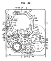
- Fig. 4A is a plan view showing a tape reel drive system including a capstan
- Fig. 4B is a side view showing a supply side tape loading and guide device
- Fig. 5 is a longitudinal sectional view of the reel drive system of Fig. 4A.
- the magentic recording/reproducing apparatus 10 substantially comprises a tape loading mechanism for pulling out a magnetic tape and for wrapping the pulled-out tape around a guide drum 11 through a predetermined angular range, a gear mechanism 16 constructed of a plurality of gear sets for driving the tape loading mechanism 15 and middle pole which reorients the travelling-tape surface and serves as a tape guide and a reel drive mechanism 17 for driving the tape reels of the tape cassette 1 and so on, these mechanisms being installed on a chassis base 14.
- a tape guide drum for example, wherein four video heads (rotary heads) are disposed at angular distance of 90-degrees from each other.
- the tape guide drum 11 comprises an upper drum 12 having the video heads and being rotatory, and a lower drum 13 fixedly secured to the chassis 14.
- the tape guide drum 11 is reduced in diameter to two-third of that of a conventional apparatus and a magnetic tape 2 is wrapped therearound ranging 270-degrees or more.
- the video heads are sequentially switched in units of a predetermined rotational angle as a tape-scanning angle so as to form a track pattern on the magnetic tape 2, which is identical to a standard track pattern of the current apparatus.
- the inclined angle of the guide drum 11 is about 10-degrees in the direction X-X with respect to its vertical axis, this is rather small in amount compared to a standard drum design, which means less height increase due to the inclination of the guide drum 11, and contributes to the overall size reduction of the apparatus 10.
- the lower drum 13 of the guide drum 11 is customerly secured to the chassis with an additional drum base interposed in between to produce designed drum inclination, but in this embodiment as shown in Figs. 6A and 6B a plurality of legs 13a1 to 13a4 having successively different lengths to correspond to the inclination angle and inclined direction of the guide drum 11 are unitarily constructed at the bottom portion of the lower drum 13, for keeping its profile low.
- the legs 13a1 to 13a4 are directly secured by screws 18 to the chassis base 14, resulting that the guide drum 11 is installed with a predetermined inclined angle with a great accuracy. This provides an extra space for other parts to be installed on the chassis base 14, further allowing size and weight reduction and in turn cost-reduction of the apparatus.
- the gear mechanism 16 and tape loading mechanism 15 for performing so-called parallel-loading are driven by a reversible single loading motor 19.
- the loading motor 19 for driving the gear mechanism 16 drives a terminal gear device 23 through a reduction gear as such a worm 20 of the motor shaft is engaged with a worm wheel 21 and a small gear 22 being in coaxial relation to the worm wheel 21 is engaged with a large gear 24 of the terminal gear device 23.
- a toothed portion 23a formed on the shaft of the terminal gear device 23 is arranged to rotationally drive a cam gear 26 integrally attached to a cam gear mechanism 25 for displacing a middle pole 39 which will be described hereinafter.
- a toothed portion formed on a shaft will be hereinafter referred to as shaft gear.
- a middle gear 27 of the terminal gear device 23 is engaged with an annular take-up loading gear (take-up gear) 28 of the tape loading mechanism 15 to rotate it counterclockwise during the tape loading around the guide drum 11 shown in Fig. 1.
- the take-up gear 28 drives slow (reduction-drive) a large gear 31 of a gear device 30 engaged therewith through an idle gear 29, whereby a small gear 32 integrally mounted to the large gear 31 is driven to clockwise reduction-drive a supply loading gear (supply gear) 33 of the tape loading mechanism 15 engaged therewith.
- the rotational driving force produced in response to positive rotation of the loading motor 19 is transferred through the worm wheel 21 and terminal gear device 23 to the take-up gear 28 to drive it at a predetermined speed, and the supply gear 33 is rotationally driven clockwise around the guide drum 11 shown in Fig. 1 in synchronism with the take-up gear 28 by means of a further reduction-drive of the gear device 30 effected through the idle gear 29 in response to the drive of the take-up gear 28 (in this case, the take-up gear 28 is rotated counterclockwise).
- the difference in rotational speed between the take-up gear 28 and the supply gear 33 results from the predetermined moving path lengths of respective pole bases which will be described hereinafter.
- An arm gear 34 is rotated counterclockwise about a pivot 40 with a pin 35 provided at one end portion thereof being engaged in a spiral cam groove 26a defined in the cam gear 26 and with a sector toothed portion 34a formed at the other end portion thereof being engaged with a shaft gear 37 of a pole arm 36 having a middle pole 39 at one end portion thereof.
- a lock arm 41 rotatable about the pivot 40 located thereon and urged counterclockwise by a torsion spring, not shown.
- the leaf spring 42 of the lock arm 41 is in contact with a small radius portion 43a of the cam 43 to release the middle pole 39 and during the tape loading that the arm gear 34 is rotated counterclockwise by a predetermined angle about the pivot 40, the shaft gear 37 engaged with the sector gear 34a is rotated clockwise whereby the pole arm 36 which is in the state shown in Fig. 16A intersects a guide rail 45 shown in Fig. 1 and the front of an A/C head AH and moves up to a normal position as shown in Fig. 16B.
- the leaf spring 42 of the lock arm 41 is relatively slidingly moved along the configuration of the cam 43. After the pole arm 36 has been rotated up to a predetermined stop position, the leaf spring 42 climbs up the large radius portion of the cam 43, and the lock arm 41 moves to lock the middle pole 39 as shown in Fig. 16B.
- the tape loading mechanism 15 for wrapping a magnetic tape around the outer peripheray of the guide drum 11 through abount 270-degrees substantially comprises the guide rail 45 fixedly secured onto the chassis base 14 and having a supply guide groove 44a and a take-up guide groove 44b longer than the supply guide groove 44a which are substantially in symmetrical positions with respect to the guide drum 11, the supply gear 33 disposed below the guide rail 45, and the take-up gear 28 disposed below the supply gear 33.
- the guide grooves 44a and 44b of the guide rail 45 include straight portions 44a1 and 44b1 disposed in front of the inserting opening of the tape cassette 1 and arc portions 44a2 and 44b2 coupled thereto. While the supply guide groove 44a is positioned above the chassis base 14, the take-up guide groove 44b is directed gradually toward below the chassis base 14 so as to form a three-dimentionally inclinded groove approximately starting from the center portion to the rear portion of the groove 44b in order to bring the magentic tape parallel to the surface of the inclined guide drum 11.
- a stopper portion 131 having at the upper and lower portions a U-shaped recess portion 129 and a V-shaped recess portion 130 accommodiating the vertical roller pole 58 as shown in Fig. 10.
- One end portion of the arc portion 44a2 of the supply guide groove 44a is divided into a groove 44a2' curved toward the guide drum 11 and a groove 44a2'' curved away from the groove 44a2' so as to form a Y-configuration. Also at one end portion of the groove 44a2'' as well as at the end portion of the take-up side guide groove 44b is provided a stopper portion, not shown, having at the upper and lower portions U-shaped and V-shaped recess portions for supporting the upper and lower portions of a vertical roller pole 46 of a pole base 48.
- the rotatable vertical roller pole (vertical pole) 46 and an inclined loading pole (inclined stationary pole) 47 are close each other and are mounted on a pole base 48 which has a forward leg 48a and a rearward leg 48b as shown in Fig. 4B both fitted into the supply guide groove 44a so that a moving position and orientation of the pole base 48 are controlled conforming to the shape of the supply guide groove 44a.
- a moving position and orientation of the pole base 48 are controlled conforming to the shape of the supply guide groove 44a.
- the forward leg 48a is guided into the curved groove 44a2'' and hence the rearward leg 48b swings to displace counterclockwise along the other curved groove 44a2' about the forward leg 48b resulting that the vertical pole 46 and the inclined pole 47 are aligned approximately with a center of the guide drum 11.
- the shaft of the vertical pole 46 is supported by the U-shaped and V-shaped recess portions of the stopper portion to position the pole base 48.
- Both the take-up gear 28 and supply gear 33, as shown in Figs. 3 and 7, are held in parallel each other with a plurality of guide toothed wheels 49 engaged therewith and are held by guide plates 50 so as to keep a predetermined spacing in the vertical direction.
- a guide plate 53 slidingly movable along slots 53a and 53b into which pins 51 and 52 mounted on the take-up gear 28 are inserted, and the relative movement of the guide plate 53 is limited by a tension spring 61 provided therebetween.
- a coupling bar 55 which can be displaced upwardly and downwardly about a shaft 54.
- Illustrated by numeral 57 is a take-up pole base rotatably supported by a shaft and having a vertical pole 58 and a inclined stationary pole 59 which are close each other, the take-up pole base 57 being moved along the guide rail 45 under guide of the lower portion of the vertical pole 58. At one end portion thereof is provided a tongue piece 57a entering into the stopper portion 131.
- the pole base 57 is, at the inclined stationary pole 59 side, pivotally coupled through a swing rod 60 to the coupling rod 55, and hence it is horizontally movable above the take-up gear 28 and also displaceable upwardly and downwardly by means of the operation of the coupling rod 55.
- pins 62a, 62b and 62c which are in predetermined distance to one another, and the pins 62a and 62b are located at the rear side of the guide plate 53 to drive a pinch roller cam 73 which will be described hereinafter and the remained pin 62c is located a position ahead of the pins 62a and 62b with respect to the rotational direction during the tape loading so as to lock an eject lever 65 shown in Fig. 3.
- the supply gear 33 is arranged as shown in Fig. 8B, and on the supply gear 33 is located a guide plate 64 having pins 65 and 66 which are slidingly movable along slots 33a and 33b, and the relative movement thereof is limited similarly by a tension spring 67 provided therebetween.
- a pin 68 On the guide plate 64 is planted a pin 68 and provided a coupling bar 70 rotatable about a shaft 69. The pin 68 sets up the rotatably supported vertical pole 46 and the inclined pole 47 in close relation to each other and locks the pole base 48 having a tongue piece 48a at its end portion.
- the disc-like pinch roller cam 73 for driving the pinch roller 71 to a predetermined position is rotatably supported by a shaft 72 fixed on the chassis 14 and in the peripheral portion thereof are defined first and second locking grooves 73a and 73b engageable with the pins 62b and 62a of the take-up gear 28 and a spring pin 75 is provided at a portion of the peripheral portion opposed to the locking grooves 73a and 73b with respect to the shaft 72. That is, the locking grooves 73a, 73b and the spring pin 75 are positioned to substantially form a triangle.
- the pin 62b planted on the take-up gear 28 is lockingly engaged with the first locking groove 73a of the pinch roller cam 73 supported by the shaft 72.
- the pinch roller cam 73 is rotated clockwise about the shaft 72 against a torsion spring (first resilient means) 74 provided between the spring pin 75 installed on the pinch roller cam 73 and a fixed pin 76.
- a pinch roller arm 78 having a pinch roller 71 is rotated counterclockwise about a shaft 77 through a link 81 connecting the spring pin 75 to a connecting pin 79, thereby moving close to a capstan 80.
- a toggle mechanism is made up of the pinch roller arm 78, the link 81 and the pinch roller cam 73.
- the pin 62b is released from the first locking groove 73a and the following pin 62a positioned afterwardly reaches the second locking groove 73b and locks it and the pinch roller cam 73 is further rotated compressing most the spring 74, and as a result the link 81 is further drawn in a direction D (Fig. 18C) and the pinch roller arm 78 is rotated counterclockwise about the shaft 77 to approach further the capstan 80.
- the pin 62a is moved as shown in Fig. 18C by rotation of the take-up gear 28, and the axis of the link 81 connecting the spring pin 75 and the connecting pin 79 exceeds the peak position and slightly displaced from the center of the shaft 72 to the loading termination position, whereby the link 81 is moved in the direction D against tension spring 82 provided between the link 81 and the pin 75 with it being guided by the pin 75 so that the the pinch roller 71 resiliently comes into pressure-contact with the capstan 80 (tape travelling state).
- the force F2 is generated in the rotational direction of the pinch roller cam 73 by means of the force F1 applied to the link 81 in the direction C, and the generated force F2 is applied to the take-up gear 28 in its rotational direction so that the pressure-contact force of the pole base 57 at the loading termination position is increased.
- the pinch roller 71 drawn in the direction D by means of the toggle mechanism comprising the pinch roller arm 78, link 81 and pinch roller cam 73, is certainly brought into resilient pressure contact with the capstan 80 by a predetermined force in connection with a small rotational force of the pinch roller cam 73, resulting in reduction of the load of the take-up gear 28 driving the pinch roller cam 73 concurrently with the reduction of the load of the loading motor 19.
- This causes the loading motor 19 to be small-sized and causes the driving parts to be reduced in weight.
- the biasing force of the torsion spring 74 is switched and applied to the pinch roller cam 73 in its rotational direction, and therefore the pinch roller cam 73 is biased clockwise by the spring (second resilient means) 82 and the spring 74, and in the loading termination state in which the loading motor 19 is stopped, the rotational force of the pinch roller cam 73 due to the biasing force is further applied through the pin 62a to the take-up gear 28 in the positively rotational direction so as to more certainly position the pole base 57.
- the play component generated on the mounting of the pinch roller 71 can be absorbed by the resilient action of the torsion spring 74.
- the reel drive mechanism 17 will hereinbelow be described in detail with reference to Figs. 1, 2, 4A and 5.
- the torque from the pulley 87 is transferred through a friction coupler (for example, felt), not shown, to an input gear 89 of the swing gear device 85 whereby a pair of planet gears 91 and 92 mounted on the arm 86 to be engaged with the input gear 89 performs friction coupled drive rotating in synchronism with each other.
- the large gear 95 is coupled through a friction plate 96 shown in Fig. 5 to another large gear 97 coaxially rotated therewith and having a diameter substantially equal thereto, and the large gear 97 is engaged with a small gear 99 which has integrally a small gear 100 thereabove and which is rotated about a shaft 98.
- the supply reel hub 6 is engaged with a supply reel drive shaft which will be described hereinafter and studs 101 and 102 enter into holes (not shown) provided to the tape cassette for lateral positioning whereby the small gear 100 is engaged with a toothed portion 7a formed on the take-up reel flage 7.
- a brake arm supported by a shaft 105, the brake arm 104 being biased clockwise by means of a torsion spring or the like, not shown, fitted with the shaft 105.
- a brake pad 106 at one end thereof comes into frictional contact with the drum portion 95a of the large gear 95 to brake it, if it is in the recording state and so on that the magnetic tape is travelled in the take-up direction by means of the pinch roller 71 and capstan 80, the brake pad 106 is separated from the drum portion 95a in connection with the movement of the pinch roller 71 so that the braking is released.
- the other planet gear 91 positioned at the left side of the swing gear device 85 is selectively engaged with a large gear 110, i.e., input flange, of a one-way clutch mechanism 109 within a supply reel disc device 108 supported by a shaft 107 installed on the chassis base 14.
- the large gear 110 is rotated together with a supply reel drive shaft 127 by means of a friction plate 125, and is coupled to a rotating body 112 by the encased one-way clutch mechanism 109 having rollers 111.
- the rotary body 112 is wound with a tension band 114 one end of which is connected to an arm lever 113, and another end anchored to the chassis base 14.
- the arm lever 113 is further coupled to a tension arm 119 which will be described hereinafter.
- the swing gear device 85 is rotationally moved in the direction indicated by F in Fig. 1 and the planet gear 92 is engaged with the right side large gear 95 to rotate it clockwise which in turn rotates the drive gear 100, thus as described before, the take-up reel is driven clockwise at its reel flange 7 by the drive gear 100 for taking up the magnetic tape 2.
- the supply reel drive shaft 127 directly coupled to the supply reel hub 6 of the tape cassette 1 is rotated clockwise, and hence the rollers 111 are squeezed into wedge-like recess portions of the rotating body 112 so that the rotating body 112 is rotated clockwise therewith.
- the tensile force of the tension band 114 is generated to apply a proper back tension to the magnetic tape whereby the magnetic tape is wound around the take-up reel.
- the tension arm 119 rotatably pivotally supported by a shaft 120 installed on the chassis base 14 is positioned such that one end portion thereof is engageable to be locked by the pole base 48 in the stop state and rotatably pivotally supports the arm lever 113 at the base portion 119a.
- the tension arm 119 is urged counterclockwise by biasing means, not shown, such as a torsion spring, when it is in the stop state shown in Fig. 1, it is locked by the supply pole base 48 returned to the rest position so as to stop against the force of the torsion spring.
- biasing means not shown, such as a torsion spring
- An impedance roller 115 is fixedly disposed between the full-tape-width erasing head 116 and the tension arm 119 to control the vibration of the travelling tape.
- a head base 123 on which the full-tape-width erasing head 116 is placed is rotatably supported by a shaft supporting the impedance roller 115 and biased by a spring, not shown, to provide a rotational force clockwise, and a lock portion 123a in one end portion of the head base 123 is positioned to allow a pin 124 of the tension arm 119 to be lockable.
- the pin 124 locks the lock portion 123a of the head base 123 having the full-tape-width erasing head 116 thereon and a clockwise rotational force is applied to the head base 123.
- the tension band 114 is still in the loosened state with respect to the rotating body 112.
- the pole base 48 In the locked state of the head base 123 due to the pin 124 of the tension arm 119, when the supply side pole base 48 is subsequently moved, the pole base 48 further comes into contact with one side of the head base 123 to push and rotate the head base 123 counterclockwise about the shaft 122.
- the pole base 48 reaches the loading termination position, the head base 123 which has been rotationally displaced to the state shown in Fig.
- the head base 123 and the tension arm 119 are operated reversing the loading process, and therefore a description of the operation is omitted.
- the position of the head base 123 is controlled in its operation, it is possible to properly design the operating timing of the tension arm 119.
- the loosening and tightening of the tension band 114 can be performed with a simple structure, it is possible to achieve the purposes with less parts and small space without disturbing the tape transportation, thereby improving the productivity in terms of weight-reduction and ease of assembling.
- the tape cassette 1 as shown in Fig. 9 is inserted into a cassette holder, not shown, lifted above the upper surface of the apparatus 10 and the cassette holder is manually pressed down, it is dropped to a predetermined position in the apparatus 10 by means of a pantagraph mechanism, not shown, disposed below the cassette holder whereby the tape loading is prepared.
- Fig. 12 is a plan view showing the recoding lock mode state after the tape loading of the magnetic recording/reproducing apparatus 10 and Fig. 13 is a plan view showing the tape loading mechanism in the tape loading completion state.
- the loading motor 19 is reversely rotated and the pin 62c of the take-up gear 28 locks the eject lever 65 to rotate it counterclockwise about a shaft 130 shown in Fig. 11.
- the eject lever 65 By the rotation of the eject lever 65, the lower portion of the pantagraph mechanism of the cassette holder locked by the eject lever 65 is released from the lock state with lifted the cassette holder.
- the supply side pole base 48 and the take-up side pole base 57 are slightly moved back to the straight portion 44a1 and arc portion 44b3 of the guide grooves 44a, 44b in the direction opposite to the moving direction on loading.
- the eject lever 65 and the pole bases 48, 57 are respectively returned to the positions shown in Fig. 1. Furthermore, when the tape cassette 1 shown in Fig. 9 is inserted into the lifted cassette holder and the cassette holder is dropped into the apparatus, a locking means provided in the cassette holder is engaged with a fixed pin provided in the apparatus so that the cassette holder is held at a predetermined position of the apparatus 10.
- the loading motor 19 starts to reduction-drive in positive direction the terminal gear device 23 through the worm 20, worm wheel 21 and so on coupled thereto.
- the operation of the terminal gear device 23 is transferred through the middle gear 27 provided thereon to the take-up gear 28 of the tape loading mechanism 15 which take-up gear 28 is in turn driven counterclockwise in Fig. 3 around the guide drum 11 shown in Fig. 1.
- the take-up gear 28 drives the large gear 31 and small gear 32 of the gear device 30 through the idle gear 29 whereby the torque is transferred to the supply gear 33 of the tape loading gear mechanism 15 to rotate it clockwise in Fig. 3 around the guide drum shown in Fig. 1 in synchronism with the take-up gear 28 at a reduced speed.
- the pole base 48 coupled thereto and having the vertical roller pole 46 and the inclined fixed pole 47 is rotated clockwise in Fig. 1 along the guide rail 45 up to a predetermined position.
- the tension arm 119 which is locked by the pole base 48 and which is biased counterclockwise by the torsion spring is released from the locking state of Fig. 19A to rotate counterclockwise so that the pin 124 locks the lock portion 123a of the head base 123, as shown in Fig. 19B.
- the supply side pole base 48 is sequentially moved accompanied by the rotation of the tension arm 119, the head base 123 coming into contact therewith is rotationally displaced in the escaping direction, i.e., counterclockwise, about the shaft 122.
- the tension arm 119 is slightly rotated in response to the rotation of the head base 123, the band 114 is relaxed in the direction indicated by Y2 and the rotating body 112 rotated together with the supply side reel drive shaft 127 is kept free from braking.
- the pole base 48 as shown in Fig. 19C, is rotationally displaced counterclockwise past the arc portion 44a2 of the groove 44a and reaches the loading terminating position, it is released from the contact state with the head base 123 and the rotationally displaced head base 123 is rotationally returned clockwise about the shaft 122 to take the predetermined position, and the tension band 114 is drawn in the Y1 direction to bind a reel disc whereby the magnetic tape is not loosened.
- This rotation of the pinch roller cam 73 causes the pinch roller arm 78 having the pinch roller 71 to rotate counterclockwise about the shaft 77 through the link 81 connecting the connecting pin 79 and the spring pin 75 so that the pinch roller 71 moves in close to the capstan 80.
- the spring pin 75 crosses the line connecting the shaft 72 and the fixed pin 76, and moves away therefrom being pushed by the spring 74 so that the pinch roller cam 73 is subject to a clockwise torque generatd by the spring 74.
- the spring pin 75 exceeds the line passing the shaft 72 and connecting pin 79, where the tape loading is terminated as shown in Fig. 18C, the pulling force of a spring 82 is effected to rotate the pinch roller cam 73 clockwise thus added to the clockwise torque generated by the spring 74.
- the upper surface of the tongue piece 57a provided at the end portion thereof comes into contact with the stopper portion 131 provided at the end portion of the guide groove 44b and the rear portion at the inclined pole side is supported by the guide rail 45 and further the upper and lower portions of the vertical roller pole are supported by the U-shaped recess portion 129 and the V-shaped recess portion 130. Therefore, the rotational displacement of the pole base 57 is limited in X-axis, Y-axis and Z-axis directions at the loading termination position, whereby the positioning accuracy is extremely improved. Also, the supply side pole base 48 can be positioned with high accuracy because the tongue piece 48a and the vertical pole 46 are supported by the stopper portion and the U-shaped and V-shaped recess portions, as well as the positioning of the supply side pole base 57.
- the pole arm 36 is rotationally displaced about the pivot 38 across the guide rail 45 and the A/C head AH in accordance with the movement of the pole base 57.
- the leaf spring 42 of the lock arm 41 is moved corresponding to the configuration of the cam 43 to lock and fix the base portion of the middle pole 39, whereby the loading of the magnetic tape 2 with respect to the guide drum 11 is terminated.
- the middle pole 39 is rotated in accordance with the movement of the pole base 57, the structure is more simple as compared with the conventionally used types, the inclination of the middle pole 39 is easily ensured and it is possible to prevent the damage of the tape 2.
- the magnetic tape 2 delivered from the supply reel hub 6 is wrapped around the guide drum 11 having a tape path extended from the impedance roller 115 to full-tape-width erasing head 116, the supply side vertical pole 46 and inclined pole 47, then to the drum 11, from the drum 11 the tape path goes, between the capstan 80 and the pinch roller 71 through the take-up side vertical pole 58, inclined pole 59, rotationally diplaced middle pole 39 and A/C head AH, and after the capstan 80, it finally reaches the take-up reel.
- the capstan motor 83 is positively rotated (clockwise) to rotate the pulley 87 couplued thereto by the belt 86.
- the clockwise torque of the pulley 87 is transferred through a friction plate (felt) and so on, not shown, of the input gear 89 of the swing gear device 85 to the gear 92 of the pair of planet gears 91, 92 attached to the arm 88 resulting the gear 92 rotating counterclockwise.
- the torque of the planet gear 92 is transferred to the lower large gear 95 and then to the upper large gear 97 through the friction plate 96, reaching the small gear 99.
- the capstan motor 83 is switched from positive (clockwise) to reverse rotation (counterclockwise). With this switching, the planet gear 91 is now engaged with the supply side large gear 110, i.e., an the input flange of the one-way clutch mechanism 109, so that the torque transferred from the capstan motor 83 is transferred thereto and then transferred through the frictional plate 125 and coil spring 126 to the supply reel drive shaft 127 to rotate the supply reel 6 within the tape cassette 1.
- This causes the tape being wound around the supply reel by the length corresponding to several video frams, this tape retracting operation into the supply side is called backing-spacing.
- the angular displacement of the swing gear device 85 is kept minimum, which in turn eliminates an unrecorded blank space on the magentic tape 2 when the recording operation is resumed, this also minimizes a possible tape damage which may otherwise occur due to a slacken magnetic tape 2, and further uninterrupted recording and read out of a control pulse by the A/C head AH is performed.
- the rollers 111 of the one-way clutch mechanism 109 encased within the supply side reel feather 127 are released, the tape take-up by the supply reel is possible even when the tension band 114 is braking the rotating body 112.
- the capstan motor 83 is again advanced in the positive direction by the amount corresponding to several video frames less than the back spaced amount and then stopped. Furthermore, when the recording switch is further operated, the capstan 80 is positively rotated by means of the positive rotation of the capstan motor 83.
- the loading motor 19 When the power switch is turned on under the condition of the Recording or Recording/pause state shown in Fig. 13, with the operation as described above, the loading motor 19 is rotated in reverse and the loading ring is rotated in connection therewith to separate the pinch roller from the capstan 80. In response to the detection of this state by the mode sensor, the apparatus 10 is returned to the recording lock state as shown in Fig. 12. Thereafter, the power switch is turned off after elapse of a predetermined time period, except for the continuous recording. Under this state, if the power switch is turned on again, the loading motor 19 is positively rotated to bring the apparatus to the Recording/Pause state as shown in Fig. 13, and in response to further operation of the recording switch, it is turned to the recording mode to perform a designed recording.
- the loading motor 19 When an eject switch, not shown, is turned on in response to the termination of the desired recording, the loading motor 19 is reversely rotated to enter into the unloading state. In the unloading state, the pin 62c of the take-up side loading ring 33 presses the eject lever 65 to release the engagement with a locking means of the cassette housing, lifting the cassette housing to allow the removal of the tape cassette 1. When the mode sensor section 128 detects this eject mode, the loading motor 19 is positively rotated, resulting in the stop mode state shown in Fig. 1 or 3.
- the pinch roller cam is driven with a small force and brought into resilient pressure contact with the capstan by means of the toggle mechanism including the pinch roller cam operated in connection with the movement of the supply side loading means. Therefore, the load of the drive motor can be reduced and small-sized, and further the number of parts of the pinch roller drive system can be reduced, resulting in the size-reduction and weight-reduction.
- the pressure contact force of the pinch roller with the capstan can be applied to the loading means in their loading directions, the pole bases can be positioned with high accuracy. Therefore, as compared with the conventional gear mechanisms including a rack and a pinion, it is possible to prevent the backlash of the gears and so on.
Landscapes
- Supply And Installment Of Electrical Components (AREA)
- Unwinding Webs (AREA)
- Recording Or Reproducing By Magnetic Means (AREA)
- Automatic Tape Cassette Changers (AREA)
- Gear Transmission (AREA)
Claims (4)
- Aufzeichnungs-/Wiedergabe-Vorrichtung, die ausgerüstet ist mit einer Führungstrommel (11) mit mindestens einem Aufzeichnungs- oder Wiedergabekopf und weiter ausgerüstet mit Belademittel, das mindestens einen Vertikalstab und mindestens einen geneigten Stab enthält, um ein Band von einer an der Aufzeichnungs-/Wiedergabe-Vorrichtung angebrachten Bandkassette herauszuziehen und das Band um die Führungstrommel zu schlingen, wobei das Belademittel enthält einen Stabantriebs-Mechanismus (28) zum Antreiben der Stäbe und einen Mechanismus, um eine Andrückwalze (71) mit einer Bandantriebswalze (80) so in Berührung kommen zu lassen, daß das Band dazwischen eingesetzt ist, nachdem das Band um die Führungstrommel (11) geschlungen wurde, welcher Mechanismus umfaßt einen Andrückwalzen-Nocken (73), der entsprechend der Bewegung des Stabantriebs-Mechanismus angetrieben ist, einen Andrückwalzen-Arm (78), an dem die Andrückwalze drehbar an einem Endabschnitt abgestützt ist, und ein Verbindungsglied (81), das zwischen dem Andrückwalzen-Nocken (73) und dem Andrückwalzen-Arm (78) so gekoppelt ist, daß die Andrückwalze (71) in Reaktion auf die Bewegung des Verbindungsgliedes (81) zu der Bandantriebswalze (80) gerichtet wird, dadurch gekennzeichnet, daß das Verbindungsglied (81) die Ausgabeverbindung eines Kipp-Mechanismus ist, wodurch ein zwischen einem Federstift (75) an dem Andrückwalzen-Nocken (73) und einem festen Stift (76) vorgesehenes Druckfedermittel (74) die Kippverbindung des Kipp-Mechanismus ist und der Andrückwalzen-Nocken (73) mit dem Federstift (75) als der Hebelarm an der Verbindungsstelle des Verbindungsgliedes (81) mit dem Druckfedermittel (74) wirkt, welche bei dem Federstift (74) gekoppelt sind.
- Aufzeichnungs-/Wiedergabe-Vorrichtung nach Anspruch 1, bei der der Kipp-Mechanismus weiter umfaßt zwischen dem in dem Andrückwalzen-Nocken (73) vorgesehenen Federstift (75) und dem Verbindungsglied (81) vorgesehenes Federmittel (82), welches Federmittel die Andrückwalze elastisch in Berührung mit der Bandantriebswalze (80) kommen läßt und welches Federmittel (82) angeordnet ist, seine Vorspannkraft auf den Andrückwalzen-Nocken (73) so anzulegen, daß der Stabantriebs-Mechanismus (28) in der Bandbeladerichtung gedrückt wird, nachdem das Band um die Führungstrommel (11) geschlungen ist.
- Aufzeichnungs-/Wiedergabe-Vorrichtung nach Anspruch 1, bei der der Andrückwalzen-Nocken (73) eine Vielzahl von Nuten (73a, 73b) an seinem Umfang besitzt, jede der Vielzahl von Nuten (73a, 73b) mit jeweils einem aus einer Vielzahl von Stiften (62a, 62b), die an dem Stabantriebs-Mechanismus (28) vorgesehen sind, in Eingriff kommt, so daß der Andrückwalzen-Nocken (73) entsprechend der Bewegung des Stabantriebs-Mechanismus (28) in Drehrichtung bewegt wird.
- Aufzeichnungs-/Wiedergabe-Vorrichtung nach einem der vorangehenden Ansprüche, bei der das Druckfedermittel eine Torsionsfeder (74) ist.
Applications Claiming Priority (2)
| Application Number | Priority Date | Filing Date | Title |
|---|---|---|---|
| JP61076336A JPS62232750A (ja) | 1986-04-02 | 1986-04-02 | 磁気記録及び/又は再生装置 |
| JP76336/86 | 1986-04-02 |
Publications (3)
| Publication Number | Publication Date |
|---|---|
| EP0240008A2 EP0240008A2 (de) | 1987-10-07 |
| EP0240008A3 EP0240008A3 (en) | 1989-07-05 |
| EP0240008B1 true EP0240008B1 (de) | 1992-09-02 |
Family
ID=13602513
Family Applications (2)
| Application Number | Title | Priority Date | Filing Date |
|---|---|---|---|
| EP87104836A Expired - Lifetime EP0240925B1 (de) | 1986-04-02 | 1987-04-01 | Bandladung von magnetischem Aufnahme- und Wiedergabegerät |
| EP87104835A Expired - Lifetime EP0240008B1 (de) | 1986-04-02 | 1987-04-01 | Bandladung von magnetischem Aufnahme- und Wiedergabegerät |
Family Applications Before (1)
| Application Number | Title | Priority Date | Filing Date |
|---|---|---|---|
| EP87104836A Expired - Lifetime EP0240925B1 (de) | 1986-04-02 | 1987-04-01 | Bandladung von magnetischem Aufnahme- und Wiedergabegerät |
Country Status (5)
| Country | Link |
|---|---|
| US (2) | US4807064A (de) |
| EP (2) | EP0240925B1 (de) |
| JP (1) | JPS62232750A (de) |
| KR (2) | KR900009173B1 (de) |
| DE (2) | DE3781439T2 (de) |
Families Citing this family (22)
| Publication number | Priority date | Publication date | Assignee | Title |
|---|---|---|---|---|
| US4868693A (en) * | 1987-02-09 | 1989-09-19 | Yamaha Corporation | Magnetic recording and/or reproducing apparatus |
| JPS63211149A (ja) * | 1987-02-27 | 1988-09-02 | Sony Corp | 磁気記録再生装置のロ−デイング機構 |
| JPH0652607B2 (ja) * | 1987-11-10 | 1994-07-06 | 日本ビクター株式会社 | 磁気記録/再生装置 |
| US5168399A (en) * | 1988-05-13 | 1992-12-01 | Hitachi, Ltd. | Tape loading mechanism for a rotating drum and cassette tape recording and reproducing apparatus |
| JP2569122B2 (ja) * | 1988-05-13 | 1997-01-08 | 株式会社日立製作所 | 記録再生装置のテープローディング機構 |
| JPH0715771B2 (ja) * | 1988-08-30 | 1995-02-22 | 三洋電機株式会社 | 記録再生装置の駆動機構 |
| CA1308806C (en) * | 1988-08-30 | 1992-10-13 | Takefumi Tsuchida | Recording-reproduction system having movable reel chassis |
| JP2567925B2 (ja) * | 1988-09-30 | 1996-12-25 | 株式会社日立製作所 | 記録再生装置のテープローディング機構 |
| US5113296A (en) * | 1988-11-07 | 1992-05-12 | Hitachi, Ltd. | Mechanism for winding a tape from a tape cassette onto a rotatable cylinder of a VCR |
| JP2675600B2 (ja) * | 1988-12-27 | 1997-11-12 | 株式会社東芝 | 磁気記録再生装置 |
| JP2656618B2 (ja) * | 1989-06-14 | 1997-09-24 | 株式会社日立製作所 | 磁気記録再生装置 |
| EP0630013B1 (de) * | 1989-10-13 | 2000-05-24 | Matsushita Electric Industrial Co., Ltd. | Bandladevorrichtung von Magnetaufzeichnungs-/Wiedergabegerät |
| US5204791A (en) * | 1989-10-13 | 1993-04-20 | Matsushita Electric Industrial Co., Ltd. | Tape loading device of a video tape recorder having a linkage driven inclined auxiliary tape guide member |
| JPH0457240A (ja) * | 1990-06-22 | 1992-02-25 | Hitachi Ltd | 磁気記録再生装置 |
| JPH054331U (ja) * | 1991-07-02 | 1993-01-22 | 三洋電機株式会社 | 磁気テープ引き出し装置 |
| KR940001743B1 (ko) * | 1991-10-16 | 1994-03-05 | 삼성전자 주식회사 | 캠코더 데크의 구동장치 및 그 제어방법 |
| KR940002095B1 (ko) * | 1991-12-24 | 1994-03-17 | 주식회사 금성사 | 브이씨알 데크의 테이프 로딩장치 |
| US5572381A (en) * | 1993-06-07 | 1996-11-05 | Zenith Electronics Corporation | Mechanical power transmission for a simplified video cassette recorder apparatus |
| KR0183710B1 (ko) * | 1995-05-18 | 1999-04-15 | 김광호 | 자기 기록/재생장치의 데크 메카니즘 |
| KR0177243B1 (ko) * | 1995-11-28 | 1999-04-15 | 배순훈 | 테이프 레코더의 전폭소거 헤드 |
| JP2975909B2 (ja) * | 1997-05-21 | 1999-11-10 | 三洋電機株式会社 | テープ引出し機構 |
| US9562560B1 (en) * | 2013-11-04 | 2017-02-07 | Sandia Corporation | Robust tilt and lock mechanism for hopping actuator |
Family Cites Families (20)
| Publication number | Priority date | Publication date | Assignee | Title |
|---|---|---|---|---|
| US4075670A (en) * | 1975-02-19 | 1978-02-21 | Matsushita Electric Industrial Co., Ltd. | Tape auto-loading recording and reproducing apparatus |
| JPS6035743B2 (ja) * | 1976-02-25 | 1985-08-16 | 日本ビクター株式会社 | 磁気記録再生装置 |
| US4056833A (en) * | 1976-03-10 | 1977-11-01 | Odetics, Inc. | Turntable assembly for video cassette recorder/reproducer |
| JPS5534366A (en) * | 1978-09-04 | 1980-03-10 | Hitachi Ltd | Pinch-roller driver of magnetic recording reproducing device |
| JPS55129961A (en) * | 1979-03-27 | 1980-10-08 | Matsushita Electric Ind Co Ltd | Tape loading unit of magnetic picture recording and reproducing device |
| DE3127592A1 (de) * | 1980-07-14 | 1982-04-01 | Canon K.K., Tokyo | Kassettengeraet fuer magnetische aufnahme und/oder wiedergabe |
| JPS57212651A (en) * | 1981-06-24 | 1982-12-27 | Matsushita Electric Ind Co Ltd | Magnetic recording and reproducing device |
| JPS57212649A (en) * | 1981-06-24 | 1982-12-27 | Hitachi Ltd | Magnetic recording and reproducing device |
| JPS5823348A (ja) * | 1981-08-05 | 1983-02-12 | Sanyo Electric Co Ltd | ビデオテ−プレコ−ダのモ−ド設定機構 |
| JPS58121170A (ja) * | 1982-01-13 | 1983-07-19 | Hitachi Ltd | 磁気記録再生装置のテ−プ案内機構 |
| US4616274A (en) * | 1982-03-01 | 1986-10-07 | Victor Company Of Japan, Ltd. | Tape end detecting device for extractable tape type cassette |
| JPS59113566A (ja) * | 1982-12-20 | 1984-06-30 | Sanyo Electric Co Ltd | ビデオテ−プレコ−ダのガイド機構 |
| KR900003133B1 (ko) * | 1983-02-28 | 1990-05-08 | 니뽕 빅터 가부시끼 가이샤 | 테이프 자동 장전형 기록 재생 장치 |
| JPS5935728A (ja) * | 1983-07-21 | 1984-02-27 | Matsushita Electric Ind Co Ltd | 加熱調理器 |
| JPS6056946U (ja) * | 1983-09-24 | 1985-04-20 | 日本ビクター株式会社 | テ−プ自動装填記録及び/又は再生装置 |
| JPS6085753U (ja) * | 1983-11-18 | 1985-06-13 | 日本ビクター株式会社 | 磁気テ−プ記録再生装置 |
| JPS60163538U (ja) * | 1984-04-04 | 1985-10-30 | 三洋電機株式会社 | テ−プロ−デイング機構 |
| AT379910B (de) * | 1984-04-25 | 1986-03-10 | Philips Nv | Aufzeichnungs- und/oder wiedergabegeraet |
| JPS611555U (ja) * | 1984-06-07 | 1986-01-08 | ホーシンプロダクト株式会社 | 建築・構築用支保杆の頂端部構造 |
| DE3517738A1 (de) * | 1985-05-17 | 1986-11-20 | Grundig E.M.V. Elektro-Mechanische Versuchsanstalt Max Grundig holländ. Stiftung & Co KG, 8510 Fürth | Vorrichtung zur betaetigung einer bandandruckrolle in einem video-magnetbandgeraet |
-
1986
- 1986-04-02 JP JP61076336A patent/JPS62232750A/ja active Pending
-
1987
- 1987-04-01 DE DE8787104835T patent/DE3781439T2/de not_active Expired - Fee Related
- 1987-04-01 KR KR1019870003088A patent/KR900009173B1/ko not_active Expired
- 1987-04-01 EP EP87104836A patent/EP0240925B1/de not_active Expired - Lifetime
- 1987-04-01 EP EP87104835A patent/EP0240008B1/de not_active Expired - Lifetime
- 1987-04-01 US US07/032,807 patent/US4807064A/en not_active Expired - Fee Related
- 1987-04-01 DE DE8787104836T patent/DE3782445T2/de not_active Expired - Fee Related
- 1987-04-01 KR KR1019870003089A patent/KR900009174B1/ko not_active Expired
- 1987-04-02 US US07/033,389 patent/US4837645A/en not_active Expired - Fee Related
Non-Patent Citations (1)
| Title |
|---|
| McGraw-Hill Encyclopedia of Science and Technology, McGraw-Hill Inc., vol. 5 ent-fus, pages 525-528 * |
Also Published As
| Publication number | Publication date |
|---|---|
| DE3781439D1 (de) | 1992-10-08 |
| DE3781439T2 (de) | 1993-01-07 |
| KR870010518A (ko) | 1987-11-30 |
| EP0240008A3 (en) | 1989-07-05 |
| KR870010519A (ko) | 1987-11-30 |
| KR900009174B1 (ko) | 1990-12-24 |
| EP0240008A2 (de) | 1987-10-07 |
| US4837645A (en) | 1989-06-06 |
| KR900009173B1 (ko) | 1990-12-24 |
| EP0240925A2 (de) | 1987-10-14 |
| JPS62232750A (ja) | 1987-10-13 |
| DE3782445D1 (de) | 1992-12-10 |
| US4807064A (en) | 1989-02-21 |
| EP0240925B1 (de) | 1992-11-04 |
| EP0240925A3 (en) | 1989-06-28 |
| DE3782445T2 (de) | 1993-03-18 |
Similar Documents
| Publication | Publication Date | Title |
|---|---|---|
| EP0240008B1 (de) | Bandladung von magnetischem Aufnahme- und Wiedergabegerät | |
| JP2644157B2 (ja) | カムコーダデッキの駆動装置及びその制御方法 | |
| JP3359795B2 (ja) | 磁気記録/再生装置のデッキメカニズム | |
| EP0944061B1 (de) | Magnetisches Aufzeichnungs-/Wiedergabegerät | |
| JPH08279209A (ja) | リール台ブレーキ装置 | |
| EP0944056A1 (de) | Magnetisches Aufzeichnungs-/Wiedergabegerät | |
| JPS62129140U (de) | ||
| JPH0725880Y2 (ja) | 磁気記録及び/又は再生装置 | |
| EP0613132B1 (de) | Bandführung in Bandaufzeichungsgeräten | |
| JPH0255857B2 (de) | ||
| JPS5935886Y2 (ja) | 磁気記録再生装置 | |
| JPH0633553Y2 (ja) | 引き出しガイド駆動装置 | |
| JPH0521713Y2 (de) | ||
| JPH042438Y2 (de) | ||
| KR970003690Y1 (ko) | 테이프 레코더의 서브샤시 밀림방지장치 | |
| JP2840523B2 (ja) | テープローディング機構 | |
| JP2941581B2 (ja) | ヘッドクリーナ機構 | |
| KR100274645B1 (ko) | 자기기록재생기의 아이들러 동력 전달 제어장치 | |
| JPH02260270A (ja) | 磁気記録再生装置 | |
| JPH0521712Y2 (de) | ||
| JPS62232756A (ja) | 磁気記録及び/又は再生装置 | |
| JPH0521711Y2 (de) | ||
| JPH0721903B2 (ja) | 磁気記録及び/又は再生装置 | |
| JPH03141068A (ja) | テープローデイング装置 | |
| JPS62232754A (ja) | 磁気記録及び/又は再生装置 |
Legal Events
| Date | Code | Title | Description |
|---|---|---|---|
| PUAI | Public reference made under article 153(3) epc to a published international application that has entered the european phase |
Free format text: ORIGINAL CODE: 0009012 |
|
| AK | Designated contracting states |
Kind code of ref document: A2 Designated state(s): DE FR GB |
|
| PUAL | Search report despatched |
Free format text: ORIGINAL CODE: 0009013 |
|
| AK | Designated contracting states |
Kind code of ref document: A3 Designated state(s): DE FR GB |
|
| 17P | Request for examination filed |
Effective date: 19890814 |
|
| 17Q | First examination report despatched |
Effective date: 19910215 |
|
| GRAA | (expected) grant |
Free format text: ORIGINAL CODE: 0009210 |
|
| AK | Designated contracting states |
Kind code of ref document: B1 Designated state(s): DE FR GB |
|
| ET | Fr: translation filed | ||
| REF | Corresponds to: |
Ref document number: 3781439 Country of ref document: DE Date of ref document: 19921008 |
|
| PLBE | No opposition filed within time limit |
Free format text: ORIGINAL CODE: 0009261 |
|
| STAA | Information on the status of an ep patent application or granted ep patent |
Free format text: STATUS: NO OPPOSITION FILED WITHIN TIME LIMIT |
|
| 26N | No opposition filed | ||
| PGFP | Annual fee paid to national office [announced via postgrant information from national office to epo] |
Ref country code: GB Payment date: 19990401 Year of fee payment: 13 |
|
| PGFP | Annual fee paid to national office [announced via postgrant information from national office to epo] |
Ref country code: FR Payment date: 19990409 Year of fee payment: 13 Ref country code: DE Payment date: 19990409 Year of fee payment: 13 |
|
| PG25 | Lapsed in a contracting state [announced via postgrant information from national office to epo] |
Ref country code: GB Free format text: LAPSE BECAUSE OF NON-PAYMENT OF DUE FEES Effective date: 20000401 |
|
| GBPC | Gb: european patent ceased through non-payment of renewal fee |
Effective date: 20000401 |
|
| PG25 | Lapsed in a contracting state [announced via postgrant information from national office to epo] |
Ref country code: FR Free format text: LAPSE BECAUSE OF NON-PAYMENT OF DUE FEES Effective date: 20001229 |
|
| PG25 | Lapsed in a contracting state [announced via postgrant information from national office to epo] |
Ref country code: DE Free format text: LAPSE BECAUSE OF NON-PAYMENT OF DUE FEES Effective date: 20010201 |
|
| REG | Reference to a national code |
Ref country code: FR Ref legal event code: ST |