EP0229296B1 - Procédé et dispositif pour bourrer des produits déformables et contenant de l'air - Google Patents
Procédé et dispositif pour bourrer des produits déformables et contenant de l'air Download PDFInfo
- Publication number
- EP0229296B1 EP0229296B1 EP86116944A EP86116944A EP0229296B1 EP 0229296 B1 EP0229296 B1 EP 0229296B1 EP 86116944 A EP86116944 A EP 86116944A EP 86116944 A EP86116944 A EP 86116944A EP 0229296 B1 EP0229296 B1 EP 0229296B1
- Authority
- EP
- European Patent Office
- Prior art keywords
- filling
- cylinder
- mass
- slide
- appliance according
- Prior art date
- Legal status (The legal status is an assumption and is not a legal conclusion. Google has not performed a legal analysis and makes no representation as to the accuracy of the status listed.)
- Expired - Lifetime
Links
Images

Classifications
-
- A—HUMAN NECESSITIES
- A22—BUTCHERING; MEAT TREATMENT; PROCESSING POULTRY OR FISH
- A22C—PROCESSING MEAT, POULTRY, OR FISH
- A22C11/00—Sausage making ; Apparatus for handling or conveying sausage products during manufacture
- A22C11/02—Sausage filling or stuffing machines
- A22C11/06—Sausage filling or stuffing machines with piston operated by liquid or gaseous means
-
- A—HUMAN NECESSITIES
- A22—BUTCHERING; MEAT TREATMENT; PROCESSING POULTRY OR FISH
- A22C—PROCESSING MEAT, POULTRY, OR FISH
- A22C11/00—Sausage making ; Apparatus for handling or conveying sausage products during manufacture
- A22C11/02—Sausage filling or stuffing machines
Definitions
- the invention relates to a method for filling air-containing, deformable masses, in particular for filling sausage masses, in which the mass is transferred in a mass flow from a storage space into a filling cylinder, in which a vacuum is generated with respect to the storage space to vent the mass and in which the transferred mass is then ejected from it with a piston arranged in the filling cylinder.
- the invention also relates to a device for carrying out such a method, with a filling funnel, with a filling cylinder which is connected to the filling funnel via an opening which can be closed by an inlet slide and in which a piston is arranged, with a slide-controlled outlet opening through which the Mass conveyed from the filling funnel into the filling cylinder can be ejected in controllable amounts by controlling the piston stroke and with a valve via which the filling cylinder is placed under vacuum when filling with mass from the filling funnel.
- the piston of the filling cylinder In preparation for filling the filling cylinder with the mass located in the filling funnel, the piston of the filling cylinder is moved downward, so that a negative pressure is created. The pressure then obtained in the filling cylinder is at least maintained by connecting a vacuum pump. Then the inlet slide is opened and the mass located in the filling funnel is sucked into the filling cylinder due to the pressure difference between the filling funnel and the filling cylinder. When passing through the inlet slide into the filling cylinder, the mass is isolated due to the pressure difference generated and the high transfer speed. This should allow any trapped air bubbles to escape from the mass and be sucked off via the vacuum pump. The filling is then carried out until the filling cylinder is completely filled. The inlet slide designed as a switching valve is then closed. Then a slide is opened into an outlet opening of the filling cylinder and the mass to be filled, which is now in the filling cylinder, is pushed out by controlling the piston stroke through the outlet opening to fill, for example, an intestinal
- the mass to be filled falls practically in the direction of the main axis of the cylinder when the slide is opened from the funnel into the filling cylinder.
- the mass flow entails air when it penetrates the mass already present in the filling cylinder.
- the collapsing mass flow sinks relatively deep into the already existing mass, so that there are air pockets relatively far inside that cannot be eliminated by the ventilation or the vacuum in the remaining volume of the cylinder that has not yet been filled.
- Another disadvantage is that a vacuum must be generated in the hopper itself in order to obtain adequate ventilation of the mass to be filled.
- the filling funnel cannot be filled at any desired point in time because the funnel must first be ventilated and then the cover removed. After filling, the intended negative pressure must then be generated again before being transferred to the filling cylinder.
- the filling speed cannot be controlled precisely.
- the filling speed can be influenced by preselecting a certain pressure difference between the filling funnel and the filling cylinder, but real control is not possible because the filling speed is also dependent on other influencing variables, in particular on the consistency of the mass to be filled. Since the filling speed is controlled by the differential pressure, fluctuations in the differential pressure are directly noticeable by corresponding fluctuations in the filling speed. On the other hand, since the filling speed in turn affects the degree of evacuation of the sausage meat, fluctuations in the differential pressure also prevent even venting of the mass to be filled.
- the invention has for its object to develop a method and an apparatus of the type mentioned in such a way that air-containing, deformable masses can be filled quickly, continuously and with a uniformly high degree of ventilation.
- the deflection of the mass flow when entering the filling cylinder in the direction of the wall of the filling cylinder causes the mass flow to flow against the cylinder wall at an angle from above, so that a mountain of sausage mass builds up at this point, which slopes downwards like at one Overflowing flows away, so that the newly flowing volume always remains on the surface and can be optimally vented due to the vacuum in the open space due to the large surface area and the relatively small layers.
- This oblique flow against the cylinder wall avoids the risk that the shooting mass can penetrate deeply into the already existing mass and thereby tear air bubbles downward.
- the inflowing mass flow always finds the same conditions with regard to the venting during the entire filling process, because the filling level is kept at a constant level, i.e. at the beginning of the filling process the piston has moved the furthest up and then moves downwards during filling, which increasing volume, in coordination with the movement of the piston, is filled up with inflowing mass, so that the filling level in the filling cylinder essentially remains at a constant level during the entire filling process.
- the filling is regulated so that a certain, constant free space remains in the filling cylinder.
- This free space is continuously evacuated. Because the free space is regulated essentially constant in volume, the vacuum system must vent a relatively small but constant volume during the entire filling process, which can be done very evenly. As a result, the entire mass to be filled finds the same conditions with regard to the evacuation of ein closed air bubbles before, so that a very uniform ventilation can be achieved.
- the fillable interior of the filling cylinder is continuously enlarged from zero by moving the piston.
- the piston thus occupies its uppermost position and then sucks the mass to be filled into the interior of the cylinder with the onset of a downward movement.
- the piston is then moved continuously downwards, the mass flow entering being regulated by appropriate regulation of the opening cross-section through which the mass enters the cylinder space in such a way that the constant free space is maintained.
- the venting of the filling cylinder is carried out at a point diametrically opposite the point of impact of the mass flow on the cylinder wall and at the highest point of the filling cylinder.
- the mass runs from its point of impact on the cylinder wall, forming a "ridge" to that of Impact point opposite side of the cylinder wall.
- the free space has its greatest volume at this point because the greatest distance between the filled mass and the cylinder cover is established.
- the object is achieved in that the opening is arranged and designed such that the mass flow passing through is directed onto the cylinder wall and that a sensor is provided which detects the fill level during the filling of the filling cylinder and that a control device is provided which controls the inlet slide depending on the signals from the sensor during the downward movement of the piston during filling such that an essentially constant free space remains between the mass and the filling cylinder cover during filling.
- the fill level and thus the level to be measured with the aid of a sensor free space is detected and the filling process is then regulated so that the volume of the free space is kept substantially constant.
- the opening through which the mass enters the filling cylinder is further arranged and designed such that the mass flow passing through takes the path predetermined for it, that is to say is directed towards the cylinder wall.
- the opening in the filling cylinder cover is arranged laterally offset to the axis of the filling cylinder and that the valve in the cylinder cover is arranged approximately diametrically to the point at which the mass flow entering through the opening strikes the cylinder wall.
- This arrangement of the opening directs the mass flow directly behind the opening against the cylinder wall and then flows diametrically from the point of impact to the other side, where the free space that is created is vented from above via the valve.
- the entering mass always finds the same evacuation and venting conditions during the entire filling process.
- the deflection of the mass flow to the cylinder wall is carried out by appropriately shaping the front edge of the inlet slide which delimits the opening.
- the shape of the inlet valve is determined depending on the shape of the opening and chosen so that the inflowing mass is directed to the cylinder wall as described.
- the slide is never fully opened, so that it fulfills its deflecting function even when it is most retracted, which is the case when relatively viscous masses are to be filled.
- the slide always covers the passage opening so that the Deflection function is still present.
- a further advantageous embodiment of the invention provides that the valve is designed as a swivel flap and is also the sensor. This configuration ensures that the level is also measured on the side on which the free space remains the greatest.
- the swivel flap which closes the opening through which ventilation is carried out, floats on the incoming mass. The swivel flap position is thus a measure of how large the remaining space is for a specific mass to be filled.
- the inlet slide is then opened and closed, so that the swivel flap angle is essentially constant during the entire filling process and thus the free space is regulated essentially constant.
- a cover is provided above the filling cylinder cover, which delimits a cavity to which the vacuum system is connected and with which the filling cylinder is connected via the valve.
- This cavity which is delimited by the cover, serves as a vacuum pressure compensation chamber and buffers strong pressure fluctuations. This measure further promotes the maintenance of constant conditions in the filling cylinder. At the same time, this room serves as a water separator.
- a further embodiment of the invention provides that in the area of the inlet slide valve on the filling cylinder side a wide but low channel opens which leads to the cavity. With this measure, a channel is created through which air can already escape from the entry area of the mass into the cavity.
- a timer is provided, by which the time elapsing between the opening of the inlet slide and the first floating of the swing flap is measured, and that the control conditions of the control circuit for a specific mass are dependent on this time be determined.
- This mass detection is carried out after each start of work (batch change, vacuum change) and then remains stored for those filling cycles in which the mass in the hopper is subsequently filled.
- the machine is then advantageously started up under conditions such as are to be used for medium masses. The machine can then use the time measurement to determine whether the area is the correct one or whether the area should be switched for viscous or low-viscosity materials. With this procedure, one test stroke is sufficient to determine the appropriate control conditions.
- the presence of very sticky mass can be taken into account by slowing down the filling stroke of the piston so that the air has time to escape from the meat under vacuum.
- the filling funnel has two outlets via which an assigned filling cylinder can be filled via a regulated inlet slide valve.
- the inlet slides can be regulated independently of one another so that the filling cylinders can be filled or filled alternately.
- the outlet channels of the filling cylinder can open into a common line and lead, for example, to a twisting station, so that the fillet of meat that is filled in can be portioned continuously at very high power.
- a twist-off device can also be followed by a filling pipe, for example for filling cans, or also an attachment machine.
- the hydraulic drive is then separate for both filling cylinders and each provided with a control pump, so that the filling cylinders can be actuated independently of one another and / or in coordinated movements.
- the ejection movement of one cylinder can be coordinated with the run-up of the other cylinder so that a constant volume flow is maintained on the exhaust side.
- This overlap makes it possible to completely fill the cylinder even when portioning, even if the cylinder volume has fallen below the set portion size and then to add the subsequent cylinder to the still missing volume.
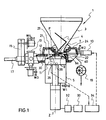
- a device according to the invention is shown schematically in section and designated 1 overall.
- the device has a filling funnel 3 open at the top, which opens downwards into an outlet, from which an opening 7 opens into the interior of a filling cylinder 5.
- a feeder curve 4 is arranged in the filling funnel 1, which, when it is set in rotary motion, conveys the mass filled into the filling funnel and to be transferred into the filling cylinder toward the opening 7.
- an inlet slide 9 is arranged, which is designed as a flat slide and, depending on the position, can more or less close or open the opening 7.
- the inlet valve 9 is controlled by a piston drive 10 which can be acted upon in two directions. The design of the inlet valve together with the opening will be described in more detail below.
- the filling cylinder 5, in which a piston 11 is guided, is arranged below the filling funnel 3. Laterally from the upper part of the filling cylinder 5, an outlet opening 12 leads to an outlet slide 13, which is shown as a rotary slide valve.
- the rotary slide valve connects the filling cylinder to a filling tube 17 on which a calibration gear 15 acts.
- a filling tube for cans or an attachment machine for portioning can also be connected.
- the filling cylinder 5 is closed at the top by the cover 30.
- the opening 7 which is laterally offset from the main axis of the cylinder.
- the opening 29 which laterally offset to the axis of the cylinder Z, which opens into a cavity 21 defined by a cover 24.
- This Space is connected to a space 22 to which a vacuum pump 19 can be connected.
- the opening 29, which leads from the space 21 into the filling cylinder, can be closed by a valve 26 designed in the manner of a pivoting flap.
- the valve 26 also serves as a sensor for detecting the fill level in the piston 5.
- the swivel flap 26 is designed so that it floats on the filled mass.
- signals can be derived from the position of the swivel flap, which reflect the fill level in the filling cylinder and thus in the region of the swivel flap the free space between the mass and cover 30.
- control device 34 emits signals for actuating the piston drive 10 for the inlet slide 9 and controls the inlet slide in such a way that an approximately constant large free space is output during the entire filling process of the filling cylinder 5 with mass the hopper 3 is maintained.
- the space 21 and the space 22 formed on the connection side of the vacuum pump 19 serve as a vacuum pressure compensation space and for water separation.
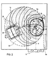
- FIG. 2 represents a top view of the cover 30.
- the opening 7 is arranged laterally offset to the main axis Z of the cylinder in the edge region approximately adjacent to the cylinder wall 5a.
- the opening 7 is designed as an elongated oval.
- the contour of the opening is provided with the reference number 7a.
- the inlet slide 9 is guided in a guide plate 9c.
- the direction of displacement V of the inlet slide 9 lies along a secant through the cylinder, which is aligned parallel to the longitudinal axis L of the elongated opening 7.
- the opening 7 is delimited by the front edge 9a of the inlet slide.
- the hatched area shows the opening cross section.
- the front edge 9a of the inlet slide 9 is provided with a rounded portion 9b towards the cylinder wall 5a.
- This special configuration of the opening and the leading edge of the inlet slide valve means that the inflowing mass in the slide valve position shown flows into the cylinder from above with a component inclined towards the cylinder wall 5a, which is indicated by the arrow E R.
- the inflowing mass therefore initially abuts the cylinder wall 5a over the region A, which is shown with a stronger line.
- the further temporal distribution of the mass is shown by the time lines T1, T2 to T n .
- the mass then spreads out according to this illustration in such a way that its fronts run along these lines at successive time intervals. It can be seen that the direction of propagation of these fronts can be represented approximately by the arrow P A.
- the swivel flap 26 which connects the cylinder interior in the open position with the vacuum and on the other hand takes over the task of the sensor which detects the fill level.
- this swivel flap lies in an area which the inflowing mass flow reaches last. In this area it is therefore possible to scan the swivel position of the flap for this to ensure that the inlet slide valve is regulated in such a way that this area is never completely filled, ie that a constant free space 36 is maintained in this area.
- the level in this area is therefore kept at an approximately constant level, so that the free space also remains constant.
- the device according to the invention works as follows to carry out the method according to the invention:
- the funnel 3 is filled with the air-containing mass to be portioned or filled either by hand or with a lifting device.
- the inlet slide 9 is closed.
- the valve or the swivel flap 26 is closed.
- the piston 11 has moved all the way up, i.e. the free volume between the cover and the piston surface is zero.
- the position of the piston or the control of the piston stroke is monitored by the position measuring system W1 (see FIG. 1).
- the swing flap 26 acting as a check valve falls off and connects the vacuum system to the cylinder interior.
- the rooms 21 and 22 and also the cylinder interior are evacuated.
- the outlet slide 13 is also closed.
- the back of the piston is also evacuated in a manner not shown.
- the inlet slide 9 is now opened. Due to the vacuum generated inside the cylinder, the mass filled in the hopper 3 is by the Opening 7 is sucked into the filling cylinder and is initially deflected towards the cylinder wall in accordance with the path forced on it. From there, the mass spreads in a wide fan flow, as shown in FIG. 2, in the direction of the swivel flap. The mass is deaerated during this entire process. The escaping air is drawn off via the wide, low channel 40, which leads from the area of the inlet slide to the cavity 21, and also via the opening 29, which is opened by the pivoting flap 26. The free space is then regulated to a constant value by detecting the position of the swivel flap, which also serves as a sensor, and by correspondingly controlling the inlet slide 9.
- the piston now moves further, with the growing interior filling up with the mass except for the free space 36, which remains the same size.
- the mass always takes the path imposed on it and is vented evenly and with high efficiency.
- the time from the first opening of the inlet slide 9 to the first floating of the swivel flap 26 in the starting phase passes, measured.
- control conditions are then selected and stored, for example, in a microprocessor, not shown, which then controls the functions for the further filling cycles.
- the piston is then moved upwards for the ejection movement. It displaces the remaining air above the mass. Since the swivel flap is arranged such that when swiveling up, the swivel flap is only completely closed when the free space 36 has become zero, the swivel flap 26 only closes when the air has actually completely escaped from the free space or there is no more free space is.
- the pressure prevailing in the cylinder 5 must remain almost constant over the entire filling period. This is achieved by building up pressure before the actual start of ejection. This can be done by waiting for the outlet slide to open until a preset pressure value has built up.
- the value of the required filling pressure can also be determined again after each start of work (batch change or tempo change) by a measuring process in the start phase.
- the pressure sensor 32 detects the pressure which is thereby established in the cylinder space.
- This pressure increases gradually and then increases to a constant pressure value, which is stored in a control unit 33.
- this stored pressure value is then used as a specification for the pressure build-up, i.e. the outlet slide 13 remains closed for the further cylinder fillings until the pressure reaches the stored value.
- the outlet slide 13 opens and the mass is ejected under constant pressure with a constant filling flow, i.e. at a preset speed.
- the portioning is carried out by gradually moving the piston 11, the portioning stroke for the ejection speed is detected by the displacement measuring system W1 and regulated by a servo valve via a digital electronic control (not shown).
- the rotary valve 13 is opened at the beginning of a portion ejection and closed again after the end thereof.
- the pulse generator W4 detects the actual value of the speed, which is compared in a control device with the setpoint.
- the entire cylinder volume can also be filled.
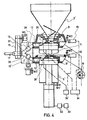
- the device comprises two cylinders 5 and 5 ', each of which is connected to a separate outlet opening formed on the filling funnel 3'.
- a slide 9 and 9 ' is provided in each outlet opening, the specific embodiment being carried out in accordance with the exemplary embodiment described with reference to FIGS. 2 and 3.
- the slides 9 and 9 ' are each regulated with associated swivel flaps 26 and 26'.
- the cylinders 5 and 5 ' are only indicated in principle in the drawing and are arranged in a specific embodiment, for example side by side at a parallel height under the assigned inlet slide 9 or 9'. The mode of operation corresponds essentially to that described above.
- the outlet openings 12 and 12 'of the two cylinders 5 and 5' are brought together to form a common filling pipe 17 through channels 37 and 39 converging in a unit 38.
- the inlet slides are controlled via associated control devices 34 and 34 ', as already described above.
- the respective position of the inlet slide is detected by sensors W2 and W2 'and used in the control circuit.
- a calibration gear 15 shown does not necessarily have to be present on the filling tube 17, but rather this device can also be used for continuous filling, portioning or for loading front-mounted machines, in all cases the filling material having a very low residual air content, as before described, can be vented.
Landscapes
- Life Sciences & Earth Sciences (AREA)
- Engineering & Computer Science (AREA)
- Wood Science & Technology (AREA)
- Zoology (AREA)
- Food Science & Technology (AREA)
- Basic Packing Technique (AREA)
- Processing Of Meat And Fish (AREA)
Claims (20)
- Procédé pour bourrer des produits déformables et contenant de l'air, en particulier pour bourrer des chairs à saucisses, par lequel le produit est transféré en un flux massique d'un entonnoir de remplissage (3) à un cylindre de remplissage (5) dans lequel est créée, pour l'aération du produit, une dépression par rapport à l'entonnoir de remplissage (3) et par lequel la masse transférée est expulsée du cylindre de remplissage (5) au moyen d'un piston (11) monté dans celui-ci, caractérisé en ce que, lors du transfert dans le cylindre de remplissage (5), le flux massique est dirigé de telle façon que, à l'entrée dans le cylindre de remplissage (5), il se déplace tout d'abord en direction de la paroi (5a) du cylindre en formant un angle avec la direction de déplacement du piston (11), et que pendant l'introduction du produit dans le cylindre de remplissage (5), le niveau de remplissage est réglé de façon à conserver pendant le remplissage un espace libre sensiblement constant dans le cylindre de remplissage.
- Procédé selon la revendication 1, caractérisé en ce que, à partir du commencement de l'opération de remplissage, l'espace intérieur chargeable du cylindre de remplissage (5) est agrandi en continu à partir de zéro par la descente du piston (11).
- Procédé selon la revendication 2, caractérisé en ce que, pendant le remplissage, l'espace libre est maintenu constant par le réglage de la section de passage d'une ouverture (7) par laquelle le flux massique passe de l'entonnoir de remplissage (3) dans le cylindre de remplissage (5) disposé en dessous de celui-ci.
- Procédé selon l'une des revendications 1 à 3, caractérisé en ce que l'aération du cylindre de remplissage (5) est effectuée à un endroit diamétralement opposé au point d'impact du flux massique sur la paroi (5a) du cylindre et situé au point le plus haut du cylindre de remplissage.
- Procédé selon l'une des revendications précédentes, caractérisé en ce que l'entonnoir de remplissage (3) est maintenu sous pression atmosphérique pendant le chargement du cylindre de remplissage (5).
- Dispositif pour bourrer des produits déformables et contenant de l'air, en particulier pour bourrer des chairs à saucisses, comprenant un entonnoir de remplissage (3), un cylindre de remplissage (5) communiquant avec l'entonnoir de remplissage (3) par l'intermédiaire d'une ouverture (7) obturable au moyen d'un tiroir d'entrée (9) et équipé d'un piston (11) une ouverture de sortie (12) commandée par tiroir par laquelle la masse transportée de l'entonnoir de remplissage (3) dans le cylindre de remplissage (5) peut être expulsée en quantités dosées par la commande de la course du piston, et une soupape (26) par l'intermédiaire de laquelle le cylindre de remplissage (5) est mis sous vide lors de l'introduction de la masse à partir de l'entonnoir de remplissage (3), caractérisé en ce que l'ouverture (7) est disposée et conformée de telle façon que le flux massique, en passant, est dirigé sur la paroi (5a) du cylindre, qu'il est prévu un détecteur (26, 26') qui détecte le niveau de remplissage pendant le chargement du cylindre de remplissage (5, 5'), et qu'il est prévu un dispositif de réglage qui, lors du mouvement descendant du piston intervenant lors du remplissage, commande le tiroir d'entrée (9, 9') en fonction des signaux du détecteur (26, 26') de façon à conserver lors du remplissage un espace libre (36) sensiblement constant entre la masse et le couvercle (30) du cylindre de remplissage.
- Dispositif selon la revendication 6, caractérisé en ce que l'ouverture (7) dans le couvercle du cylindre de remplissage est décalée latéralement par rapport à l'axe (Z) du cylindre de remplissage (5) , et que la soupape (26) est disposée dans le couvercle (30) du cylindre, dans une position sensiblement diamétralement opposée à l'endroit (région A) où le flux massique entrant par l'ouverture arrive sur la paroi (5a) du cylindre.
- Dispositif selon l'une des revendications 6 ou 7, caractérisé en ce que la déviation du flux massique vers la paroi (5a) du cylindre est réalisée par une conformation correspondante (9b) du bord antérieur (9b) du tiroir d'entrée (9) qui délimite l'ouverture (7).
- Dispositif selon l'une des revendications 6 à 8, caractérisé en ce que la soupape (26) est conformée en clapet pivotant et constitue en même temps le détecteur.
- Dispositif selon l'une des revendications 6 à 9, caractérisé en ce que le dispositif de réglage (34) agit sur la section de passage de l'ouverture (7) par le réglage du tiroir d'entrée (9) pour maintenir l'espace libre constant.
- Dispositif selon l'une des revendications 6 à 10, caractérisé en ce qu au-dessus du couvercle (30) du cylindre de remplissage est prévu un chapeau (24) qui délimite une cavité (21, 22) à laquelle est raccordé le système à vide (19) et avec laquelle le cylindre de remplissage (5) communique par l'intermédiaire de la soupape (26, 26').
- Dispositif selon l'une des revendications précédentes, caractérisé en ce que dans la région du tiroir d'entrée (9) débouche, du côté du cylindre de remplissage, un canal (40) large mais court qui conduit à la cavité (21, 22).
- Dispositif selon l'une des revendications précédentes, caractérisé en ce que l'entonnoir de remplissage (3) est ouvert en haut.
- Dispositif selon la revendication 9, caractérisé en ce qu'il comprend un chronomètre qui mesure le temps écoulé entre l'ouverture du tiroir d'entrée (9) et le premier flottement du clapet pivotant (26), et que les conditions de réglage du circuit de réglage (26, 26'; 10, 10') sont définies pour une masse déterminée en fonction de ce temps.
- Dispositif selon l'une des revendications précédentes, caractérisé en ce qu'il comprend une unité de commande (33) qui détermine, après chaque début d'un cycle de remplissage déterminé, la pression d'expulsion nécessaire dans la phase de démarrage de l'opération d'expulsion.
- Dispositif selon la revendication 15, caractérisé en ce que l'unité de commande (33) est reliée à un détecteur manométrique (32) et détermine respectivement pour un premier remplissage du cylindre la courbe de pression à l'expulsion, et qu'une valeur de pression stabilisée de l'unité de commande (33) alors déterminée est mémorisée et utilisée respectivement pour le cycle suivant comme valeur de consigne pour la montée en pression.
- Dispositif selon la revendication 15, caractérisé en ce que l'unité de commande (33) est reliée à un détecteur manométrique (32) et détermine respectivement pour un premier remplissage du cylindre la courbe de pression à l'expulsion, et qu'une valeur de pression stabilisée de l'unité de commande (33) alors déterminée est mémorisée et utilisée pour les cycles de remplissage suivants comme valeur de consigne pour la montée en pression.
- Dispositif selon l'une des revendications précédentes, caractérisé en ce que l'entonnoir de remplissage (3) comporte deux sorties qui permettent le chargement de respectivement un cylindre de remplissage associé (5, 5') par l'intermédiaire de respectivement un tiroir d'entrée (9, 9') réglé.
- Dispositif selon la revendication 18, caractérisé en ce que les tiroirs d'entrée (9, 9') peuvent être réglés indépendamment l'un de l'autre.
- Dispositif selon l'une des revendications 18 ou 19, caractérisé en ce que le mouvement d'expulsion de l'un des cylindres (5, 5') est coordonné avec la montée de l'autre cylindre (5', 5) de façon à conserver un flux volumique constant.
Priority Applications (2)
| Application Number | Priority Date | Filing Date | Title |
|---|---|---|---|
| IN912/MAS/86A IN168649B (fr) | 1985-12-16 | 1986-11-27 | |
| AT86116944T ATE61910T1 (de) | 1985-12-16 | 1986-12-05 | Verfahren und vorrichtung zum abfuellen lufthaltiger, verformbarer massen. |
Applications Claiming Priority (2)
| Application Number | Priority Date | Filing Date | Title |
|---|---|---|---|
| DE19853544448 DE3544448A1 (de) | 1985-12-16 | 1985-12-16 | Verfahren und vorrichtung zum abfuellen lufthaltiger, verformbarer massen |
| DE3544448 | 1985-12-16 |
Publications (2)
| Publication Number | Publication Date |
|---|---|
| EP0229296A1 EP0229296A1 (fr) | 1987-07-22 |
| EP0229296B1 true EP0229296B1 (fr) | 1991-03-27 |
Family
ID=6288564
Family Applications (1)
| Application Number | Title | Priority Date | Filing Date |
|---|---|---|---|
| EP86116944A Expired - Lifetime EP0229296B1 (fr) | 1985-12-16 | 1986-12-05 | Procédé et dispositif pour bourrer des produits déformables et contenant de l'air |
Country Status (12)
| Country | Link |
|---|---|
| US (1) | US4723581A (fr) |
| EP (1) | EP0229296B1 (fr) |
| JP (1) | JPS62146551A (fr) |
| CN (1) | CN1007053B (fr) |
| AU (1) | AU587509B2 (fr) |
| BR (1) | BR8606202A (fr) |
| CA (1) | CA1304979C (fr) |
| CS (1) | CS8609250A3 (fr) |
| DE (2) | DE3544448A1 (fr) |
| ES (1) | ES2020928B3 (fr) |
| PL (1) | PL151908B1 (fr) |
| SU (1) | SU1590030A3 (fr) |
Families Citing this family (23)
| Publication number | Priority date | Publication date | Assignee | Title |
|---|---|---|---|---|
| DE3617560C2 (de) * | 1986-05-24 | 1996-08-14 | Schnell Maschfab Karl | Maschine zum Abfüllen teigiger Medien, insbesondere von Wurstbrät |
| DE3837097A1 (de) * | 1988-11-01 | 1990-05-03 | Profor Ab | Verfahren zum entlueften einer befuellungsanlage und vorrichtung zur durchfuehrung eines solchen verfahrens |
| ES2015660A6 (es) * | 1989-05-19 | 1990-09-01 | Metalquimia Sa | Procedimiento para dosificacion y embutido de masas carnicas, al vacio y maquina para su realizacion. |
| US5265956A (en) * | 1991-09-30 | 1993-11-30 | Stryker Corporation | Bone cement mixing and loading apparatus |
| US5252037A (en) * | 1992-07-30 | 1993-10-12 | Aseptic Technology Engineering Co. | Piston valved vertical pump for particulate materials |
| US5378193A (en) * | 1993-07-07 | 1995-01-03 | Teepak, Inc. | Vacuum stuffing horn and method for using same |
| US5558136A (en) * | 1994-01-31 | 1996-09-24 | Stryker Corporation | Bone cement cartridge with secondary piston |
| US5797679A (en) * | 1996-02-09 | 1998-08-25 | Stryker Corporation | Surgical cement mixer apparatus |
| ES2134689B1 (es) * | 1996-02-21 | 2000-04-16 | Ind Fuerpla S L C I F | Perfeccionamientos introducidos en las maquinas embutidoras de productos carnicos con dosificacion continua. |
| ATE334595T1 (de) * | 2002-04-17 | 2006-08-15 | Metalquimia Sa | Füll/dosier-maschine mit einem kipptrichter |
| DE102007030359A1 (de) * | 2007-06-29 | 2009-01-02 | Wolfgang Karl Dipl.-Ing. Müller | Verfahren zum Dosieren eines nichtflüssigen Materials und Dosiervorrichtung |
| ES2537111T3 (es) * | 2010-12-22 | 2015-06-02 | Albert Handtmann Maschinenfabrik Gmbh & Co. Kg | Dispositivo y procedimiento para la distribución del aire residual en masas pastosas, en particular para la elaboración de embutidos |
| NL2006958C2 (en) * | 2011-06-17 | 2012-12-18 | Marel Townsend Further Proc Bv | Processing a mass of pumpable foodstuff material. |
| DE102011051604A1 (de) * | 2011-07-06 | 2013-01-10 | Maschinenfabrik Leonhardt Gmbh | Abscheide- und Rückführungssystem von Lebensmitteln |
| EP2781160B1 (fr) * | 2013-03-21 | 2016-11-30 | Albert Handtmann Maschinenfabrik GmbH & Co. KG | Dispositif de fabrication de produits alimentaires coextrudés |
| CN103609652A (zh) * | 2013-12-24 | 2014-03-05 | 南京年吉冷冻食品有限公司 | 一种真空搅拌灌肠机 |
| CN104627402B (zh) * | 2015-01-30 | 2018-03-30 | 石家庄博安不锈钢设备有限公司 | 一种活塞连续真空灌装结构 |
| CN108216710A (zh) * | 2018-02-26 | 2018-06-29 | 福州法莫优科机械科技有限公司 | 立式气动灌装装置及其使用方法 |
| CN110637863A (zh) * | 2019-08-30 | 2020-01-03 | 徐州爱迪食品有限公司 | 一种用于工厂物料打包的灌装设备 |
| CN112660446B (zh) * | 2020-12-15 | 2023-04-28 | 广东宏川环宇智能装备有限公司 | 高速液体包装机的立式泵阀灌装机构 |
| CN112868732B (zh) * | 2021-03-23 | 2022-04-19 | 邵阳米农有机农业发展有限公司 | 一种防止空料的香肠加工装置 |
| CN112977911B (zh) * | 2021-04-27 | 2022-12-27 | 广东雅筑生物科技有限公司 | 一种双头全自动活塞式膏体灌装机 |
| CN115196065B (zh) * | 2022-07-26 | 2024-05-17 | 胡振先 | 一种高纯化学品装灌设备 |
Family Cites Families (13)
| Publication number | Priority date | Publication date | Assignee | Title |
|---|---|---|---|---|
| US3161910A (en) * | 1962-11-02 | 1964-12-22 | Alvin W Hughes | Sausage stuffing machine |
| US3166786A (en) * | 1963-02-21 | 1965-01-26 | John E Thompson | Sausage stuffeer |
| US3189940A (en) * | 1963-09-18 | 1965-06-22 | Alvin W Hughes | Deaerating machine for sausage batter or the like |
| FR1400631A (fr) * | 1964-05-08 | 1965-05-28 | Hoegger & Cie Ag C | Machine de remplissage pour saucisses, à fonctionnement continu |
| US3537129A (en) * | 1967-07-13 | 1970-11-03 | Mayer & Co Inc O | Continuous stuffing system |
| DE2038010A1 (en) * | 1969-11-29 | 1971-06-09 | Jara Javaloy, Jose Manuel, Prenafeta Garrusta Jaime, Barcelona (Spanien) | Sausage meat filler |
| US4317259A (en) * | 1979-10-22 | 1982-03-02 | Hollymatic Corporation | Molding apparatus |
| DE3018793A1 (de) * | 1980-05-16 | 1981-11-26 | Albert Handtmann Gmbh & Co, 7950 Biberach | Anordnung zum aufeinanderfolgenden portionieren einer fliessfaehigen fuellmasse, insbesondere wurstmasse |
| US4457348A (en) * | 1982-07-07 | 1984-07-03 | Mueller Martin J | Food product fill pump |
| DE3227616A1 (de) * | 1982-07-23 | 1984-01-26 | Heinrich 7922 Herbrechtingen Frey | Verfahren und anordnung zum abfuellen eines verformbaren und fliessfaehigen fuellgutvorrats |
| DE3232185A1 (de) * | 1982-08-30 | 1984-03-29 | Modell- und Maschinenfabrik Meissner & Co, 3560 Biedenkopf | Portionier-verfahren und vorrichtung |
| DE3319139A1 (de) * | 1983-05-26 | 1984-11-29 | Frey, Heinrich, 7922 Herbrechtingen | Vorrichtung zum abfuellen eines verformbaren und fliessfaehigen fuellgutes |
| US4562615A (en) * | 1984-04-26 | 1986-01-07 | Oscar Mayer Foods Corporation | Apparatus and method for dispensing uniform quantities of ham products |
-
1985
- 1985-12-16 DE DE19853544448 patent/DE3544448A1/de not_active Withdrawn
-
1986
- 1986-11-27 AU AU65778/86A patent/AU587509B2/en not_active Ceased
- 1986-12-05 ES ES86116944T patent/ES2020928B3/es not_active Expired - Lifetime
- 1986-12-05 EP EP86116944A patent/EP0229296B1/fr not_active Expired - Lifetime
- 1986-12-05 DE DE8686116944T patent/DE3678416D1/de not_active Expired - Fee Related
- 1986-12-10 SU SU864028635A patent/SU1590030A3/ru active
- 1986-12-10 CN CN86108212A patent/CN1007053B/zh not_active Expired
- 1986-12-12 CS CS869250A patent/CS8609250A3/cs unknown
- 1986-12-12 PL PL1986262954A patent/PL151908B1/pl unknown
- 1986-12-15 US US06/941,816 patent/US4723581A/en not_active Expired - Fee Related
- 1986-12-15 BR BR8606202A patent/BR8606202A/pt not_active IP Right Cessation
- 1986-12-16 CA CA000525436A patent/CA1304979C/fr not_active Expired - Lifetime
- 1986-12-16 JP JP61299789A patent/JPS62146551A/ja active Granted
Also Published As
| Publication number | Publication date |
|---|---|
| CN1007053B (zh) | 1990-03-07 |
| US4723581A (en) | 1988-02-09 |
| SU1590030A3 (ru) | 1990-08-30 |
| AU587509B2 (en) | 1989-08-17 |
| PL262954A1 (en) | 1988-02-18 |
| CA1304979C (fr) | 1992-07-14 |
| AU6577886A (en) | 1987-06-18 |
| CS275113B2 (en) | 1992-02-19 |
| DE3678416D1 (de) | 1991-05-02 |
| JPS62146551A (ja) | 1987-06-30 |
| ES2020928B3 (es) | 1991-10-16 |
| CS8609250A3 (en) | 1992-02-19 |
| JPH0561893B2 (fr) | 1993-09-07 |
| DE3544448A1 (de) | 1987-06-19 |
| EP0229296A1 (fr) | 1987-07-22 |
| PL151908B1 (en) | 1990-10-31 |
| CN86108212A (zh) | 1987-07-15 |
| BR8606202A (pt) | 1987-09-29 |
Similar Documents
| Publication | Publication Date | Title |
|---|---|---|
| EP0229296B1 (fr) | Procédé et dispositif pour bourrer des produits déformables et contenant de l'air | |
| EP2785594B1 (fr) | Machine d'emballage et procédé de remplissage de sacs | |
| EP1056589B1 (fr) | Procede permettant de faire fonctionner une presse a paquets par cisaillement et presse a paquets par cisaillement | |
| DE2612938C2 (de) | Verfahren und Vorrichtung zum Herstellen von Käseblöcken | |
| DE10015952A1 (de) | Gärbehälter, insbesondere für die Rotweinherstellung | |
| DE4013290C1 (fr) | ||
| DE2912471C2 (fr) | ||
| DE1573126A1 (de) | Vorrichtung zum Abmessen und Vermischen von trockenen,gekoernten Materialien | |
| DE3503696A1 (de) | Steuersystem fuer zentrifugen | |
| DE2260768A1 (de) | Kontinuierlicher mischer mit einer rueckgekoppelten steuereinrichtung | |
| CH641529A5 (de) | Vorrichtung zur foerderung und dosierung abgemessener materialmengen, insbesondere von giessharzkomponenten. | |
| EP0366997B1 (fr) | Procédé pour désaérer une installation de remplissage et dispositif pour la mise en oeuvre du procédé | |
| CH666223A5 (de) | Verfahren und vorrichtung zum befuellen eines hin- und herbeweglichen fuellschiebers einer formpresse mit pressmasse. | |
| DD252755A5 (de) | Verfahren und Vorrichtung zum Abfüllen lufthaltiger, verformbarer Massen | |
| DE1757640B1 (de) | Vorrichtung zum fortlaufenden Bewegen eines zusammenhaftenden zerkleinerten Materials,beispielsweise Tabaks | |
| DE1800766C2 (de) | Verfahren zum Entwässern von Käsebruch und zum Formen von Käse | |
| DE2017888A1 (de) | Verfahren und Vorrichtung zum Beschicken von Schmelzelektrolysewannen für die Aluminiumherstellung mit Tonerde | |
| DE2416151B1 (fr) | ||
| AT405007B (de) | Flügelzellenpumpe zum portionieren einer pastösen und kompressiblen masse sowie verfahren zu deren betrieb | |
| DE3223803C2 (de) | Verfahren und Einrichtung zur Regelung des Füllvorganges aneinandergereihter Gießformen | |
| DE10140411B4 (de) | Verfahren und Vorrichtung zum Befüllen von Koksofenkammern einer Koksofenbatterie | |
| DE3942809C2 (fr) | ||
| DE2819705C2 (de) | Tabakaufnahmeeinheit für den Verteiler einer Zigarettenherstellungsmaschine | |
| DE3528571C2 (fr) | ||
| EP0129703A1 (fr) | Procédé et dispositif pour bourrer des produits déformables et coulants |
Legal Events
| Date | Code | Title | Description |
|---|---|---|---|
| PUAI | Public reference made under article 153(3) epc to a published international application that has entered the european phase |
Free format text: ORIGINAL CODE: 0009012 |
|
| AK | Designated contracting states |
Kind code of ref document: A1 Designated state(s): AT CH DE ES FR GB IT LI NL |
|
| ITCL | It: translation for ep claims filed |
Representative=s name: SOCIETA' ITALIANA BREVETTI S.P.A. |
|
| 17P | Request for examination filed |
Effective date: 19870818 |
|
| EL | Fr: translation of claims filed | ||
| 17Q | First examination report despatched |
Effective date: 19890428 |
|
| GRAA | (expected) grant |
Free format text: ORIGINAL CODE: 0009210 |
|
| ITF | It: translation for a ep patent filed |
Owner name: SOCIETA' ITALIANA BREVETTI S.P.A. |
|
| AK | Designated contracting states |
Kind code of ref document: B1 Designated state(s): AT CH DE ES FR GB IT LI NL |
|
| PG25 | Lapsed in a contracting state [announced via postgrant information from national office to epo] |
Ref country code: NL Effective date: 19910327 |
|
| REF | Corresponds to: |
Ref document number: 61910 Country of ref document: AT Date of ref document: 19910415 Kind code of ref document: T |
|
| ET | Fr: translation filed | ||
| GBT | Gb: translation of ep patent filed (gb section 77(6)(a)/1977) | ||
| REF | Corresponds to: |
Ref document number: 3678416 Country of ref document: DE Date of ref document: 19910502 |
|
| NLV1 | Nl: lapsed or annulled due to failure to fulfill the requirements of art. 29p and 29m of the patents act | ||
| PLBE | No opposition filed within time limit |
Free format text: ORIGINAL CODE: 0009261 |
|
| STAA | Information on the status of an ep patent application or granted ep patent |
Free format text: STATUS: NO OPPOSITION FILED WITHIN TIME LIMIT |
|
| 26N | No opposition filed | ||
| PGFP | Annual fee paid to national office [announced via postgrant information from national office to epo] |
Ref country code: GB Payment date: 19921124 Year of fee payment: 7 |
|
| PGFP | Annual fee paid to national office [announced via postgrant information from national office to epo] |
Ref country code: FR Payment date: 19921208 Year of fee payment: 7 |
|
| PG25 | Lapsed in a contracting state [announced via postgrant information from national office to epo] |
Ref country code: GB Effective date: 19931205 |
|
| GBPC | Gb: european patent ceased through non-payment of renewal fee |
Effective date: 19931205 |
|
| PG25 | Lapsed in a contracting state [announced via postgrant information from national office to epo] |
Ref country code: FR Effective date: 19940831 |
|
| REG | Reference to a national code |
Ref country code: FR Ref legal event code: ST |
|
| PGFP | Annual fee paid to national office [announced via postgrant information from national office to epo] |
Ref country code: AT Payment date: 19961122 Year of fee payment: 11 |
|
| PGFP | Annual fee paid to national office [announced via postgrant information from national office to epo] |
Ref country code: ES Payment date: 19961209 Year of fee payment: 11 |
|
| PGFP | Annual fee paid to national office [announced via postgrant information from national office to epo] |
Ref country code: CH Payment date: 19970130 Year of fee payment: 11 |
|
| PG25 | Lapsed in a contracting state [announced via postgrant information from national office to epo] |
Ref country code: AT Free format text: LAPSE BECAUSE OF NON-PAYMENT OF DUE FEES Effective date: 19971205 |
|
| PG25 | Lapsed in a contracting state [announced via postgrant information from national office to epo] |
Ref country code: LI Free format text: LAPSE BECAUSE OF NON-PAYMENT OF DUE FEES Effective date: 19971231 Ref country code: CH Free format text: LAPSE BECAUSE OF NON-PAYMENT OF DUE FEES Effective date: 19971231 |
|
| REG | Reference to a national code |
Ref country code: CH Ref legal event code: PL |
|
| PG25 | Lapsed in a contracting state [announced via postgrant information from national office to epo] |
Ref country code: ES Free format text: LAPSE BECAUSE OF NON-PAYMENT OF DUE FEES Effective date: 19981206 |
|
| PGFP | Annual fee paid to national office [announced via postgrant information from national office to epo] |
Ref country code: DE Payment date: 20020128 Year of fee payment: 16 |
|
| PG25 | Lapsed in a contracting state [announced via postgrant information from national office to epo] |
Ref country code: DE Free format text: LAPSE BECAUSE OF NON-PAYMENT OF DUE FEES Effective date: 20030701 |
|
| REG | Reference to a national code |
Ref country code: ES Ref legal event code: FD2A Effective date: 19990114 |
|
| PG25 | Lapsed in a contracting state [announced via postgrant information from national office to epo] |
Ref country code: IT Free format text: LAPSE BECAUSE OF NON-PAYMENT OF DUE FEES;WARNING: LAPSES OF ITALIAN PATENTS WITH EFFECTIVE DATE BEFORE 2007 MAY HAVE OCCURRED AT ANY TIME BEFORE 2007. THE CORRECT EFFECTIVE DATE MAY BE DIFFERENT FROM THE ONE RECORDED. Effective date: 20051205 |